Table of Contents
Advertisement
Quick Links
Statement:
This manual is the intellectual property of Foxconn Inc. Although the
information in this manual may be changed or modified at any time,
Foxconn does not obligate itself to inform the user of these changes.
Trademark:
All trademarks are the property of their respective owners.
Version:
User's Manual V1.1 in English for NF3250K8AA/NF3250GK8AA series
motherboard.
P/N: 91-181-NF3-AA-1E
Symbol description:
Note: refers to important information that can help you to use motherboard
better.
Attention: indicates that it may damage hardware or cause data loss,
and tells you how to avoid such problems.
Warning: means that a potential risk of property damage or physical
injury exists.
More information:
If you want more information about our products, please visit the following
website: http://www.foxconnchannel.com
Advertisement
Table of Contents

Related Manuals for Foxconn NF3250K8AA


Summary of Contents for Foxconn NF3250K8AA
- Page 1 This manual is the intellectual property of Foxconn Inc. Although the information in this manual may be changed or modified at any time, Foxconn does not obligate itself to inform the user of these changes. Trademark: All trademarks are the property of their respective owners.
- Page 2 HON HAI PRECISION INDUSTRY COMPANY LTD 66 , CHUNG SHAN RD., TU-CHENG INDUSTRIAL DISTRICT, TAIPEI HSIEN, TAIWAN, R.O.C. declares that the product Motherboard NF3250K8AA/NF3250GK8AA is in conformity with (reference to the specification under which conformity is declared in accordance with 89/336 EEC-EMC Directive) þ...
- Page 3 Declaration of conformity Trade Name: WinFast Model Name: NF3250K8AA/NF3250GK8AA Responsible Party: PCE Industry Inc. Address: 458 E. Lambert Rd. Fullerton, CA 92835 Telephone: 714-738-8868 Facsimile: 714-738-8838 Equipment Classification: FCC Class B Subassembly Type of Product: Motherboard Manufacturer: HON HAI PRECISION INDUSTRY...
-
Page 4: Table Of Contents
Table of Contents Chapter Product Introduction Main Features ..................... 2 Motherboard Layout ................... 4 Chapter Installation Instructions CPU ......................7 Memory ....................11 Power Supply ................... 12 Rear Panel Connectors ................13 Other Connectors ..................15 Expansion Slots ..................19 Jumpers .................... - Page 5 Table of Contents Chapter Driver CD Introduction Utility CD content ..................46 Start to install drivers ................47 Chapter NVIDIA RAID Introduction RAID Arrays ..................... 49 Basic Configuration Instructions ............... 50 Setting Up the BIOS .................. 51 Entering the RAID BIOS Setup ..............52 NVIDIA RAID Utility Installation ..............
- Page 6 Warning: 1. Attach the CPU and heatsink using silica gel to ensure full contact. 2. It is suggested to select high-quality, certified fans in order to avoid damage to the motherboard and CPU due to high temperature. 3. Never turn on the machine if the CPU fan is not properly installed. 4.
- Page 7 This manual is suitable for motherboard of NF3250K8AA/ NF3250GK8AA series. Each motherboard is carefully designed for the PC user who wants diverse features. with onboard 100M LAN with onboard 1G LAN with 6-channel audio with 8-channel audio with 1394 with SATA with RAID You can find PPID label on the motherboard.
- Page 8 Chapter Thank you for buying WinFast NF3250K8AA/NF3250GK8AA series motherboard. This series of motherboard is one of our new products, and offers superior performance, reliabil- ity and quality, at a reasonable price. This motherboard adopts the advanced NVIDIA nForce3 250/nForce3 250Gb chipset, providing users a computer platform with a high integration-compatibility-performance price ratio.
-
Page 9: Chapter 1 Product Introduction
NVIDIA RAID Technology Supports RAID 0, RAID 1, RAID 0+1 and JBOD Cross-controller RAID uniquely supports both SATA and PATA disk devices within a single array Silicon 3112A RAID Technology (optional) Supports RAID 0, RAID 1 NF3250K8AA/NF3250GK8AA Series User Manual... - Page 10 Expansion Slots Five PCI slots One AGP slot AGP 8X support Supports AGP 8X graphics cards Advanced Features PCI 2.3 Specification Compliant Supports PC Health function (capable of monitoring system voltage, CPU/ system temperature, and fan speed) NF3250K8AA/NF3250GK8AA Series User Manual...
-
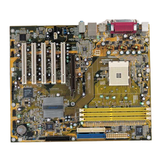
Page 11: Motherboard Layout
25. CD_IN Connector 12. BIOS TBL Jumper 26. AUX_IN Connector 13. Front Panel Connector 27. PCI Expansion slots 14. Floppy Disk Connector Note:The above motherboard layout is provided for reference only; please refer to the physical motherboard. NF3250K8AA/NF3250GK8AA Series User Manual... -
Page 12: Cpu
Please refer to the motherboard layout prior to any installation and read the contents in this chapter carefully. This chapter includes the following information: Memory Power Supply Rear Panel Connectors Other Connectors Expansion Slots Jumpers NF3250K8AA/NF3250GK8AA Series User Manual... - Page 13 3. Hold components by their edges to avoid touching any exposed integrated circuits (ICs). 4. W henever you uninstall a component, place it on a grounded anti- static pad or into the anti-static bag that it came in. NF3250K8AA/NF3250GK8AA Series User Manual...
- Page 14 3. W hen the CPU is in place, press it firmly on the socket while you push down the socket lever to secure the CPU. The lever clicks on the side tab to indicate that it is locked. NF3250K8AA/NF3250GK8AA Series User Manual...
- Page 15 (s u rro u n d s t h e C P U silica gel to the top of the CPU. socket) (If the rentention mechanism not be installed). NOTE: The CPU heatsink may have a pre-applied thermal compound. In that case, the silica gel is not required. NF3250K8AA/NF3250GK8AA Series User Manual...
- Page 16 5. Push down the retention bracket lock on the retention mechanism to secure the heatsink and fan to module base. NF3250K8AA/NF3250GK8AA Series User Manual...
- Page 17 Chapter 2 Installation Instructions 6. Connect the fan’s power cable to the appropriate 3-pin terminal on the motherboard. NF3250K8AA/NF3250GK8AA Series User Manual...
- Page 18 Note: Be sure to unplug the AC power supply before adding or re- moving expansion cards or other system peripherals, espe- cially the memory devices, otherwise your motherboard or the system memory might be seriously damaged. NF3250K8AA/NF3250GK8AA Series User Manual...
- Page 19 Attention: You have to press the power button for more than four seconds if you change the default Instant-off setting to “Delay 4 Sec” for the “Soft-Off by PBTN” option in the BIOS Power Management Setup. NF3250K8AA/NF3250GK8AA Series User Manual...
-
Page 20: Rear Panel Connectors
This 9-pin COM2 port is for pointing devices or other serial devices. 1394 Port (optional) This digital interface supports electronic devices such as digital cameras, scanners, and printers. USB 2.0 Ports These four Universal Serial Bus (USB) ports are available for connecting USB 2.0/1.1 devices. NF3250K8AA/NF3250GK8AA Series User Manual... - Page 21 W hen using a 6-channel sound source, connect the front speaker to the green audio output; connect the surround sound speaker to the blue audio output; connect the center speaker/subwoofer to the red Microphone output. Blue Green Center Front Left Front Right Rear Right Rear Left Subwoof er NF3250K8AA/NF3250GK8AA Series User Manual...
-
Page 22: Other Connectors
1 of the PIDE/SIDE or FLOPPY connector on the motherboard. Front Panel Connector: FP1 PLED PWRBTN# This motherboard includes one connector for con- necting the front panel switch and LED indicator. IDE_LED RESET FP1! NF3250K8AA/NF3250GK8AA Series User Manual... - Page 23 The 1394 expansion cable can be connected to ei- +12V +12V TPB- TPB+ ther the front (provided that the front panel of your chassis is equipped with the appropriate interface) TPA- TPA+ or the rear panel of the chassis. F_1394 NF3250K8AA/NF3250GK8AA Series User Manual...
- Page 24 If you do not want to use the Front F_AUDIO Audio, pin 5 and 6, pin 9 and 10 must be short, and then the signal will be sent to the rear au- dio port. NF3250K8AA/NF3250GK8AA Series User Manual...
- Page 25 “WOR(RI#) From Soft-Off” as “Enabled” in the “Power Manage- ment Setup” section of the CMOS Setup. Save and exit, then boot the operating system once to make sure this function takes effect. NF3250K8AA/NF3250GK8AA Series User Manual...
-
Page 26: Expansion Slots
AGP Qualified Vendor List The following table lists the AGP cards that have been tested and qualified for use with this motherboard. For more details graphics card support list qualified on this motherboard, plsease visit the website: http://www.foxconnchannel.com NF3250K8AA/NF3250GK8AA Series User Manual... -
Page 27: Jumpers
3. Turn on the system. The BIOS is returned to the default settings. Warning: 1. Disconnect the power cable before adjusting the jumper settings. 2. DO NOT clear the CMOS while the system is turned on. NF3250K8AA/NF3250GK8AA Series User Manual... - Page 28 Disable information to recover the BIOS even if flash BIOS fail. To utilize this function, you just leave this jumper TBL_EN as pin 2 and 3 together with the jumper cap. NF3250K8AA/NF3250GK8AA Series User Manual...
- Page 29 BIOS setting. Pressing the power switch for more than 4 seconds lets the system enter the soft-off mode regardless of the BIOS setting. NF3250K8AA/NF3250GK8AA Series User Manual...
-
Page 30: Enter Bios Setup
Chapter This chapter tells how to change system settings through the BIOS Setup menus. Detailed descriptions of the BIOS param- eters are also provided. You have to run the Setup Program when the following cases occur: 1. An error message appears on the screen during the system POST process. -
Page 31: Bios Features
The items in the BIOS Setup main menu are explained below: Standard CMOS Features The basic system configuration can be set up through this menu. BIOS Features The general system features can be set up through this menu. NF3250K8AA/NF3250GK8AA Series User Manual... -
Page 32: Advanced Bios Features
Set Supervisor/User Password The supervisor/user password can be set up through this menu. Save & Exit Setup Save CMOS value settings to CMOS and exit setup. Exit Without Saving Abandon all CMOS value changes and exit setup. NF3250K8AA/NF3250GK8AA Series User Manual... - Page 33 “CHS”, then manually configure the drive by entering the characteristics of the drive directly from the keyboard and pressing <Enter>: Cylinder number of cylinders Head number of heads Precomp write pre-compensation Landing Zone Landing Zone Sector number of sectors NF3250K8AA/NF3250GK8AA Series User Manual...
- Page 34 The system boot will not stop for a diskette error; but it will stop for all other errors. All, But Disk/Key The system boot will not stop for a keyboard or a disk error, but it will stop for all other errors. NF3250K8AA/NF3250GK8AA Series User Manual...
- Page 35 The BIOS POST will determine the amount of base (or conventional) memory installed in the system. Extended Memory The BIOS determines how much extended memory is present during the POST. Total Memory Total memory of the system. NF3250K8AA/NF3250GK8AA Series User Manual...
- Page 36 SuperRecovery provides the users with an excellent data protection and HDD recovery function. There are 12 optional hotkey and the default hotkey is LSHIFT+F12. v[SuperSpeed] SuperSpeed Press <Enter> to set the items of SuperSpeed. Setting these items are good for overlock. Please refer to page 30. NF3250K8AA/NF3250GK8AA Series User Manual...
- Page 37 This option is used to set CPU/AGP voltage. Warning: Make sure your selection is right. Overclocking CPU/AGP/Memory/ HyperTransprot can adversely affect the reliability of the system and introduce errors into your system. W e will not be responsible for any damage caused. NF3250K8AA/NF3250GK8AA Series User Manual...
- Page 38 Cache (Default: Enabled) This option is used to turn on or off the CPU external cache. The available setting values are: Disabled and Enabled. Leave this item at the default value for better performance. NF3250K8AA/NF3250GK8AA Series User Manual...
- Page 39 When it is set to Setup, a password is required to enter the CMOS Setup screen; when it is set to System, a password is required not only to enter CMOS Setup, but also to start up your PC. NF3250K8AA/NF3250GK8AA Series User Manual...
- Page 40 Select “Enabled” to allow catching of the system BIOS which may improve per- formance. If any other program writes to this memory area, a system error may result. The available setting values are: Disabled and Enabled. NF3250K8AA/NF3250GK8AA Series User Manual...
- Page 41 This setup item allows you to determine the timing of the transition from RAS (row address strobe) to CAS (column address strobe). The less the clock cycles, the faster the DRAM performance. The available setting values are: Auto, 2-7. NF3250K8AA/NF3250GK8AA Series User Manual...
- Page 42 Disabled and Enabled. vPOWER ON Function (Default: BUTTON ONLY) This option is used to set the power on method for your PC. Setting values include: Password, Hot KEY, Mouse Move, Mouse Click, Any KEY, BUTTON ONLY and Keyboard98. NF3250K8AA/NF3250GK8AA Series User Manual...
- Page 43 This option is used to set what action the PC will take with the power supply when it resumes after a sudden power failure. The available options are: Off (remain in turn off status). On (auto power on) and Former-Sts (resume with the previous status). NF3250K8AA/NF3250GK8AA Series User Manual...
- Page 44 This option is used to enable or disable IDE DMA Prefetch Mode. vIDE DMA transfer access (Default: Enabled) This option is used to enable or disable IDE DMA transfer access. vSerial-ATA 2 (Internal PHY) (Default: Enabled) This option is used to enable or disable Serial-ATA 2. NF3250K8AA/NF3250GK8AA Series User Manual...
- Page 45 IDE hard disk drive. The setting values are Enabled and Disabled. vSATA Primary/Secondary Master RAID (Default: Disabled) This feature allows users to enable or disable the RAID function for each SATA hard disk drive. The setting values are Enabled and Disabled. NF3250K8AA/NF3250GK8AA Series User Manual...
- Page 46 This option is used to define the video off method. “Blank Screen” mode means that after the computer enters power saving mode, only the monitor will close, however, the vertical and horizontal scanning movement of the screen NF3250K8AA/NF3250GK8AA Series User Manual...
- Page 47 W hen the Power-On by Alarm set as “Enabled”, this option will be modified. It is used to set the timing for the start-up date. The setting values contain hh: 0- 23; mm: 0-59; ss: 0-59. NF3250K8AA/NF3250GK8AA Series User Manual...
- Page 48 Palette Snoop (Default: Disabled) If you use a nonstandard VGA card, use this option to solve graphic accelera- tion card or MPEG audio card problems (e.g., colors not accurately displayed). The setting values are: Disabled and Enabled. NF3250K8AA/NF3250GK8AA Series User Manual...
-
Page 49: Pc Health Status
The available setting values are: 60 C/140 C/149 F, 70 C/158 F and Disabled. vCase Open Warning (Default: Disabled) This optional is used to enable or disable case open warning function. The setting values are Disabled and Enabled. NF3250K8AA/NF3250GK8AA Series User Manual... -
Page 50: Load Fail-Safe Defaults
In this case, you can freely enter into system and CMOS setting program. PASS WORD DISABLED!!! Press any key to continue... NF3250K8AA/NF3250GK8AA Series User Manual... -
Page 51: Save & Exit Setup
Select this option and press <Enter>, it will show the following message on the screen: Quit Without Saving (Y/N)? Press <Y> to discard any changes that you have made in the Setup Utility and exit the Setup Utility; press <N>/<ESC> to return to the main menu. NF3250K8AA/NF3250GK8AA Series User Manual... -
Page 52: Utility Cd Content
Chapter The utility CD that came with the motherboard contains useful software and several utility drivers that enhance the mother- board features. This chapter includes the following information: Utility CD content Start to install drivers... - Page 53 C. Norton Internet Security D. Word Perfect Office 12 E. nTune (optional) 3. Browse CD Click to browse the content of manual. 4. Browse CD Click to browse this CD. 5. Homepage Click here to visit Foxconn motherboard homepage. NF3250K8AA/NF3250GK8AA Series User Manual...
- Page 54 Select <Install Driver> to enter the driver installation menu (as following pic). Click the relevant button to install nVIDIA nForce Chipset System, DirectX 9.0b, Audio Driver, USB2.0 Driver, Silicon Image RAID Driver (optional). Please inst a ll the drives in sequence NF3250K8AA/NF3250GK8AA Series User Manual...
- Page 55 This chapter includes the following information: RAID Arrays Basic Configuration Instructions Setting up BIOS Entering the RAID BIOS Setup NVIDIA RAID Utility Installation Initializing and Using the Disk Array W in2K Limitation with Bootable RAID NF3250K8AA/NF3250GK8AA Series User Manual...
-
Page 56: Chapter Nvidia Raid Introduction
D ec r e as e s p e r f o r - Combines and us es multiple JBOD mance because of the the c apac i ty of odd difficulty in using drives size drives. concurrently or to op- timize drives for differ- ent uses. NF3250K8AA/NF3250GK8AA Series User Manual... -
Page 57: Basic Configuration Instructions
(RAID 0+1), or Spanning (JBOD) and create the desired RAID array. 3. Boot from the Windows CD, then press F6 when the Windows Setup appears. 4. Insert the RAID driver floppy to Install the nForce RAID driver. 5. Initialize the NVRAID Array. NF3250K8AA/NF3250GK8AA Series User Manual... -
Page 58: Setting Up The Bios
3. From the RAID Config window, enabled the IDE RAID, the other items would be light, then you can enable the disk that you want to use as RAID disks. 4. Press F10 to save the configuration and exit. NF3250K8AA/NF3250GK8AA Series User Manual... -
Page 59: Entering The Raid Bios Setup
The adapter/channel/master/slave status of each hard disk is given in the Loc (location) columns of the Free Disks and Array Disks lists. 1. 0. M M: Master S: Slave 0: Channel Adapter 0 is used for PATA drives; Adapter 1 is used for SATA drives. NF3250K8AA/NF3250GK8AA Series User Manual... - Page 60 Striping Block size is given in kilobytes, and affects how data is arranged on the disk. It is recommended to leave this value at the default [Optimal], which is 32KB, but the values can be between [4 KB] and [128 KB]. NF3250K8AA/NF3250GK8AA Series User Manual...
- Page 61 It shows that two disks have been assigned as RAID1 array disks in the figure above. Completing the RAID BIOS Setup 1. After assigning your RAID array mode, press F7. The Clear disk data windows prompt appears. NF3250K8AA/NF3250GK8AA Series User Manual...
- Page 62 4. If you want to mark this disk as empty and wipe out all its contents then press C. 5. At the prompt, press Y to wipe out all the data, otherwise press N. 6. Press Enter again to go back to the previous window and then press Ctrl+X to exit the RAID setup. NF3250K8AA/NF3250GK8AA Series User Manual...
-
Page 63: Nvidia Raid Utility Installation
2. Select the modules that you want to install. Select the relative options that you have configured. 3. Click Next and then follow the instructions. 4. After the installation is completed, be sure to reboot the PC. 5. After the reboot, initialize the newly created array. NF3250K8AA/NF3250GK8AA Series User Manual... - Page 64 (2) Select “NVIDIA RAID CLASS DRIVER” and then press Enter. (3) Press S again at the Specify Devices screen, then press Enter. (4) Select “NVIDIA NForce Storage Controller” and then press Enter. The following Windows Setup screen appears listing both drivers: NF3250K8AA/NF3250GK8AA Series User Manual...
- Page 65 Note: Each time you add a new hard drive to a RAID array, the RAID driver will have to be installed under Windows once for that hard drive. After that, the driver will not have to be installed. NF3250K8AA/NF3250GK8AA Series User Manual...
-
Page 66: Initializing And Using The Disk Array
You must format the unallocated disk space in order to use it. 3. Format the unallocated disk space. Right click “Unallocated space”, select “New Partition…” and follow the wizard. After the drive has been formatted, it is ready for use. NF3250K8AA/NF3250GK8AA Series User Manual... -
Page 67: Win2K Limitation With Bootable Raid
RAID array (in striping mode) that was created from the boot disk. 12. Select the single boot disk RAID Array by clicking on it. 13. Select Convert Array under the System Tasks. The Convert Array wizard is displayed. Then Select Next. NF3250K8AA/NF3250GK8AA Series User Manual... - Page 68 Windows 2000. However, the end user will not be able to create a bootable RAID volume. Note: Please follow the steps we have introduced to set RAID array, and do not use NVRAID tool to set RAID array under win- dows XP. NF3250K8AA/NF3250GK8AA Series User Manual...