
Related Manuals for NEO GAS-5BURN-BBQ

Summary of Contents for NEO GAS-5BURN-BBQ
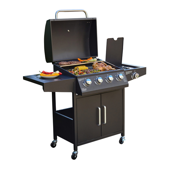
- Page 1 INSTRUCTION MANUAL Neo 5 Burner (4+1) Gas BBQ with Gas Regulator Kit & Rain Cover GAS-5BURN-BBQ For any issues please feel free to contact us, we are always happy to help. Email: support@neodirect.com Telephone: 01133 502 501...
- Page 2 PARTS Please see page 2 for detailed part list...
-
Page 3: Safety Instructions
SAFETY INSTRUCTIONS 1. Read the instruction manual carefully before use and keep for future reference. Failure to comply with the instructions can result in death, serious injury or property damage. 2. For outdoor use ONLY! Do not use indoors. 3. Do not use below ground level. 4. -
Page 4: Part List
PART LIST Pic. Pic. M4 *8 screw M5*12 screw Top door M4*nut Bottom door M3*nut M3*10 screw M3*10 self-tap screw... - Page 5 Assembly Note: Please do not tighten the screws and nuts until all assembly steps are completed. M3 * 10 screw x 2 M3*10 st x 2 M3 nut x 2 1. Assemble the left side and right side frame (5&6) to the bottom shelf (7) with 4pcs M5 screws (B).
- Page 6 Assembly 2. Assemble the back shelf (9) to the frames with 4 pcs M5 screws (B).
- Page 7 Assembly 3. Assemble the front beam (8) to the front of frames with 4pcs M5 screws (B).
- Page 8 Assembly 4. Assemble the 4pcs wheels (10&11) to the end of frame legs. Please note: the 2pcs wheels with breaks (10) will always be on the same side.
- Page 9 Assembly 5. The body (1) will slide into the frame legs with 8 pcs pre-assembled M5 screws (See detailed pic.). Tighten the screws after the body is in position. Thermometer (23) is fixed to the lid using its own screw. Make sure all 8pcs screws are pre-assembled before sliding.
- Page 10 Assembly 6. Right side shelf (14) is assembled to the body with 6 pcs M5 screws (B).
- Page 11 Assembly 7. Left side shelf (15) is assembled to the body with 6 pcs M5 screws (B).
- Page 12 Assembly 8. Side burner rotary switch base (16), side burner front plate and side burner valve (inside shelf front plate) are assembled together with 2pcs M4 countersunk screws (A).
- Page 13 Assembly 9a. Side burner (18) is assembled into the side burner shelf with 2 pcs M4 screws (A). Insert the tube to valve connector.
- Page 14 Assembly 9b. One end of ignition (19) is assembled to the side burner shelf with 1pc M4 screw (A) and 1pc M4 nut (D). The other end is assembled to the valve connector.
- Page 15 Assembly NOTICE In order to succeed in lighting the side burner's, make sure the ignition needle's head is direct at one of the side burner's gas holes.
- Page 16 Assembly 10. Decorated knob (17) is assembled to side burner’s front plate. Grate (20) is putted on side burner shelf, with 3 legs slotting into the holes.
- Page 17 Assembly 11. Handles (13) are assembled to front doors (12) with 4pcs M4 screws (A).
- Page 18 Assembly 12. Doors are assembled to the frames’ front legs with top and bottom pins (C&E).
- Page 19 Assembly 13. Warming grid (2), cooking grids (3) and heat tents (4) are fixed into the body.
- Page 20 Assembly 14. Oil cup (21) is assembled to the oil pan. Tighten all screws before use Assembly completed...