Table of Contents

Related Manuals for Panasonic KX-TCA155E


Summary of Contents for Panasonic KX-TCA155E
- Page 1 ORDER NO. KMS0311868C2 DECT Portable Station KX-TCA155E / KX-TCA155CE (for United Kingdom and Europe) 2003 Panasonic Communications Co., Ltd. All rights reserved. Unauthorized copying and distribution is a violation of law.
-
Page 2: About Lead Free Solder (Pbf: Pb Free)
IMPORTANT INFORMATION ABOUT LEAD FREE, (PbF), SOLDERING If lead free solder was used in the manufacture of this product the printed circuit boards will be marked PbF. Standard leaded, (Pb), solder can be used as usual on boards without the PbF mark. When this mark does appear please read and follow the special instructions described in this manual on the use of PbF and how it might be permissible to use Pb solder during service and repair work. -
Page 3: For Service Technicians
1.1. Suggested PbF Solder There are several types of PbF solder available commercially. While this product is manufactured using Tin, Silver, and Copper (Sn+Ag+Cu), you can also use Tin and Copper (Sn+Cu) or Tin, Zinc, and Bismuth (Sn+Zn+Bi). Please check the manufac turer’s specific instructions for the melting points of their products and any precautions for using their product with other materials. -
Page 4: Specification
3. Use a conductive mat on the worktable. 4. Do not touch IC or LSI pins with bare fingers. 3. CAUTION Danger of explosion if battery is incorrectly replaced. Replace only with the same or equivalent type recommendenced by the manufacturer. Dispose of used batteries according to the manufacture’s Instructions. -
Page 5: Battery Charge
5.2. Battery Charge At the time of shipment, the batteries are not charged. Please charge the batteries for about 7 hours before initial use. - When the battery has been completely charged, the charge indicator will change from red to green. - It is normal for the PS and charger to feel warm while the battery is charging. -
Page 6: Battery Information
5.3. Battery Information After your Panasonic batteries are fully charged [at 25°C]: Operation Operating Time While in use (TALK) 10 hrs approx. While not in use (Standby) 120 hrs approx. - Battery charge may be shortened depending on usage conditions and ambient temperature. -
Page 7: Location Of Controls
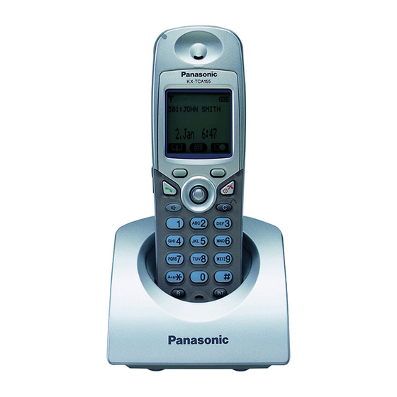
The battery strength icon will then display a correct reading. - Replace both batteries and close the cover then charge the handset for about 7 hours. Please order Panasonic P03P(Ni-MH) batteries. 6. LOCATION OF CONTROLS 6.1. Handset... -
Page 8: Soft Key Display
6.2. Soft Key Display Icons and information shown on the display will vary depending on the state of use. To select an item shown on the display, press the corresponding soft buttons. - Page 9 7. SETTINGS 7.1. Connection - USE ONLY the Panasonic AC ADAPTOR PQLV200CEZ. - USE ONLY the Panasonic AC ADAPTOR PQLV200EZ. 7.2. Settings Menu Chart 7.2.1. Handset...
- Page 10 7.3. Key Lock You can lock the dialling buttons while the PS is in idle status.
- Page 11 7.4. Selecting the Display Language - The display language of both the PS and Business Telephone System can be selected, and both should be set to the same language. Refer to the Business Telephone System User manual for more details. 8.
- Page 12 8.2. Main Menu-while in standby mode 8.3. Sub menu-while in off-hook/during a conversation 8.4. Troubleshooting 9. OPERATIONS...
- Page 13 9.1. Power ON/OFF 9.2. Handset Phonebook 9.3. PBX System Phonebook 9.4. PBX Extension Phonebook 9.5. Character Mode Table...
- Page 14 9.6. Editing - * The Valid digits are “0” through “9”, “ “, “ “, PAUSE. - To change a character or digit, press to highlight it, press...
- Page 15 to delete it, then enter the new character or digit. - To clear an entire line, press and hold - To move the cursor to the left or righ, press respectively. 9.7. Deleting 9.8. Storing an item in the Handset Phonebook...
-
Page 16: Hot Key Dial
- * Press to confirm each entries. - When storing an outside phone number, the line access number will be stored automatically. The line access number must be identical to the PS’s “LineAccess CD” setting (Call Option). 9.9. Hot Key Dial The phone numbers stored in the handset phonebook can be assigned as hot key. - Page 17 10. DISASSEMBLY INSTRUCTIONS 10.1. Handset...
-
Page 18: Charger Unit
Shown in Fig.- To Remove Remove Rear Cabinet Screws (2 × 10)..(A) × 2 Follow the procedure. Main P.C. Board Screw (2 × 8)....(B) × 1 Screws (2 × 8).....(C) × 2 Main P.C. Board 10.2. Charger Unit Shown in Fig.- To Remove Remove Lower Cabinet... -
Page 19: Check Power
Cross Reference: Check Power Bell Reception Check Battery Charge Check Link Check Handset Transmission Check Handset Reception SIGNAL ROUTE 11.1. Check Power 11.1.1. Handset Cross Reference Power Supply Circuit/Reset Circuit... -
Page 20: Check Battery Charge
Note: BBIC is IC1. 11.2. Check Battery Charge 11.2.1. Handset Cross Reference: Check Power Charge Circuit Note: BBIC is IC1. 11.2.2. Charger Unit Cross Reference: Charge Circuit 11.3. Check Link 11.3.1. Handset... - Page 21 Cross Reference...
-
Page 22: Check Handset Transmission
Power Supply Circuit/Reset Circuit Adjustment (Handset) 11.4. Check Handset Transmission Cross Reference: SIGNAL ROUTE 11.5. Check Handset Reception Cross Reference: HOW TO CHECK THE HANDSET RECEIVER SIGNAL ROUTE 11.6. Check Caller ID Cross Reference: SIGNAL ROUTE 11.7. Bell Reception 11.7.1. Handset Cross Reference: Check Link HOW TO CHECK THE HANDSET SPEAKER... -
Page 23: Check Procedure (Handset)
Note: BBIC is IC1. 12. CHECK PROCEDURE (HANDSET) 12.1. Preparation 12.1.1. Equipment Required - DECT tester: Rohde & Schwarz, CMD 60 is recommended. - Frequency counter: it must be precise to be able to measure 1Hz (precision; ±4ppm). Hewlett Packard, 53131A is recommended. - DC power: it must be able to output at least 1A current under 2.4V for Handset, 9V for JIG. -
Page 24: Download Manual
for the connection). 4. Type “doskey”. Note: See the table below for frequently used commands. Command name Function Example rdeeprom Read the data of EEPROM Type “rdeeprom 00 00 FF”, and the data from address “00 00” to “FF” is read out. readid Read ID (RFPI) Type “readid”, and the registered ID is... - Page 25 [1]-(3) Press OK Selected item will be stored Connect the down road jig cable with selected com port (com1 or com2 or ocm3 or com4) 12.3.3. Step [2] Attach download Jig...
- Page 26 12.3.4. Step [3] Select Download file 3]-(1) Download Program Main Menu Push “Reference” to select the dodownload file. (Download Filename tca155vXXX.hex) XXX= Version Name...
- Page 27 12.3.5. Step [4] Download Start [4]-(1) Click “downlod” key [4]-2 Turn the power of target (TCA155) to [OFF] (Keep pressing “OFF” keywhile 2 seconds) Keep pressing “OFF” key until step [4]-6 This operation will not tum the power of target to on. If terget power tums on, check following item.
- Page 28 [4]-(4) Click “Downliad” Communicating PC with Targer. Don’t release the “OFF” key in this step. If release the “OFF key, downloaging will be failed. [4]-(5) Communication check “OK” If communication check become “OK”, Display will show “CRC OK” If communication NG, check step [4]-(3), then try download again. [4]-(6) Downloading Start After several seconds, Dsilaplay shows “Flash Program Start”.
- Page 29 [4]-(7) Downloading Complete If downloading finished, display shows “Download finished successfully!” Click “off” then disconnect the serial jig cable.
-
Page 30: Adjustments (Handset And Charger Unit)
13. ADJUSTMENTS (HANDSET AND CHARGER UNIT) 13.1. Adjustment (Handset) Items Procedure* Adjustment Point 1. Confirm that the voltage between test point “TP12” and GND is 1.8V ± 0.02V. 1.8V Supply TP12 2. Adjust the 1.8V voltage of TP12 executing command “bandgap XX“ (XX is the value). Confirmation 1. - Page 31 Items Procedure* Adjustment Point 1. BBIC Confirmation (Execute the command "getchk"). BBIC 2. Confirm the returned checksum value. Confirmation Connection of checksum value and program number is shown below. 1. Apply 6V between J3(+) and J4(-) with current limit of PSU to 200mA. (E) Charge Control 2.
- Page 32 Items Procedure* Adjustment Point 1. Execute the command "conttx". (I)* BBIC Clock 2. Adjust the frequency of CLK executing the command "setfreq xx (where xx is the Adjusment value)" so that the reading of the frequency counter is 10.368000MHz ± 10Hz. Transmitted Remove the Antenna before starting step from 1 to 4.
- Page 33 Items Procedure* Adjustment Point (L) Frequency Offset Follow steps 1 to 3 of (J) above. Confirmation 4.Confirm that the frequency Offset is < ± 45kHz. (M) Frequency Drift Follow steps 1 to 3 of (J) above. Confirmation 4.Confirm that the frequency Drift is < ± 30kHz/ms.
- Page 34 Items Procedure* Adjustment Point Sensitivity Follow steps 1 to 3 of (J) above. Receiver 4.Set DECT tester power to -88dBm. Confirmation 5.Confirm that the BER is < 1000ppm. Timing Follow steps 1 to 3 of (J) above. Confirmation 4.Confirm that the Timing accuracy is < ± 0.5ppm.
- Page 35 Items Procedure* Adjustment Point RSSI Level Follow steps 1 to 3 of (J) above. Confirmation 4.Set DECT tester power to -81dBm. 5.Execute the command “readrssi“. 6.Confirm that the returned value is 0×11 ± 8 (hex). 7.Set DECT tester power to -63dBm. 8.Execute the command “readrssi“.
- Page 36 Items Procedure* Adjustment Point 1. Link to standard BASE which is connected to Line Simulator. (R) Audio Check and 2. Set line voltage to 48V and line current to 40mA. confirmation 3. Input -45dBm/1KHz to MIC and measure Line output level. 4.
- Page 37 Items Procedure* Adjustment Point 1. Link to standard Base which is connected to Line Simulator. (S) SP phone Audio 2. Set line voltage to 48V and line current to 40mA. check and 3. Set the handset off-hook using SP-Phone key. confirmation 4.
-
Page 38: Adjustment Standard (Handset)
13.2. Adjustment Standard (Handset) When connecting the Simulator Equipments for checking, please refer to below. 13.3. Adjustment (Charger Unit) Items Procedure Adjustment Point 1. Connect Charge Contact 12 /2W register between charge+ and charge-. (A) Charging Check 2. Measure and confirm voltage across the regigster is 2.7V ± 0.2V. Note: After the measuring, sock up the solder of TP. -
Page 39: How To Check The Handset Speaker
15. HOW TO CHECK THE HANDSET SPEAKER 1. Prepare the digital voltmeter, and set the selector knob to ohm meter. 2. Put the probes at the speaker terminals as shown below. -
Page 40: How To Check The Handset Receiver
16. HOW TO CHECK THE HANDSET RECEIVER 1. Prepare the digital voltmeter, and set the selector knob to ohm... - Page 41 meter. 2. Put the probes at the receiver terminals as shown below.
-
Page 42: Frequency Table (Mhz)
17. FREQUENCY TABLE (MHz) HANDSET Channel No Transmit Frequency Receive Frequency 1897.344 1897.344 1895.616 1895.616 1893.888 1893.888 1892.160 1892.160 1890.432 1890.432 1888.704 1888.704 1886.976 1886.976 1885.248 1885.248 1883.520 1883.520 1881.792 1881.792 Note: Channel No. 10: In the Test Mode on Handset. 18. -
Page 43: Circuit Operation (Charger Unit)
- Temporary operating parameters (for RF, etc.) 19.2. Power Supply Circuit/Reset Circuit Circuit Operation: When power on the Handset, the voltage is as follows; BATTERY(2.2 V ~ 2.6V: J1) L1, D1, Q2 (1.8V) Q3 (2.7V) Q1 (4.0V) The Reset signal generates IC1 (78) and 1.8V. 19.3. -
Page 44: Signal Route
20.1. Power Supply Circuit The power supply is as shown. 21. SIGNAL ROUTE 22. CPU DATA (HANDSET) 22.1. IC1 (BBIC) - Page 45 Description Connection at Normal mode at Reset P3_7/PD7 LCD_A0 P3_1/PD1 RXDSG P3_5/PD5 SPAMP CD P3_4/PD4 D,I/O MIDI ERQ P3_3/PD3 PAON P3_2/PD2 PSEL RFCLK SYRI VDDRF VSSRF Xtal1 RSSI RSSI RXDA CMPREF OPEN TXDA SYEN SYDA SYCL DAC/ADC2 JACK DETECTION P3_6/PD6 D,I/O MIDI_SRQ UTX/P0_0...
- Page 46 Description Connection at Normal mode at Reset P2_0/PWM0 PWM0 P2_1/PWM1 P2_2/ADC0 EX_RESET P2_3/ADC1 MIDI-CS P2_4/SCL1 LCD-SCLK MIDI_SCLK P2_5/SDA1 LCD-SCLK MIDI_SCLK P2_7/DC_CTRL DC_CTRL DC_I P1_6/PON/INT6n P1_7/CHARGE/ CHARGE INT7n P2_6/stop_charge STOP-CHARGE VBAT3/RINGING VBAT3 DC_stab DC_Sense AVS_sense ADC3 LDO1_sense LDO1_CTRL LDO2_CTRL VBAT2 VBAT1 AVS2 AVD2 LSR+/REF...
-
Page 47: Eeprom Layout (Handset)
23. EEPROM LAYOUT (HANDSET) 23.1. Scope The purpose of this section is to describe “layout of the EEPROM (IC10) KX-TCA155 Handset”. The EEPROM contains hardware, software, and user specific parameters. Some parameters are set during production of the handset e.g. crystal oscillator adjustment at 0057, some are set by the user when configuring the handset e.g. - Page 48 Address Initial EEPROM Name Description Default value (0x0000 Type ~0x004F) EEP_LowVoltage Number of ADC step for battery 0x30 low (Not Used) EEP_DspSdt2Level DSP Parameter SideTone2 0xFF, 0x7F, 0x00, 0x0C Main:SideTone2 Main route level MictoRcv:SideTone2 MIc to Receiver level EEP_DspToneLevel DSP Parameter ToneLevel 0xFF, 0x7F, 0xFF, 0x7F Talk:Tone Level in Talk mode...
- Page 49 Address Initial EEPROM Name Description Default value (0x0000 Type ~0x004F) EEP_DspHAGC DSP Parameter HAGC 0xFF, 0x7F, 0x00, 0x20, ToSpAgcmax:HAGC To Sp Ag cmax 0x00, 0x00, 0x00, 0x00, ToSpAgcmin:HAGC To Sp Ag cmin 0x00, 0x20, 0xED, 0x00, ToSpAgcoffcntini:HAGC To Sp Ag coffcntini 0x15, 0x7F, 0x78, 0x7F,...
- Page 50 Address Initial EEPROM Name Description Default value (0x0000 Type ~0x004F) EEP_Seiden LCD static electric command 0x01 output cycle Unit: 640 msec Defaults to 640 msec EEP_LcdWakeupCnt Display Low Duty Wake up Count 0x8D Unit: 640 msec Defaults to 90 sec EEP_LedPwmValue Setting value of PWM for LED 0x20, 0x70,...
- Page 51 Address Initial EEPROM Name Description Default value (0x0000 Type ~0x004F) EEP_Reset_Ctrl Reset or Fatal control when 0xFF software error. 00: Reset other than 00: Fatal stop EEP_BatteryCapacity Bat. Capacity, 0x00, 0x00 The battery can be brought up to [mAh*100] EEP_EEToneConfig Tone Option Data 0x51 Bit 0:Keytone on/off00 - 0000 = Off...
- Page 52 Address EEPROM Name Description Default value Initial (0x0000 Type ~0x027F) EEP_RssiComp1 Offset to be subtracted from ADC- 0x17 value. Measured RSSI at -81dBm (0-0x3f) EEP_RssiComp2 Offset to be subtracted from ADC- 0x24 value. Measured RSSI at -63dBm (0-0x3f) EEP_Ipei International Portable Part 0x00, 0x00, Equipment Identities.
- Page 53 (0-0xFF:Error times) Address EEPROM Name Description Default value Initial (0x0000 Type ~0x027F) EEP_RxMuteCrcError Continuous CRC error times for 0x0A the Rx Mute (0-0xFF:Error times) EEP_RxMuteCrcErrorRsc CRC error resource for the Rx 0x43 Mute Bit6:A-CRC Error Bit5:Q1/Q2 Error Bit1:X-CRC Error Bit0:Z-CRC Error EEP_LowDutyP1ClockDiv Clock Div value for P1 active 0x04...
- Page 54 Address EEPROM Name Description Default value Initial (0x0000 Type ~0x027F) EEP_Available_Language Select Available Language 0xFF, 0xFF, 0xFF 0:Disable 1:Enable EEP_PrivateRinger_PreSet Setting PrivateRinger PreSet 0x04 Pattern EEP_AutoRedialConfiguration Auto Redial Configuration 0x01 Bit 0: 0:Disable, 1:Enable Bit1-7: Reserved EEP_AutoRedialRetryTimeout Timeout between auto redial 0x28 attempts.
- Page 55 Address EEPROM Name Description Default value Initial (0x0000 Type ~0x027F) EEP_AudioKeyClickVol Volume step for KeyClickTone 0x02 (PWM) Range 00-22 EEP_AudioDspRingerVolStep Volume step for DSPRinger 0xFF, 0x1F, 0xFF, 0x2F, 0xFF, 0x3F, 0xFF, 0x5F, 0xFF, 0x6F, 0xFF, 0x7F EEP_AudioSicRingerVolStep Volume step for SoundIC (ML2860) xF5, 0xF4, 0xF3, 0xF2, 0xF1, 0xF0...
- Page 56 Address EEPROM Name Description Default value Initial (0x0000 Type ~0x027F) EEP_SPPhone_Current_L Power AMP & SP Phone LED 0x12 current.Vol Low. Additional current in talk by SP Phone at Volume Low. i.e. 100mA -MacCurrent EEP_MaxCapacity_Nicd Max. capacity. Ni-Cd 0x98, 0x3A the battery can be brought up to [mAh*60] EEP_MaxCapacity_NiMH Max.
- Page 57 Address EEPROM Name Description Default value Initial (0x0000 Type ~0x027F) EEP_Actual_Current_TrickleL Actual Charge Current for Trickle 0x19 (Low Cap) i.e. 0.05 * 250 = 12 EEP_Batt_Icom Saved Battery Icom 0x01 EEP_Least_Charge_Time Least charge time 0x05 unit is minit EEP_Charge_Interval Charge interval Time 0x64, 0x00 EEP_MaxVoltage Number of ADC step for battery...
- Page 58 Address EEPROM Name Description Default value Initial (0x0000 Type ~0x027F) EEP_AfeSpPhone Analog Front End Setting for 0x27 Handset SpPhone Mode Bit0-3:Mic_Gain: 1111 (+30dB) ~ 0000 (0dB) Bit4-6:Lsr_Att: 000 (+2dB) ~ 111 (- 12dB) Bit7:Don’t Care EEP_Dspaec Dsp AEC Activate bit 0x01 bit0:AEC_CLR_LEARN_DATA (1: Enable/0:Disable)
- Page 59 Address EEPROM Name Description Default value Initial (0x0000 Type ~0x027F) EEP_DspEq2 DSP Paramefer Voice Equalizer2 0x00, 0x40, (each 2Byte) 0x00, 0x00, 0x00, 0x00, C0:Equalizer2 Pfill C0 0x00, 0x00, C1:Equalizer2 Pfill C1 0x00, 0x00, C2:Equalizer2 Pfill C2 0x40, 0x00, C3:Equalizer2 Pfill C3 0x50, 0x00, C4:Equalizer2 Pfill C4 0x40, 0x00,...
- Page 60 Address EEPROM Name Description Default value Initial (0x0000 Type ~0x027F) EEP_HandsetNumber HandsetNumber each 0xFF, 0xFF, Subscription. 0xFF, 0xFF, 0xFF, 0xFF, (word x 4subs) 0xFF, 0xFF EEP_Subscription0 GAP Subscription Data. Storage All 0x00 for 4 subscriptions each with 53bytes. <Subscription> 12E : SUB_boAssignedIPUI 12F : SUB_abIPUI[14] 13D : SUB_abPARK[5] 142 : SUB_abSARI[4]...
- Page 61 Address EEPROM Name Description Default value Initial (0x0000 Type ~0x027F) EEP_Ulconfih03 User_Setting Data 0x20 Bit0:Any Key Answer 0:OFF 1:ON Bit1-2: Auto Answer 0:OFF 1: Internal 2:Int & External Bit3 charger ;0 Ringer Setting 1: Ringer Off Bit4-5: Vibration and Ringer Setting 00:Vib6Ring 01:Vib->Ring...
- Page 62 Address EEPROM Name Description Default value Initial (0x0000 Type ~0x027F) 1EC2 EEP_WTMode Walkie Talkie Mode: 0x01 00: Common Mode 01: Group Mode 1EC3 EEP_WTHandsetNo Walkie Talkie Handset Number in 0x01 Group Mode: 01-09: Valid range FF: Handset Number not set. 1EC4 EEP_WTGroupId Walkie Talkie Group Id in Group...
- Page 63 Address EEPROM Name Description Default value Initial (0x0000 Type ~0x027F) 1EEF EEP_Language User_Setting Language 0x01 GERAM:0 ENGLISH:1 SPANISH:2 NORWEGIAN:3 FRENCH:4 ITALIAN:5 DENISH:6 DUTCH:7 SWEDISH:8 FINNISH:9 GREEK:10 TURKISH:11 HUNGARIAN:12 PORTUGUESE:13 RUSSIAN:14 1EF0 EEP_SmsEatoniLanguage Eatoni Setting Language 0x01 GERAM:0 ENGLISH:1 SPANISH:2 NORWEGIAN:3 FRENCH:4 ITALIAN:5 DENISH:6 DUTCH:7 SWEDISH:8 FINNISH:9...
-
Page 64: How To Replace Flat Package Ic
Address EEPROM Name Description Default value Initial (0x0000 Type ~0x027F) 1FEE EEP_AutoAnsDelay Auto Answer Delay 0x06 0x05-0x14 (Delav Time (SEC)) 1FEF EEP_TruncCd Tranc Access Code 0x00, 0x00, 0x00, 0x00, 4Byte *3 CODE 0x00, 0x00, 4Byte (BCD)= 1st bvte:Length /2nd- 0x00, 0x00, 4th bvte:Acccess Code 0x00, 0x00, 0x00, 0x00,... -
Page 65: Cabinet And Electrical Parts Location
2. Apply flux to all of the pins on the IC. 3. Being careful to not unsolder the tack points, slide the soldering iron along the tips of the pins while feeding enough solder to the tip so that it flows under the pins as they are heated. 24.3. - Page 66 26. CABINET AND ELECTRICAL PARTS LOCATION (CHARGER UNIT)
-
Page 67: Accessories And Packing Materials
27. ACCESSORIES AND PACKING MATERIALS... -
Page 68: Terminal Guide Of Ics, Transistors And Diodes
28. TERMINAL GUIDE OF ICS, TRANSISTORS AND DIODES 28.1. Handset... -
Page 69: Charger Unit
28.2. Charger Unit 29. REPLACEMENT PARTS LIST 1. RTL (Retention Time Limited) Note: The marking (RTL) indicates that the Retention Time is limited for this item. After the discontinuation of this assembly in production, the item will continue to be available for a specific period of time. -
Page 70: Iso Code (Example: Abs-94Hb) Of The Remarks Column Shows Quality Of The Material And A Flame Resisting Grade About Plastics
4. ISO code (Example: ABS-94HB) of the remarks column shows quality of the material and a flame resisting grade about plastics. 5. RESISTORS & CAPACITORS Unless otherwise specified; All resistors are in ohms ( ) K=1000 , M=1000k All capacitors are in MICRO FARADS ( F)P= *Type &... - Page 71 PQJC10057Z BATTERY TERMINAL A PQJC10058Z BATTERY TERMINAL B PQKE10357Z1 COVER, EARPHONE PQKF10583Y CABINET COVER ABS-HB PSGT2494Z NAME PLATE (for KX-TCA155E) PSGT2479Z NAME PLATE (for KX-TCA155CE) PSHX1220Z PLASTIC PARTS BATTERY COVER SHEET PQHS10561Y SPACER BATTERY COVER PQKK10134Y LID, BATTERY ABS-HB 29.1.2. Main P.C.Board Parts Ref.
- Page 72 Ref. No. Part No. Part Name & Description Remarks G1C100MA0072 COIL (CRYSTAL OSCILLATORS) H0D103500002 CRYSTAL OSCILLATOR H2D600400004 CRYSTAL OSCILLATOR (RESISTORS) ERJ6RSJR10V ERJ3EKF6802 ERJ3EKF1803 180K ERJ3GEYJ153 ERJ3GEYJ471 ERJ3GEYJ103 ERJ3GEYJ224 220K ERJ3GEYJ562 5.6K ERJ3GEYF203 ERJ3GEYF103 ERJ3GEYJ393 ERJ3GEYJ330 ERJ3GEYJ100 ERJ3GEYJ470 ERJ3GEYJ121 ERJ3GEYJ102 ERJ3GEYJ102 ERJ3GEYJ474 470K ERJ3GEYJ331...
- Page 73 Ref. No. Part No. Part Name & Description Remarks ERJ3GEY0R00 ERJ3GEYJ223 ERJ3GEYJ681 ERJ3GEYJ100 ERJ3GEY0R00 ERJ3GEYJ103 (CAPACITORS) ECEV0JA331 ECST0JY106 ECUV1C104KBV 0.1 ECUV1H100DCV 10P ECST0JY106 ECUV1H100DCV 10P ECUV1A224KBV 0.22 ECUV1C683KBV 0.068 ECUV1C104KBV 0.1 ECUV1A105KBV 1 ECUV1C104KBV 0.1 ECUV1C104KBV 0.1 ECUV1C105ZFV ECUV1C104KBV 0.1 ECUV1H100DCV 10P ECUV1H102KBV 0.001 ECUV1C104KBV 0.1...
- Page 74 Ref. No. Part No. Part Name & Description Remarks ECUV1C104KBV 0.1 ECUV1A105ZFV ECUV1A475KB ECUV1A105KBV 1 ECUV1A475KB ECUV1H562KBV 0.0056 ECUV1H020CCV 2P ECUV1H020CCV 2P ECUV1H020CCV 2P F1G1H100A420 ECUV1C683KBV 0.068 ECUV1H020CCV 2P ECUV1C104KBV 0.1 ECUV1C104KBV 0.1 ECUV1C104KBV 0.1 ECUV1H100DCV 10P ECUV1H100DCV 10P PQCUV1A225ZF ECUV1H020CCV 2P ECUV1H020CCV 2P ECUV1C105ZFV...
-
Page 75: Fixtures And Tools
JACK (RESISTORS) ERJ1WYJ220 ERJ1WYJ270 29.3. Accessories and Packing Materials Ref. No. Part No. Part Name & Description Remarks PQLV200EZ AC ADAPTOR (for KX-TCA155E) PQLV200CEZ AC ADAPTOR (for KX-TCA155CE) PQKE10355Z4 HANGER, BELT CLIP PC+ABS-HB PSQX2997ZCD CD-ROM PSQX3027Z QUICK GUIDE (for KX-TCA155E) -
Page 76: Circuit Board (Charger Unit)
33.1. Component View 33.2. Flow Solder Side View 34. CIRCUIT BOARD (CHARGER UNIT) 34.1. Component View 34.2. Flow Solder Side View H / KXTCA155E / KXTCA155CE /... - Page 77 12Ω/2W Digital Volt Meter DC Power Supply 6V...
- Page 78 BBIC CS 2 RESET 96X64 LCD-BACK LIGHT AOUT (Blue) 49 24 23 SCLK MIDI 21 SRQ KEY-BACK LIGHT (Green) 20 ERQ 33, 34 SP-PHONE LED 30 CLK (Red) LOGIC IC CHARGE LED (Red and Green) 6.00MHz KX-TCA155E/KX-TCA155CE BLOCK DIAGRAM (HANDSET)
- Page 79 115KHz TP10 TP11 TP12 +1.8V Charge Current 4.0V DC 2.7V DC 1.8V DC +2.7V 47uH BATTERY+ BATTERY- R57 68 N.M. RX-AF (Speaker phone) TP16 CHARGE+ RX-AF (Handset) 10uH POWER CHARGE- 330R 10uH 100R TX-AF Beep signal (When ON Charge) 470K 2.8V 1sec cycle +1.8V...
- Page 80 (18) TP13 6 VCC_OC 7 GND (19) SYCL 8 SYCL SYDA 9 SYDA RXDA ROW3 SYEN 10 SYEN CLEAR ROW2 11 GND RXDSG TALK SOFT_A MAIL ROW1 4.7uH SYRI RXDA ROW0 PSEL RX-DATA PAON (20) KX-TCA155E/KX-TCA155CE: SCHEMATIC DIAGRAM (HANDSET) (21)
- Page 81 (18) TP13 6 VCC_OC 7 GND (19) SYCL 8 SYCL SYDA 9 SYDA RXDA ROW3 SYEN 10 SYEN CLEAR ROW2 11 GND RXDSG TALK SOFT_A MAIL ROW1 4.7uH SYRI RXDA ROW0 PSEL RX-DATA PAON (20) KX-TCA155E/KX-TCA155CE: SCHEMATIC DIAGRAM (HANDSET) (21)
- Page 82 DC_PLUG Charge_plus Charge_minus pinL SCHEMATIC DIAGRAM (CHARGER UNIT)
- Page 83 TP10 BATTERY (+) "BATT" (BBIC) (+4V) (SP_amp_IC) SP_TEST2 (+) TP15 IC10 C101 SP_TEST2 SP_TEST1 REV_TEST2 REV_TEST1 BATTERY (-) BBIC: 12 TP12 TP11 SP_TEST1 (-) (10.368 MHz) (+1.8V) (+2.75V) (RF clock) (RF module) KX-TCA155E/KX-TCA155CE CIRCUIT BOARD (HANDSET) Component View...
- Page 84 IC4: 29 (6 MHz) LED10 TALK LED9 LED8 R51 R77 SOFT_A C100 CLEAR MAIL (MIDI-IC) (MIDI-IC) KX-TCA155E/KX-TCA155CE CIRCUIT BOARD (HANDSET) Flow Solder Side View...
- Page 85 CIRCUIT BOARD (CHARGER UNIT) Component View...
- Page 86 CIRCUIT BOARD (CHARGER UNIT) Flow Solder Side View...
- Page 87 Marked...
- Page 88 DC_IN TP11 JTAG CHARGE TP17 TP15 TP29 TP22 TP24 TP20 TP21 TP19 TP14 TP12 Marked...
- Page 89 IC10 Marked...
- Page 90 Marked TALK LED9 SOFT_A CLEAR MAIL...
- Page 91 Marked Marked (Component View) (Flow Solder Side View)
- Page 92 OSCILLO SCOPE AF VOLT LOOP OSCILLO METER SIMULATOR SCOPE AF VOLT DUMMY METER BASE DIGITAL DECT TESTER CMD60 VOLT METER 8Ω TP10 (J) (K) (L) (M) (N) (O) (P) (Q) TP15 (E) (F) DC POWER SUPPLY TP15 J3 CHARGE+ IC10 C101 MIC- MIC+...