Advertisement
Quick Links
RENEWAL PARTS IDENTIFICATION
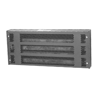
Industrial Wall Mounted Natural Convection
ELECTRIC SHOCK HAZARD. Disconnect all power
before installing or servicing heater. Failure to do
so could result in personal injury or property dam-
age. Heater must be installed by a qualified person
in accordance with the National Electrical Code,
NFPA 70.
1. All wiring should be done in accordance with local codes and the
National Electrical Code by a qualified person.
2. Connect air heaters to same line voltage as on heater nameplate.
3. Check possibility of corrosion if heaters are operated in atmos-
pheres other than air.
4. In general, locate heater approximately 1 foot from the floor, but
not less than 6 inches, for best overall results. Heater, however, can
be located anywhere to meet unique requirements of any particu-
lar application.
© 2010 Chromalox, Inc.
Installation, Operation
and
Space Heater - Type H
Specifications
Output
Model
(kW)
H-1801
1.0
H-1801
1.0
H-2405
1.5
H-2405
1.5
H-2405
1.5
H-2406
2.0
H-2406
2.0
H-2406
2.0
H-2407
3.0
H-2407
3.0
GENERAL INFORMATION
Dimensions (In.)
Voltage
Output
(Vac)
(BTUH)
Width
Height
120
2
20-3/4
7-1/2
240
2
20-3/4
7-1/2
120
2
26-1/2
7-1/2
240
2
26-1/2
7-1/2
480
2
26-1/2
7-1/2
120
4
26-1/2
11-1/4
240
4
26-1/2
11-1/4
480
4
26-1/2
11-1/4
240
4
26-1/2
11-1/4
480
4
26-1/2
11-1/4
5. Heaters are mounted directly on any type of noncombustible sur-
face—masonry, concrete, block, plastered walls, metal framework,
etc.— using appropriate hardware.
6. Standard heaters are mounted in a horizontal position with the ter-
minal end on the left.
The system designer is responsible for the safety
of this equipment and should install adequate
back-up controls and safety devices with their
electric heating equipment. Where the conse-
quences of failure could result in personal injury or
property damage, back-up controls are essential.
4
H
(Supersedes PF495)
161-304509-001
JANUARY, 2003
Wt.
Lbs.
Depth
4-1/2
28
4-1/2
28
4-1/2
30
4-1/2
30
4-1/2
30
4-1/2
32
4-1/2
32
4-1/2
32
4-1/2
32
4-1/2
32
PF495-1
Advertisement

Related Manuals for Chromalox PF495-1


Summary of Contents for Chromalox PF495-1
-
Page 1: General Information
4. In general, locate heater approximately 1 foot from the floor, but not less than 6 inches, for best overall results. Heater, however, can be located anywhere to meet unique requirements of any particu- lar application. © 2010 Chromalox, Inc. Space Heater - Type H Specifications Output... - Page 2 1. Locate heater position on wall. This unit has special baffle plates and vent holes in the cover to ensure sufficient convection currents. Make sure that the heater is mounted so that the mounting label located on the end cover points up (Fig. 1). 2.
- Page 3 ELECTRIC SHOCK HAZARD. Any installation involv- ing electric heaters must be performed by a quali- fied person and must be effectively grounded in accordance with the National Electrical Code to eliminate shock hazard. Reflector Air Space Between Wall and Heat Element HAZARD OF FIRE OR DISCOLORATION OF TEM- PERATURE SENSITIVE FABRICS.
- Page 4 Limited Warranty: Please refer to the Chromalox limited warranty applicable to this product at http://www.chromalox.com/customer-service/policies/termsofsale.aspx. 2150 N. RULON WHITE BLVD., OGDEN, UT 84404 Phone: 1-800-368-2493 www.chromalox.com...