Advertisement
Quick Links
Installation Instructions
RENEWAL PARTS IDENTIFICATION
30" Min.
F
Approx.
4-11/16" Dia.
Mounting Holes
Specifications — Table 1
Heating Capacity
Model
kW
BTUH
VUH-C-05
5
17,000
VUH-C-07 7.5
25,500
9.8
VUH-C-10 10
34,000
* Based on 60˚F entering air.
** For use with drop ceiling only. Installation in a drop ceiling should be in accordance with NFPA-90A and Article 300-22 of (NEC).
*** For instructions on VUH units rated 15-25 kW refer to Bulletin PF451; VUH units rated 30-50 refer to Bulletin PF452.
®
© 2010 Chromalox
, Inc.
and
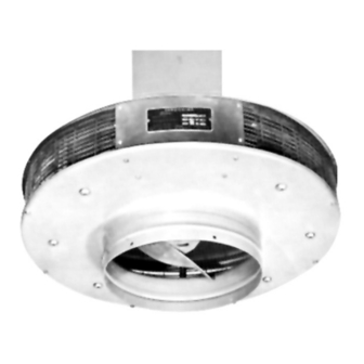
VUH Vertical Unit Heater
12" Min.
H
D
E
M
7' Min.
C L
To Floor
Warm Air
Discharge
Figure 1
Volts
Air Delivery Data
1
3
CFM
FPM
Phase Phase
Temp.˚F*
208
208
240
240
450
703
277
480
208
208
240
240
550
880
277
480
208
208
712
1160
240
240
277
480
SERVICE REFERENCE
DIVISION
SALES
REFERENCE
DATE
4-11/16" Dia.
Mounting
Holes
Position With
Junction Box
Facing Away
From Walls
For Easy Access
4-11/16" Dia.
Mounting
Holes
Max.
Mtg.
Outlet
Height
A
B
(Ft.)
102
10
14
13-1/2
102
12
14
13-1/2
104
14
14
13-1/2
4
SECTION
(Supersedes PF450-4)
161-057822-001
JULY, 2002
30" Min.
17"
A
B
C
Figure 2
Dimensions (In.)
C
D
E
F
H
26
3-1/4
6-5/8
4
7-1/4
26
3-1/4
6-5/8
4
7-1/4
26
3-1/4
6-5/8
4
7-1/4
VUH
PF450-5
12" Min.
8-1/2"
3-7/8"
Drop
Ceiling
Anemostat**
Diffuser
Note:
Knockout Location
See Table 2
For Recommended
Conduit Size.
Mtg.
Weight
(Lbs.)
M
10-5/8
48
10-5/8
48
10-5/8
48
Advertisement

Related Manuals for Chromalox PF450-5


Summary of Contents for Chromalox PF450-5
-
Page 1: Installation Instructions
** For use with drop ceiling only. Installation in a drop ceiling should be in accordance with NFPA-90A and Article 300-22 of (NEC). *** For instructions on VUH units rated 15-25 kW refer to Bulletin PF451; VUH units rated 30-50 refer to Bulletin PF452. ® © 2010 Chromalox , Inc. VUH Vertical Unit Heater... - Page 2 Table 2 - Electrical Data Power Supply Circuit Model Volts Phase (Note 1) VUH-C-05 VUH-C-07 VUH-C-10 Notes: Includes Fan Motor Amps. Use 75˚C Wire - Copper Conductors only. Failure to understand and follow these installation instructions and the “WARNING” notes therein may result in serious per- sonal injury from electrical shock, or from the heater falling due to faulty installation.
-
Page 3: Wiring Diagrams
5. Rough-in wiring to heater. See Table 2 for line amperes, rec- ommended wire size and conduit size. 6. Wire heater per wiring diagram supplied with this instruction sheet. Note: Power relay(s) are provided as standard on all heaters. Prior to operating the heater, verify that the fan hub setscrews are tightened and the push-on clip is secured to assure that the fan blade is securely fas- tened to the motor shaft. - Page 4 118-130480-010 (3) 193-057699-001 NOTES: Number in parenthesis ( ) indicates quanitity required of that part. „ Contactor ˆ Transformer Please refer to the Chromalox limited warranty applicable to this product at http://www.chromalox.com/customer-service/policies/termsofsale.aspx. RENEWAL PARTS IDENTIFICATION (LOCATED ON UNIT NAMEPLATE) Controls Motor Code Part No.