Advertisement
Quick Links
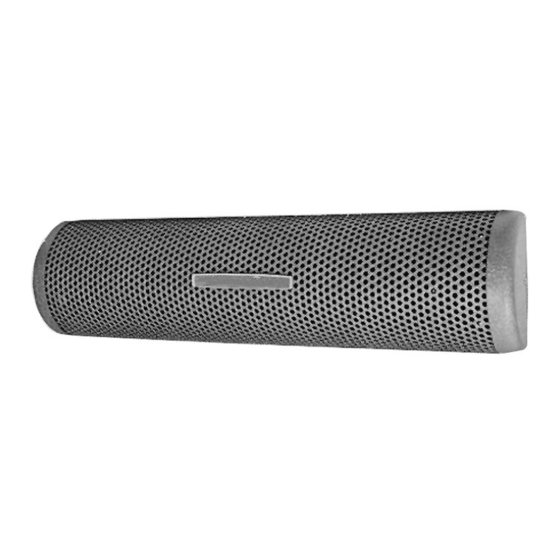
RENEWAL PARTS IDENTIFICATION
Type EH and HVT Electric Utility Heater
NOTICE: Carefully remove heater from carton and check for
shipping damage. Any damage claims should be entered
immediately with the carrier.
FIRE HAZARD. Since heaters are capable of devel-
oping high temperatures, extreme care should be
taken to:
A. Locate on vertical wall with length of heater positioned horizon-
tally. HVT models must be installed with thermostat at right end;
B. Avoid mounting into a wall recess since such mounting interferes
with free air circulation, increases heater temperatures, and pre-
vents proper thermostat operation on HVT models;
C. Mount heaters with a minimum clearance of 24" above floor level
or from adjacent wall;
© 2010 Chromalox®, Inc.
Installation, Operation
and
Type EH
Type HVT*
APRIL, 2003
Specifications – Table A
Model
VoltS
EH-1221
120
EH-1221
240
EH-1251
120
EH-1251
240
HVT-1251*
120
HVT-2411*
120
*HVT models are equipped with a 55°F to 110°F adjustable thermostat.
GENERAL
D. Keep all combustible materials a minimum of 4" from front and
top of heater.
1. Remove screw from each end and remove perforated cover.
2. After feeding electrical wiring through opening in back of heater
(See WIRING section), mount back of heater to wall with four
screws (HVT models-5/16" diameter holes on 5" x 25-7/8") (EH
models 9/32" diameter holes on 5x12-1/2" centers) through back
of heater. Leave one pair of end screws snug, but not tight, to avoid
expansion noise due to binding.
4
EH-HVT
(Supersedes PF421-5)
161-048557-001
A (EH)
A (HVT)
Dim. "A"
WattS
(In.)
250
14
5
/
8
250
14
5
/
8
500
14
5
/
8
500
14
5
/
8
500
28
5
/
8
1000
28
5
/
8
PF421-6
6
3
/
"
4
3
3
/
"
4
Thermostat
(HVT Only)
BTUH
853
853
1706
1706
1706
3412
Advertisement

Related Manuals for Chromalox PF421-6


Summary of Contents for Chromalox PF421-6
- Page 1 HVT models; C. Mount heaters with a minimum clearance of 24” above floor level or from adjacent wall; © 2010 Chromalox®, Inc. Specifications – Table A Model EH-1221...
- Page 2 ELECTRIC SHOCK HAZARD. Disconnect all power before installing or servicing heater. Failure to do so could result in personal injury or property dam- age. Heater must be installed by a qualified person in accordance with the National Electrical Code, NFPA 70. ELECTRIC SHOCK HAZARD.
- Page 3 Model Watts EH-1221 080-016362-002 EH-1251 080-016362-002 HVT-1251 080-016362-003 HVT-2411 1000 080-016362-003 Note: Part numbers suffixed by a number in ( ) indicates the quantity of same part number used. THERMOSTAT REPLACEMENT PROCEDURE See Instruction #1 See Instruction #4 RENEWAL PARTS IDENTIFICATION Heating Elements Front Cover...
- Page 4 Limited Warranty: Please refer to the Chromalox limited warranty applicable to this product at http://www.chromalox.com/customer-service/policies/termsofsale.aspx. 2150 N. RULON WHITE BLVD., OGDEN, UT 84404 Phone: 1-800-368-2493 www.chromalox.com...