Advertisement
Quick Links
Specifications – Table 1
Heating Capacity
Model
kW
VUH-C-30
30
102,000
38.5
VUH-C-40
136,000
39
VUH-C-50
50
170,000
*Based on 60°F entering air.
**For instructions on VUH units rated S-10 kW refer to Bulletin PF450
***For instructions on VUH unites rated IS-25 kW refer to Bulletin PF451
© 2010 Chromalox, Inc.
nstallation, Operation
nd
ENEWAL PA TS IDENTIFICATION
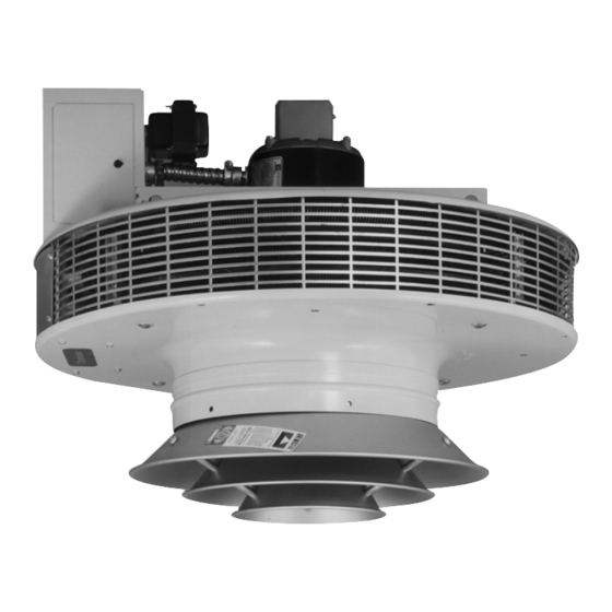
Type VUH Vertical Unit Heater
Figure 1
Volts
Air Delivery
BTUH
1 Phase 3 Phase
CFM
208
–
240
2500
480
240
–
2500
480
–
480
2500
Max.
Mtg.
Outlet
Height
FPM
A
Temp. °F*
(Ft.)
1200
96
33
18-7/8
1200
108
30
18-7/8
1200
120
27
18-7/8
4
(Supersedes PF452-3)
JULY, 2002
Figure 2
Dimensions (In.)
B
C
D
E
F
19
34
10-5/8
15-1/4
3
19
34
10-5/8
15-1/4
3
19
34
10-5/8
15-1/4
3
VUH
PF452-4
161-057824-001
Mtg.
Weight
H
M
(Lbs.)
11
20-3/4
250
11
20-3/4
250
11
20-3/4
250
Advertisement

Related Manuals for Chromalox PF452-4


Summary of Contents for Chromalox PF452-4
- Page 1 170,000 *Based on 60°F entering air. **For instructions on VUH units rated S-10 kW refer to Bulletin PF450 ***For instructions on VUH unites rated IS-25 kW refer to Bulletin PF451 © 2010 Chromalox, Inc. Figure 1 Max. Volts Air Delivery Mtg.
-
Page 2: Installation
Table 2 – Electrical Data Power Supply Circuit Model Volts Phase VUH-C-30 38.5 VUH-C-40 VUH-C-50 Includes Fan Motor Amps Use 90°C Wire - Copper conductors only Standard units have two contactors. Units with separate fan motor control use three contactors. Failure to understand and follow these installation instructions and the “WARNING”... -
Page 3: Wiring Diagrams
Figure 3 170-057688-011 Notes: 1. C1 Must Be Con- nected To 1st Stage Of Thermostat 2. For Single Stage Operation Jumper C1 & C3 Figure 4 170-057688-012 Notes: 1. C2 Must Be Con- nected To 1st Stage Of Thermostat 2. For Single Stage Operation Jumper C2 &... - Page 4 Figure 6 170-057688-014 Notes: 1. C2 Must Be Con- nected To 1st Stage Of Thermostat 2. For Single Stage Operation Jumper C2 & C3 Figure 7 170-057688-015 Notes: 1. C2 Must Be Con- nected To 1st Stage Of Thermostat 2. For Single Stage Operation Jumper C2 &...
- Page 5 Figure 9 170-057688-017 Notes: 1. C2 Must Be Con- nected To 1st Stage Of Thermostat 2. For Single Stage Operation Jumper C2 & C3 Figure 10 170-057688-018 Notes: 1. C2 Must Be Con- nected To 1st Stage Of Thermostat 2. For Single Stage Operation Jumper C2 &...
- Page 6 Fusing „ Contactor ˆ Transformer … Fan Blade › Overheat Cutout Please refer to the Chromalox limited warranty applicable to this product at http://www.chromalox.com/customer-service/policies/termsofsale.aspx. (LOCATED ON UNIT NAMEPLATE) – – Controls Code Description Contactor-24V Coil (30A) 30-00 Contactor-24V Coil (50A)