Comelit KSW3208LU Technical Manual
Hide thumbs
Also See for KSW3208LU:
- Technical manual (58 pages) ,
- User manual (19 pages) ,
- User manual (12 pages)
Table of Contents
Advertisement
Quick Links
Advertisement
Table of Contents

Related Manuals for Comelit KSW3208LU


Summary of Contents for Comelit KSW3208LU
- Page 1 TECHNICAL MANUAL SECUR HUB...
-
Page 2: Table Of Contents
Exit time ....................21 Warning • This Comelit product was designed for use in the creation of security systems in residential, commercial or industrial settings and in public buildings or buildings used by the public. • All activities connected to the installation of Comelit products must be carried out by qualified technical personnel, with careful observation of the indications provided in the manuals / instruction sheets supplied with those products. -
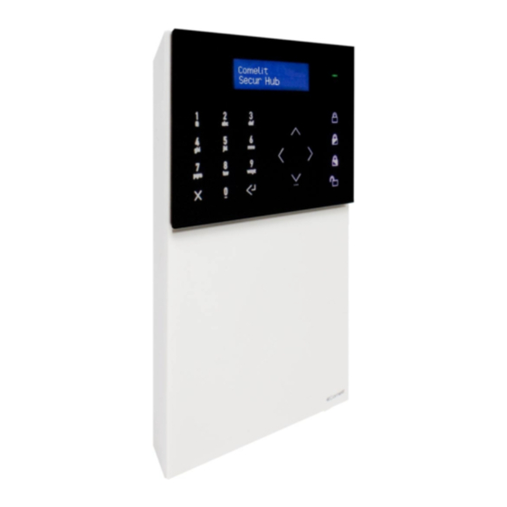
Page 3: Control Panel Description
Control panel description 1. LCD/CAP-SENSE front panel 7. 2G/3G module connector 2. Microphone 8. Tamper switch 3. Micro USB connectors 9. RJ45 Ethernet connector 4. Battery 10. Wired input / output terminal block 5. Battery connector 11. A/C supply terminal block 6. -
Page 4: Installing The Lan Module
Installing the LAN module Installing the 2G/3G module Replacing the backplates... -
Page 5: Choosing The Correct Mounting Position
Choosing the correct mounting position When choosing the correct mounting position for the control panel, take the following factors into account. Functional factors: • When the control panel is on and running, a wireless network is established: avoid fitting the control panel near sources of RF noise, such as large electrical appliances or air conditioners. -
Page 6: Installing The Wall Mounting Backplates
Installing the wall mounting backplates Installing the desk base... -
Page 7: The Front Panel
The front panel 1. 16 x 2-character LCD. 2. LED indicators: green, orange, red. Launch Wizard? 3. Alphanumeric keypad. No:x Ok:↵ 4. Arming/disarming buttons. 5. Back/Cancel/Delete button. 6. Enter/Confirm button. 7. Navigation keypad / menu button. • Green LED: indicates the system is armed (steady) or that it is not ready to arm (flashing). •... -
Page 8: Accessing The Technical Menu
Accessing the technical menu The technical menu contains all the system configuration options. To access the technical menu: f Enter the installer code (default 001961) using the alphanumeric keypad and press the down arrow. Installation Wizard The installation wizard is a guided step-by-step procedure which can be used to set the main functions required to start up a basic system and get it running. -
Page 9: Connect To Wi-Fi
f Enter the APN (Access Point Name) of your service provider; this will be used to enable data traffic for the SIM card. f Press Enter/Confirm to confirm. APN: Connect to Wi-Fi? The second step in the installation wizard allows connection to a Wi-Fi network. f Enter the menu by pressing Enter/Confirm. -
Page 10: Connect To Lan
Connect to LAN? The third step in the installation wizard allows connection to a LAN. f Enter the menu by pressing Enter/Confirm. Connect to LAN? < Ok:↵ > There are two options for setting the IP address of the control panel: •... -
Page 11: Entry/Exit Time
f Use the navigation keys and the alphanumeric keypad to set the correct date. f Press Enter/Confirm to confirm. Set date: 26:06:2018 Entry/exit time? The fifth step in the installation wizard is used to set the entry and exit delays. The entry time is the time available once the entry/exit zone has been opened, allowing the user to disarm the system before an alarm is triggered. -
Page 12: Set Zones
Set zones? The sixth step in the installation wizard is used to register RF sensors. 1. Enter the menu by pressing Enter/Confirm. Set zones? < Ok:↵ > 2. Select the zone to be registered using the navigation keypad and confirm by pressing Enter/Confirm. »... -
Page 13: Set Sounders
5. Select the area to which the zone should be assigned using the navigation keypad and confirm by pressing Enter/Confirm. Area: 6. Select the partition (P1, P2 or P1 + P2) to which the zone should be assigned using the navigation keypad and confirm by pressing Enter/Confirm. -
Page 14: Set Users
3. Enter the device name using the alphanumeric keypad and confirm by pressing Enter/Confirm. Description: Output 01 Set users? The eighth step in the installation wizard can be used to add users and remote controls. f Enter the menu by pressing Enter/Confirm. Set users? <... -
Page 15: Set Phonebook
When you fill in the data fields - such as telephone number or email address - the contact is automatically enabled to receive reports of specified events. Connect App? The tenth step in the installation wizard is used to register accounts relating to the Comelit app on the control panel. 1. Enter the menu by pressing Enter/Confirm. Connect App? <... -
Page 16: Extended Menu
Extended menu When this option is enabled, the installer can see the entire menu. If it is disabled, only the most important menu options are shown within the technical menu structure. The configurations for parameters on a deeper level are hidden to allow more efficient navigation of the menus. - Page 17 The event type (activation or reset), the event description and the time stamp of the events are shown first. f For more information, press the right-hand arrow on the navigation keypad; at this point all the other data will be shown. f To scroll through the log, use the up and down arrows on the navigation keypad.
-
Page 18: Tamper Mask
Load default: if this function is selected, the system will ask you to select one of the following setting options: ◊ default Comelit: this default setting does not conform to EN50131 standards. - Delete access codes? If you confirm, this function restores the user and installer access codes to the factory values. If you do not confirm, the default settings will not result in all user codes being deleted. -
Page 19: Find Rf Device
Find RF device This menu is used to execute an individual “Find” command on registered RF devices, switching on their LEDs so that they can be located and identified. After a device has been found, its LEDs flash for a few seconds and the message “Found!” appears. To find a device: f Move on to the “Find RF device”... -
Page 20: Forced Settings
This menu can be used to search for and download new firmware versions which may be available in the Cloud. Bear in mind that the control panel may be set to install new versions automatically as soon as they are available in the Comelit Cloud. The way in which the update takes place (automatic or manual) is set in the “System options >... -
Page 21: Timing Menu
Timing menu Enter time This is the time available to enter an area via the entry/exit zone and disarm the system. If the entry time is exceeded and no “enter time extension” has been programmed, an alarm is triggered. If a zone is assigned to the “Enter/Exit 1” type, it will observe the “Enter 1 time”... -
Page 22: Sounder Time
Sounder time Menu dedicated to sounder timing options. Sounder time Ind sounder time The following parameters can be set: • Indoor sounder time “Indoor sounder” activation period. The start of this activation can be postponed with the sounder delay. This option can be programmed from 0 to 255 minutes for each system (0=until a valid code is entered). -
Page 23: Sched. Programming
Sched. programming This menu is used to create and enable timed programs which can be used in different ways according to specific user requirements. A scheduled program can be assigned to various entities: a user (to temporarily enable them), an output (a light or other device) or a programmed arming (to arm and disarm the system at set times). - Page 24 • Weekly programming time slot 1 (T.sl.1 Days) can be used to enter the days of the week on which the selected scheduled program is valid. The days of the week can be selected using the L/R arrow and confirmed/removed using Enter. T.sl.1 Days M T W T F S S •...
- Page 25 Scheduled program composition example AREAS TIMER TIME SLOTS WEEKLY PROG. CALENDAR PROG. (OPTIONAL)* 1: 08:30-12:30 Mo Tu We Th Fr Sa 1 total, 2 P1 2: 15:30-19:30 Mo Tu We Th Fr Sa 1 total, 2 P1 3: H24-ON 1 total, 2 P1 4: 08:30-19:30 Mo Tu We Th Fr Sa 15/08/2019 - 30/08/2019...
-
Page 26: Profiles And Codes
Profiles and codes This menu provides access to user profile editing and installer code changes. Access levels The control panel has several access levels which allow users to operate the system with different authorisations. These authorisations can be configured. Access to a user profile makes it possible to check enabled functions, add functions or remove functions. -
Page 27: Devices
Installer 2 • Description: a name can be entered for installer 2. • New code: a new code (between 4 to 6 digits) can be entered, or an existing code edited. Entering an existing code generates an error. Installer code 2 is set by default to 001961. You will be asked to confirm the code, in order to avoid typing errors. •... - Page 28 Register sequence Sequential RF programming mode can be used to register RF sensors. Each device is acquired automatically in sequence with its own ID. After the control panel has acquired the first sensor, it is ready to acquire the next. If several zone slots are already in use, a warning message will appear.
- Page 29 ZONE TYPE TYPE DESCRIPTION Not used The programmed input is not used. It will not trigger any zone alarms or tampering. This zone type generates an instant alarm if it is violated while the system is armed. It also triggers sounder Alarm activation for the time specified in the relevant menu.
- Page 30 ZONE TYPE TYPE DESCRIPTION This type of zone will cause a 24 HR alarm if it is activated when the system/area is disarmed, and will cause 24 HR an intruder alarm when the system/area is armed. The control panel will also send a “24 hour” alarm signal to the alarm receiving centre (if configured).
- Page 31 • Zone attributes The list of possible zone attributes can be consulted using the Up/Down arrows. An attribute can be enabled or disabled using “Enter”. Letters “Y” or “N” refer to an attribute that is enabled or disabled. When a zone does not have applicable options, the text “None”...
- Page 32 • Zone camera This menu entry is used to assign one or more cameras to the zone for video alarm verification. AUX inputs: if you scroll downwards with the arrow key or try to move back in the menu, the display will ask if the user if the user wants to enable the input AUX “B”...
-
Page 33: Wired Zones
Wired zones The two wired zones available on the control panel are configured using this menu. Devices Wired zones Select zone: this menu entry is used to select the zone to be edited. • Description: this menu is used to edit the description of the zone. For detailed information regarding the descriptions of the zones, please refer to Programming for individual RF zones. - Page 34 ◊ Function keys: this menu entry is used to set the actions for the F key. The keypad has 4 Function keys and 4 direction keys. The F and direction keys can perform different actions when pressed. The direction keys can be associated with the number keys pressed, to make 40 combinations.
- Page 35 ◊ Set keypad buzzer This menu is used to set which audible indications the buzzer should generate. The user menu is the same menu as provided for the system. The buzzer is enabled if both the system and keypad settings are enabled. - Entry time: enables buzzer sound during entry time - Exit time: enables buzzer sound during exit time - Alarm: enables buzzer sound in correspondence with alarms...
-
Page 36: Radio Outputs
Radio outputs RF output programming essentially follows the same operating procedure as zone programming. The output device number must be set at the start. After which, the acquisition procedure can begin. Once the output device has been acquired, a description of the output and a type of output can be entered. - Page 37 OUTPUT type Output process This type of output is used to activate the external sounders in the system and will follow the External sounder behaviour defined for external bells This type of output is used to activate the indoor sounders in the system and will follow the Indoor sounder behaviour defined for indoor bells Total arming...
-
Page 38: Wired Outputs
Edit outputs This menu is used to edit the settings for the output, after an output has already been set. For example: if, while using the control panel, the installer needs to edit a configuration for an existing sounder, this menu can be used to select the sounder and move through its configuration. -
Page 39: Rf Repeaters
Used to select the network interface to use for the camera (ETH, WiFi, Access Point) • Camera type Used to select which Comelit camera series is used. Select “Other” if it is not a Comelit camera. If “Other” is selected, you will be asked to enter suitable RTSP strings. Edit CCTV device •... -
Page 40: Areas
Areas The number of areas that the system needs to manage is set here. The menus include the following: Technical menu Areas Number of areas The number of areas managed by the system is set here. The number keys can be used to enter the number directly. Default setting: 1 Areas description Select area... -
Page 41: Communicator
Communicator Technical menu Communicator Directory This menu is used to configure the directory of contacts on the control panel. Recipients can be added, along with a description, type, account number and corresponding protocols. Up to 16 recipients can be saved. Note that more than one type of information (email, phone, ...) can be assigned for each recipient. -
Page 42: Event Send Settings
Event send settings Communications Event send settings • Activations This menu is used to program which event activations should be sent to individual recipients. After selecting this menu, the first group of events is shown at the top of the display (if the FULL MENU option is disabled). There are 16 positions, corresponding to the 16 recipients, at the bottom of the display. -
Page 43: Message Recording
Message recording This menu can be used to customise the pre-recorded voice messages on the control panel. The list of existing messages relating to system events can be consulted from this menu. Selecting a message allows you to listen to, record and delete the message. -
Page 44: Audio Options
◊ Monitoring audio: used to set TWA mode for “Alarm receiving centre” type contacts. - SIA AV-01 - CID - Custom Comelit protocol (not implemented). • Stop calls If the “Stop calls” menu is enabled, the Kissoff key will stop the call queue, preventing the control panel from making any other calls relating to this event. -
Page 45: Send Event Opt
Send event opt. • Mains power fault delay This menu is used to enter a delay before the recipients of the event report are notified of any mains power fault event. The interval can be set between: 1~255 minutes. Communicator Send event opt. - Page 46 • SIA events ◊ [Event group 1-X] codes - Event group X: Event 1(-X) code This menu is used to edit the SIA code sent to the alarm receiving centre for the selected event. • SMS/email header This menu is used to enter the header message used as the initial text or as the email subject for SMS messages and email reports for the control panel.
-
Page 47: Communic. Channels
Communic. channels This menu is used to set all the various communication channels (GSM, TCP-IP, Wi-Fi). Communicator Communic. channels 3G/2G settings ◊ General settings - SIM Number - PIN ◊ Data settings - Data APN - Data username - Data password ◊... -
Page 48: System Options
System options Technical menu System options Arming opt. System options Arming opt. • Forced arm.opt. From here the forced arming option can be selected; this is common to all zones in any area. ◊ Exclude (DEFAULT): this option has the following effect: when the user arms the system, but there are conditions preventing the process from taking place, the system asks whether the user wants to force arming. -
Page 49: Arming Programs
This menu can be used to create, edit and delete arming scenarios in which the arming status of each area can be selected. The scenarios can then be launched using the function keys or the command “Arming program” in the user menu, or via the Comelit app used for system management. -
Page 50: Monitoring Time
Monitoring time The monitoring time can be set for two main sensor families: System options Monitoring • Burglar Alarm This menu entry can be used to set the monitoring time for the sensors and burglar alarm devices. It sets the monitoring fault timeout in the event that there is no valid signal originating from the sensor (monitoring or activation signals). -
Page 51: Robbery Alarm
Robbery alarm This menu entry is used to configure the type of reaction the system has to a robbery alarm command: System options Robbery alarm • Silent al.: in this case no audible or visual signal will be generated, but the corresponding event will be sent to the configured recipients. -
Page 52: Hardware Sett
◊ Trip event: this menu option is used to select the “trip” event that triggers the macro actions. Trip events can be browsed using the Up/Down arrows. The list of possible trip events is: - A valid code with Macro authorisation - Alarms (you can select from all possible alarm types) - Total arm.com. -
Page 53: False Code
False code This menu is used to set how many times an incorrect user code can be entered in the system before resulting in a “False code” sabotage event. The interval can be set between 1 and 10 times. System options False code Alarm reset This menu is used to set the logic to be followed by the control panel when resetting alarm events. -
Page 54: Menu Timeout
Menu timeout This menu is used to set the timeout period before the user menu and the technical menu automatically drop out when no system operations have been taking place. System options Menu timeout • Technical menu Setting for the technical menu (1 to 255 min) •... -
Page 55: Walk Test Opt
Walk Test opt. This menu is used to set which zones will be available for the walk test menu (zone test) within the user menu. The menu also sets which type of confirmation will be provided during the walk test for the zones. System options Walk Test opt. - Page 56 C E R T I F I E D M A N A G E M E N T S Y S T E M S w w w . c o m e l i t g r o u p . c o m Via Don Arrigoni, 5 - 24020 Rovetta (BG) - Italy...