
Related Manuals for Edimax GS-5208P


Summary of Contents for Edimax GS-5208P
- Page 1 Questo manuale d’istruzione è fornito da trovaprezzi.it. Scopri tutte le offerte per Edimax GS-5208PLG o cerca il tuo prodotto tra le migliori offerte di Switch ES-5208P User Manual 10-2015 / v1.0...
-
Page 2: Table Of Contents
Table of Contents Chapter 1 Product Introduction..........................3 1.1 Product Overview ............................3 1.2 Features ................................. 3 1.3 Hardware Description ............................ 3 1.3.1 Front Panel ............................3 1.3.2 Rear Panel ............................5 1.4 Package Contents Preparation Before Installation ..................5 1.4.1 Package Contents .......................... - Page 3 2.6.1 VLAN Mode ............................... 18 2.6.1.1 VLAN Based on Port ..........................18 2.6.2 VLAN Member ............................18 2.6.2.1 VLAN Based on Port ..........................18 2.6.2.2 VLAN Based on Tag ..........................19 2.6.3 Multi to 1 Setting Configuration ....................... 20 2.7 Per Port Counter ............................21 2.8 QoS Configuration ............................
-
Page 4: Chapter 1 Product Introduction
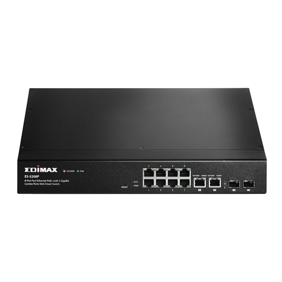
Chapter 1 Product Introduction Thank you for purchasing an Edimax PoE Web Smart Ethernet Switch. Before you install and use the product, please read this manual carefully to make the best use of the product’s functions . 1.1 Product Overview The Edimax ES-5208P is a web-smart switch with 8 Fast Ethernet PoE+ ports and 2 Gigabit Combo ports. - Page 5 The following table describes the interface of the ES-5208P. Interface/Button Description 8 x RJ-45 Ethernet interfaces, 10 M/100 M self-adaptive. Two groups of fiber-copper combo ports. The copper ports are 10 M/100 M/1000 M self-adaptive Ethernet ports and the fiber ports are 9, 10 SFP optical module ports.
-
Page 6: Rear Panel
1.3.2 Rear Panel The rear panel of the switch features the AC power connector: Rear Panel Interface Description The power interface. 100-240VAC 50/60Hz The power input is 100 V ~ 240 V AC, 50 Hz ~ 60Hz. AC Power Connector: Power is supplied through an external AC power adapter. -
Page 7: Choosing The Installation Location
1.4.3 Choosing the Installation Location The ES-5208P can be installed in either of the following ways as required: On the work platform on a rack 1.4.3.1 Installing the ES-5208P on the Work Platform The common way is to install the ES-5208P on a clean work platform. Pay attention to the following precautions: ... -
Page 8: Powering On The Device
1.6.2 Powering On the Device After connecting the power cable, turn on the power switch. When the Power indicator turns on, the system starts to initialize. When other indicators blink three times and the Power indicator is always on in green, the power works normally. -
Page 9: Chapter 2 Web Configuration And Management
Chapter 2 Web Configuration and Management The system does not support the CLI and telnet management. It supports the web management only. This section describes the web configuration and management. 2.1 Preparation Before Login Before accessing the switch, ensure the communication between PC and switch is normal. Check the communication as follows. -
Page 10: Logging In To The Switch
If the PC can read the MAC address of the switch and can ping through the maintenance IP address of the switch, that means the communication of the PC and the switch is normal. 2.2 Logging In to the Switch To login to the web management interface and configure the switch’s settings, connect a computer to the switch using an Ethernet cable. -
Page 11: System Management
2.3 System Management Choose Administrator, and the sub-menus of Administrator are shown as below. 2.3.1 Authentication Configuration Choose Administrator > Authentication Configuration, and the following page appears. Read the Note in the page, and change the user name and password. After proper configuration, click Update to apply the settings and then Reboot the device for the changes to take effect. -
Page 12: System Ip Configuration
2.3.2 System IP Configuration Choose Administrator > System IP Configuration, and the following page appears. In this page, you can set the maintenance IP address of the switch, subnet mask, and gateway. After proper configuration, click Update to apply the settings and then Reboot the device for the changes to take effect. 2.3.3 System Status Choose Administrator >... -
Page 13: Firmware Update
2.3.5 Firmware Update Choose Administrator > Firmware Update, and the following page appears. In this page, enter the login password. Then click Update. A pop up page will appear asking you to select new file for updating the firmware. Caution : When firmware update is in progress, do not shut down the switch. 2.3.6 Reboot the Device Choose Administrator >... -
Page 14: Poe Status
2.4.1 PoE Status Choose PoE> PoE Status and the following page appears. 2.4.2 PoE Setting Choose PoE > PoE Setting and the following page appears. 2.4.3 PoE Power Delay Choose PoE > PoE Power Delay and the following page appears. -
Page 15: Poe Scheduling
2.4.4 PoE Scheduling Choose PoE > PoE Scheduling and the following page appears. 2.4.5 NTP Setting Choose PoE > NTP Setting and the following page appears... -
Page 16: Port Management
2.5 Port Management Choose Port Management, and the submenus of Port Management are shown as below. 2.5.1 Port Configuration Choose Port Management > Port Configuration, and the following page appears. In this page, you can set Tx/Rx Ability, Auto-Negotiation, Speed, Duplex, Pause, Backpressure, and Addr. Learning of port. -
Page 17: Port Mirroring
2.5.2 Port Mirroring Choose Port Management > Port Mirroring, and the following page appears. In this page, you can enable port mirroring service. The packets from source port transmit to destination port. 2.5.3 Bandwidth Control Choose Port Management > Bandwidth Control and the following page appears. After proper configuration, click Update to apply the settings. -
Page 18: Broadcast Storm Control
2.5.4 Broadcast Storm Control Choose Port Management > Broadcast Storm Control and the following page appears. 2.6 VLAN Setting In large networks, routers are used to isolate broadcast traffic for each subnet into separate domains. This switch provides a similar service at Layer 2 by using VLANs to organize any group of network nodes into separate broadcast domains. -
Page 19: Vlan Mode
2.6.1 VLAN Mode 2.6.1.1 VLAN Based on Port Choose VLAN Setting > VLAN Mode, and the following page appears. The default mode is Port Based VLAN. Click Change VLAN mode to change the VLAN mode. Once "Change VLAN mode" is selected, a warning message will appear. Select "Continue" to change the mode or select "Back"... -
Page 20: Vlan Based On Tag
2.6.2.2 VLAN Based on Tag When the VLAN mode is tag, the VLAN Member Setting page is shown as the following figure. The following figure displays the VLAN configuration in the tag mode... -
Page 21: Multi To 1 Setting Configuration
Field Description Select the Vlan ID to be assigned to the VLAN and click on Add to enter the VID. Once the VID is added it will appear in the drop down list. Select the VID from the Dropdown list and then select the desired VLAN Member Port member ports from the Table. -
Page 22: Per Port Counter
2.7 Per Port Counter Choose Per Port Counter, and the Port Counter submenu is shown as below. Choose Per Port Counter > Port Counter and the following page appears. In this page, you can view the packet quantity. Field Description Select it from the drop-down list: Counter Mode Selection... -
Page 23: Qos Configuration
2.8 QoS Configuration All switches or routers that access the Internet, rely on class information to provide the same forwarding treatment to packets in the same class. Class information can be assigned by end hosts, or switches or routers along the path. Priority can then be assigned based on a general policy, or a detailed examination of the packet. However, note that detailed examination of packets should take place close to the network edge so that core switches and routers are not overloaded. -
Page 24: Class Of Service Configuration - 1
The system supports the following three priority modes. First-In-First-Out All-High-before-Low Weight-Round-Robin Low weight: You can select 0 ~ 7 from the drop-down list. High weight: You can select 0 ~ 7 from the drop-down list. 2.8.2 Class of Service Configuration - 1 Choose QoS Setting >... - Page 25 Field Description You can select it from the drop-down list: Option Port: The valid range is 1 ~ 65535. User_Define Mask: The valid range is 0 ~ 255. Override: When the "override" item is selected, the TCP/UDP port QoS Port_based, Tag based, IP TOS_based, CoS listed function previous will be ignored.
-
Page 26: Security
2.9 Security Choose Security, and the sub-menus of Security are shown as below. 2.9.1 MAC Address Binding Choose Security > MAC Address Binding and the following page appears. After MAC address binding is enabled at a port, only devices whose MAC addresses are consistent with the bound MAC address can communicate through the port. -
Page 27: Tcp/Udp Filter
2.9.2 TCP/UDP Filter Choose Security > TCP/UDP Filter and the following page appears. TCP/UDP port filter discards the set protocol packets at the secure WAN port. All ports can be set to secure WAN ports, and the available protocols include FTP, HTTP, and TELNET. -
Page 28: Spanning Tree
2.10 Spanning Tree Choose Spanning Tree, and the sub-menus of Spanning Tree are shown as below. 2.10.1 STP Bridge Settings Choose Spanning Tree > STP Bridge Settings, and the following page appears. -
Page 29: Stp Port Settings
Field Description You can select it from the drop-down list: STP Mode The valid range is 0 ~ 61440. The lower integer value for Bridge Priority precedence indicates the higher priority. And the integer should be a multiple of 4096. The valid range is 1 ~ 10. -
Page 30: Loopback Detection
Speed IEEE Recommended Recommended Range Value 10Mbps 50~600 100Mbps 10~60 1000Mbp 3~10 10GMbps After proper configuration, click Submit to apply the settings. In the mean time, you can view the STP port status. 2.10.3 Loopback Detection: Choose Spanning Tree > Loopback Detection to configure loopback detection on an interface. When loopback detection is enabled and a port receives it’s own BPDU, the detection agent drops the loopback BPDU and places the interface in discarding mode. -
Page 31: Trunking
These parameters are displayed: Field Description Loopback Detection Function Enables/Disables (Default: disable) Auto Wake Up Configures interface automatic loopback release. Wake-Up Time interval Defines the time interval for the port that will be released from the discarding state. Interface status displays a list of ports with loopback detection status. Select “Reset All Ports” option for manual release. - Page 32 Field Description System Priority The valid range is 1 ~ 65535. You can select it from the drop-down list: Link Aggregation Algorithm The system supports three link groups. Link Group 1: It includes the following ports: 1, 2, 3, 4. Member ...
-
Page 33: Dhcp Relay Agent
2.12 DHCP Relay Agent Choose DHCP Relay Agent and the submenu shown as below appears. 2.12.1 DHCP Relay Agent Field Description DHCP relay Select Enable or Disable to start or Stop the DHCP State relay agent respectively. DHCP relay Sets the maximum allowed number in the hops field Hop count limit of the BOOTP/DHCP header. -
Page 34: Vlan Map Relay Agent
2.12.3 VLAN MAP Relay Agent Choose VLAN MAP Relay Agent After proper configuration, click Submit to apply the settings. Click Refresh to refresh the state of link group. 2.13 Configuration Backup and Recovery Choose Backup/Recovery, and the following page appears. In this page, you can download the switch configuration to PC, or upload the configuration file to switch according to the page attention. -
Page 35: Miscellaneous Configuration
2.14 Miscellaneous Configuration Choose Miscellaneous, and the following page appears. In this page, you can enable Aging, VLAN striding and set VLAN uplink. -
Page 36: Snmp Settings
2.15 SNMP Settings Choose SNMP Settings, and the following page appears. In this page, you can configure SNMP related parameters. Field Description Community Name. The community name used by SNMP. Access Right The right of community name. System Description System Contact System related information. -
Page 37: Logout
2.16 Logout Choose Logout, and the following page appears. In this page, the system asks you whether to logout. Click Accept to logout. Click Back to return to the previous page. -
Page 38: Chapter 3 Troubleshooting
Chapter 3 Troubleshooting If a fault occurs, refer to the following table for troubleshooting: Symptom Suggested Solution Check whether the power is correctly The Power indicator connected. is not ON after the Check whether the power switch is system is started turned on. -
Page 39: Chapter 4 Glossary
Chapter 4 Glossary Auto-negotiation: Auto-negotiation is an Ethernet procedure by which two connected devices choose common transmission parameters, such as speed, duplex mode, and flow control. In this process, the connected devices first share their capabilities as for these parameters and then choose the highest performance transmission mode they both support. - Page 40 increase the link speed beyond the limits of any one single cable or port, and to increase the redundancy for higher availability. COS: Class of Service is supported by prioritizing packets based on the required level of service, and then placing them in the appropriate output queue.
- Page 41 COPYRIGHT Copyright Edimax Technology Co., Ltd. all rights reserved. No part of this publication may be reproduced, transmitted, transcribed, stored in a retrieval system, or translated into any language or computer language, in any form or by any means, electronic, mechanical, magnetic, optical, chemical, manual or otherwise, without the prior written permission from Edimax Technology Co., Ltd.
-
Page 42: Federal Communication Commission Interference Statement
Federal Communication Commission Interference Statement This equipment has been tested and found to comply with the limits for a Class B digital device, pursuant to Part 15 of FCC Rules. These limits are designed to provide reasonable protection against harmful interference in a residential installation. - Page 43 EU Declaration of Conformity English: This equipment is in compliance with the essential requirements and other relevant provisions of Directive 1995/5/EC, 2009/125/EC, 2006/95/EC, 2011/65/EC. Français: Cet équipement est conforme aux exigences essentielles et autres dispositions de la directive 1995/5/CE, 2009/125/CE, 2006/95/CE, 2011/65/CE. Čeština: Toto zařízení...
- Page 44 Declaration of Conformity We, Edimax Technology Co., Ltd., declare under our sole responsibility, that the equipment described below complies with the requirements of the European R&TTE directives. Equipment: PoE Web Smart Switch Model No.: ES-5208P, ES-5216P, ES-5224P The following European standards for essential requirements have been followed:...
- Page 45 Notice According to GNU General Public License Version 2 This product includes software that is subject to the GNU General Public License version 2. The program is free software and distributed without any warranty of the author. We offer, valid for at least three years, to give you, for a charge no more than the costs of physically performing source distribution, a complete machine-readable copy of the corresponding source code.
- Page 46 1. You may copy and distribute verbatim copies of the Program’s source code as you receive it, in any medium, provided that you conspicuously and appropriately publish on each copy an appropriate copyright notice and disclaimer of warranty; keep intact all the notices that refer to this License and to the absence of any warranty; and give any other recipients of the Program a copy of this License along with the Program.
- Page 47 5. You are not required to accept this License, since you have not signed it. However, nothing else grants you permission to modify or distribute the Program or its derivative works. These actions are prohibited by law if you do not accept this License.