
Related Manuals for Janome 5270QDC


Summary of Contents for Janome 5270QDC
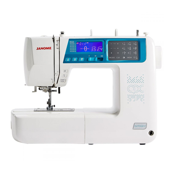
- Page 1 First Edition: 06 March 2020 SERVICE MANUAL & PARTS LIST MODEL: 5270QDC (For Europe only)
-
Page 2: Table Of Contents
INDEX What to do when..........................1 to 3 CHANGING EXTERNAL PARTS FACE COVER ............................4 FREE ARM COVER ..........................5 FRONT COVER ..........................6 to 7 REAR COVER ............................8 MECHANICAL ADJUSTMENT PRESSER BAR HEIGHT ........................9 NEEDLE DROP POSITION ........................10 ADJUSTMENT OF HOOK TIMING .......................11 ADJUSTMENT OF NEEDLE BAR HEIGHT ..................12 CLEARANCE BETWEEN NEEDLE AND TIP OF THE ROTARY HOOK ..........13 FEED DOG HEIGHT ..........................14... -
Page 3: What To Do When
WHAT TO DO WHEN Condition Cause How to fix Reference 1. Skipping 1. Needle is not inserted properly. Insert the needle properly. Stitches 2. Needle is bent or worn. Change the needle. 3. Incorrectly threaded. Rethread. 4. Needle or thread are Use the recommended sewing needle inappropriate for the fabric and thread. - Page 4 WHAT TO DO WHEN Condition Cause How to Fix Reference 3. Breaking 1. Initial sewing speed is Start with medium speed. upper too fast. thread. 2. Thread path is incorrect. Use the proper thread path. 3. Needle is bent or dull. Replace with a new needle.
- Page 5 WHAT TO DO WHEN Condition Cause How to fix Reference 6. Noisy 1. Backlash between hook gear Eliminate the backlash. operation and lower shaft gear is too great. 2. Lower shaft gear is loose. Eliminate the looseness. 3. Inappropriate belt tension. See part removal and replacement P.
-
Page 6: Changing External Parts
CHANGING EXTERNAL PARTS FACE COVER To remove: 1. Remove the setscrews (2 pcs.) q and remove the face cover w. To attach: 2. Follow the above procedures in reverse. -
Page 7: Free Arm Cover
CHANGING EXTERNAL PARTS FREE ARM COVER To remove: 1. Remove the setscrews q (2 pcs.). Move the free arm cover w to the left. Remove the free arm cover. To attach: 2. Follow the above procedures in reverse. -
Page 8: Front Cover
CHANGING EXTERNAL PARTS FRONT COVER (1) To remove: 1. Remove the face cover and free arm cover (see pages 4 and 5). 2. Remove the setscrews A q (2 pcs.). 3. Remove the setscrews B w (2 pcs.) and bed cover e. 4. - Page 9 CHANGING EXTERNAL PARTS FRONT COVER (2) 7. Disengage the front cover and rear cover hooks. 8. Disconnect all the connectors from the circuit board A. NOTE: Do not disconnect the connectors by pulling on cord. To disconnect, grasp the connector, not the cord. 9.
-
Page 10: Rear Cover
CHANGING EXTERNAL PARTS REAR COVER To remove: 1. Remove the face cover and free arm cover (see pages 4 and 5). 2. Remove the setscrews A q (2 pcs.). 3. Remove the setscrews B w (3 pcs.). 4. Remove the setscrews C e (2 pcs.) and bed cover r. 5. -
Page 11: Mechanical Adjustment
MECHANICAL ADJUSTMENT PRESSER BAR HEIGHT The distance between the bottom of the presser foot in up position and the needle plate should be 6.0 mm. 1. Remove the face cover and needle. 2. Lower the feed dog below the needle plate. Place a block 6 mm thick under the presser foot and lower the presser foot lifter w. -
Page 12: Needle Drop Position
MECHANICAL ADJUSTMENT NEEDLE DROP POSITION Set the stitch pattern to “ ”. The standard needle drop position should be at center of the needle plate hole q. Select zigzag stitch “ ”, and set the stitch width at “7.0”. The clearance between the needle and the edge of the needle plate hole should be at least 0.2 mm on either side. -
Page 13: Adjustment Of Hook Timing
MECHANICAL ADJUSTMENT ADJUSTMENT OF HOOK TIMING The amount of ascending travel of the needle bar from its lowest position to the position ( ) where the tip of the rotary hook exactly meets the right side of the needle should be 3.25 to 3.55 mm. 1. -
Page 14: Adjustment Of Needle Bar Height
MECHANICAL ADJUSTMENT ADJUSTMENT OF NEEDLE BAR HEIGHT Before proceeding with this adjustment, check the hook timing (see page 11). The distance between the upper edge of the needle eye and the tip of the hook should be in the range of 1.6 to 2.0 mm when the tip of the hook timing meets right side of the needle in the left needle position ( ) as the needle ascends from its lowest position. -
Page 15: Clearance Between Needle And Tip Of The Rotary Hook
MECHANICAL ADJUSTMENT CLEARANCE BETWEEN NEEDLE AND TIP OF THE ROTARY HOOK * The clearance between the needle and the point of hook should be –0.10 to +0.05 mm. Adjustment procedure: 1. Remove the setscrews A (2 pcs.) on the needle plate, the needle plate and the bobbin holder. 2. -
Page 16: Feed Dog Height
MECHANICAL ADJUSTMENT FEED DOG HEIGHT The highest position of the feed dog should be between 0.80 to 0.90 mm from the surface of the needle plate. 1. Lower the presser foot and turn the power switch on. 2. Turn the handwheel toward you to set the feed dog at the highest position. 3. -
Page 17: Feed Dog Adjustment
MECHANICAL ADJUSTMENT FEED DOG ADJUSTMENT The highest position of the feed dog should be parallel to the surface of the needle plate. If not, adjust as follows. 1. Use a hexagonal socket screw (4x6) q. Insert the hexagonal socket screw (4x6) to the hole w. Tighten the hexagonal socket screw (4x6) as far as it goes. -
Page 18: Top Tension
MECHANICAL ADJUSTMENT TOP TENSION The top tension should be between 65 to 80 grams-force when pulling the thread up in the direction of arrow. * Use polyester sewing thread #50 (White). * If it is not within the above limit, adjust as follows. 1. -
Page 19: Stretch Stitch Feed Balance
MECHANICAL ADJUSTMENT STRETCH STITCH FEED BALANCE To check: 1. Enter the self-diagnostic mode (see below). Attach the Satin stitch foot F. Place a fabric under the presser foot. Lower the presser foot. 2. Press the locking stitch button to start test sew, and check the results (the standard figure length of 5 pieces of figure 8 is 33 to 39 mm). -
Page 20: Adjusting Buttonhole Lever Position
MECHANICAL ADJUSTMENT ADJUSTING BUTTONHOLE LEVER POSITION TO ADJUST THE BUTTONHOLE LEVER GUIDE: 1. Enter the self-diagnostic test of buttonhole sensor mode (see pages 25 and 26. The LCD should display 03 and BH symbol.) 2. Remove the face cover (see page 4) and loosen the setscrew q. 3. -
Page 21: Replacing And Adjusting The Presser Foot Lifter Switch Unit
MECHANICAL ADJUSTMENT REPLACING AND ADJUSTING THE PRESSER FOOT LIFTER SWITCH UNIT To replace: 1. Remove the front cover and rear cover (see pages 5 to 7). 2. Remove the setscrew, replace the presser foot lifter switch. To adjust: 3. Raise the presser foot lifter. Loosen the setscrew. Move the presser foot lifter switch in the direction of the arrows to adjust the position of the switch. -
Page 22: Replacing And Adjusting The Knee Lifter Wire Unit
MECHANICAL ADJUSTMENT REPLACING AND ADJUSTING THE KNEE LIFTER WIRE UNIT (1) TO REPLACE KNEE LIFTER WIRE: To remove: 1. Remove the free arm cover, base plate, front cover and rear cover (see pages 5 to 8). 2. Remove snap rings (2 pcs.). 3. - Page 23 MECHANICAL ADJUSTMENT REPLACING AND ADJUSTING THE KNEE LIFTER WIRE UNIT (2) ADJUSTMENT OF KNEE LIFTER WIRE: Adjustment method NO.1: If the clearance between the knee lifter arm and presser bar supporter is too large (more than 0.3 mm), loosen nuts (2 pcs.) and make part A longer to adjust the clearance. If the clearance between the knee lifter arm and presser bar supporter is too small (less than 0.1 mm), loosen nuts (2 pcs.) and make part A shorter to adjust the clearance.
-
Page 24: Replacing And Adjusting The Needle Threader Holder
MECHANICAL ADJUSTMENT REPLACING AND ADJUSTING THE NEEDLE THREADER HOLDER (1) If the hook of the needle threader holder is damaged, change or adjust the part as follows: To replace: 1. Remove the setscrew to remove the needle threader holder. 2. Prepare the replacement parts (order them as necessary). q 858266009: Link plate 2 w 862627108: Hook holder (unit) e 862626026: Threader plate (unit) - Page 25 MECHANICAL ADJUSTMENT REPLACING AND ADJUSTING THE NEEDLE THREADER HOLDER (2) To adjust: 1. Push down the threader lever and hold it just before the threader hook enters the needle eye. 2. If the threader hook is not aligned vertically with the needle eye, loosen the hexagonal socket screw. Adjust the rotation pin stopper position so that the hook enters into the needle eye.
-
Page 26: Thread Cutter
MECHANICAL ADJUSTMENT THREAD CUTTER The distance between the end of thread cutter plate slit and the edge of moving cutter should be in the range of 0.9 to 1.3 mm. To check: 1. Remove the free arm cover (see page 5). 2. -
Page 27: Self-Diagnostic Test
SELF-DIAGNOSTIC TEST Preparation: 1. Turn the power switch off. 2. Move the bobbin winder spindle to the left. 3. Raise the feed dog. 4. Set the speed control lever to the left. 5. Remove the presser foot and raise the presser foot lifter. 6. - Page 28 SELF-DIAGNOSTIC TEST STEP AND ITEMS T PROCEDURE CORRECT CONDITION DEFECTIVE CONDITION CHECK[ Turn on the power switch while Sewing lamp and LCD backlight lit. Sewing lamp does not lit. FUNCTION OF LCD displays “----”. LCD backlight does not lit. simultaneously pressing the LCD, BUZZER LCD does not display.
- Page 29 SELF-DIAGNOSTIC TEST STEP AND PROCEDURE CORRECT CONDITION DEFECTIVE CONDITION ITEMS TO CHECK LCD displays “05”. Buzzer does not sound. Move the presser foot lifter up and PRESSER down. Presser foot symbol does When the presser foot lifer is lowered, FOOT LIFTER not appear.
- Page 30 SELF-DIAGNOSTIC TEST STEP AND ITEMS TO PROCEDURE CORRECT CONDITION DEFECTIVE CONDITION CHECK Attach the foot control to the LCD displays “08”. The foot control symbol machine. does not appear. FOOT CONTROL Depress the foot control as far as Buzzer does not sound. it goes, then release it.
- Page 31 SELF-DIAGNOSTIC TEST STEP AND ITEMS TO PROCEDURE CORRECT CONDITION DEFECTIVE CONDITION CHECK Turn the handwheel toward you to LCD displays “12”. Thread cutter motor does THREAD raise the needle bar at its highest not work. The thread cutter symbol will blink, and CUTTER position.
-
Page 32: To Display The Version Of The Program
SELF-DIAGNOSTIC TEST Buzzer sounds after few seconds when the self-diagnostic test has been finished. The test result has been determined. CORRECT: Buzzer sounds and LCD displays “00” DEFECTIVE: Caution buzzer sounds and LCD displays the defective part number. See pages 26 to 29 and fix the defective part. The defective part number. -
Page 33: Replacing The Electronic Components
REPLACING THE ELECTRONIC COMPONENTS PRINTED CIRCUIT BOARD A CONNECTION NOTE: Do not disconnect the connectors by pulling on cord. To disconnect, grasp the connector, not the cord. q Printed circuit board F (white) !0 Power switch (white) w Printed circuit board L (white) !1 DC Motor (white) e Program (black) !2 Stitch width motor (green) -
Page 34: Printed Circuit Board A
REPLACING THE ELECTRONIC COMPONENTS PRINTED CIRCUIT BOARD A To remove: 1. Remove the front cover (see pages 6 to 7) 2. Pull out connectors from the printed circuit board A. 3. Remove the setscrews (4 pcs.) and the printed circuit board A. To attach: 4. -
Page 35: Driving Motor
REPLACING THE ELECTRONIC COMPONENTS DRIVING MOTOR To remove: 1. Remove the front cover (see pages 6 and 7). 2. Remove the setscrews (2 pcs.) and the driving motor and the belt. To attach: 3. Install the driving motor and the motor belt. Tighten them with setscrews (2 pcs.) lightly. 4. -
Page 36: Switching Regulator Unit
REPLACING THE ELECTRONIC COMPONENTS SWITCHING REGULATOR UNIT To remove: 1. Remove the front cover and the rear cover (see pages 6 to 8). 2. Remove the setscrews (3 pcs.) and the switching regulator with cords. To attach: 3. Follow the above procedures in reverse. Be sure to connect the connectors (switching regulator connector (5P), controller connector (2P) and auto-off timer switch connector (2P)) to the circuit board A (see page 31). -
Page 37: Cleaning Area Of Thread Cutter And Lower Shaft Gear
CLEANING AREA OF THREAD CUTTER AND LOWER SHAFT GEAR Remove the dust on the area of the thread cutter and the lower shaft gear as follow. 1. Remove the free arm cover (see page 5). 2. Clean the area of the thread cutter and the lower shaft gear. 3. -
Page 38: Key Position Adjustment
KEY POSITION ADJUSTMENT You can adjust the key position when the key sensor is off from the actual key position. Printed the touch panel key position adjustment guide on page 37 to its actual size. Cut off the touch panel guide. Attach the guide on the touch panel with a adhesive tape. -
Page 39: Touch Panel Key Position Adjustment Guide Printed
TOUCH PANEL KEY POSITION ADJUSTMENT GUIDE Print this illustration (guide) to its actual size. -
Page 40: Parts List
MODEL: 5270QDC PARTS LIST... - Page 41 MODEL: 5270QDC PARTS LIST PARTS DESCRIPTION 808601005 Upper shaft (unit) 000111201 Hexagonal socket screw 4x4 000112800 Hexagonal socket screw 4x6 000036201 Washer FT80 508120006 Shaft supporter plate 823110009 Felt 508054101 Shaft supporter plate 820166001 Lower shaft ring 808003001 Upper shaft shielding plate...
- Page 42 MODEL: 5270QDC PARTS LIST...
- Page 43 MODEL: 5270QDC PARTS LIST PARTS DESCRIPTION 814610305 Presser bar base plate (unit) 814001008 Presser bar base plate 808007005 Thread tension release lever 503041007 Thread tension release spring 502024001 Presser foot lifter 000001609 Snap ring E-5 809128006 Presser bar spring adjusting plate...
- Page 44 MODEL: 5270QDC PARTS LIST 23 24...
- Page 45 MODEL: 5270QDC PARTS LIST PARTS DESCRIPTION 809620704 Hook race (whole unit) 809621015 Hook race (unit) 660536004 Hook body (unit) 508118001 Washer 820123006 Hook race shaft 820124007 Hook shaft oil wick (1) 820125008 Hook shaft oil wick (2) 000038409 Washer 508139008...
- Page 46 MODEL: 5270QDC PARTS LIST...
- Page 47 MODEL: 5270QDC PARTS LIST PARTS DESCRIPTION 809608005 Presser foot pressure adjustment (unit) 809018002 Presser foot pressure adjusting set plate 808078203 Presser foot pressure dial 808079008 Adjusting arm 1 808080002 Adjusting arm 2 000002105 Snap ring E-3 000081005 Setscrew 4x8 809616017...
- Page 48 MODEL: 5270QDC PARTS LIST...
- Page 49 MODEL: 5270QDC PARTS LIST PARTS DESCRIPTION 809604322 Rear cover (unit) 809025A06 Rear cover 827503108 Top cover thread guide (unit) 000162001 Setscrew 2.6x5 (B) 650503322 Thread guide (unit) 000014409 Snap ring CS-8 809026003 Carrying handle 809027004 Spool pin 000013800 Snap ring CS-6...
- Page 50 MODEL: 5270QDC PARTS LIST...
- Page 51 MODEL: 5270QDC PARTS LIST PARTS DESCRIPTION 809605057 Front cover (unit) 809030A04 Front cover 808103002 Front cover lid 809031B01 Ornamental panel 1 809032A04 Ornamental panel 2 809033A01 Button 1 809036305 Slide volume 809501007 Touch panel (unit) 809037A05 Touch panel sheet 000014306...
- Page 52 MODEL: 5270QDC PARTS LIST...
- Page 53 MODEL: 5270QDC PARTS LIST PARTS DESCRIPTION 809643208 Knee lift shaft (unit) 809154001 Knee lifter base 1 809155002 Knee lifter base 2 000115205 Setscrew TP 4x6 809156003 Knee lift shaft 000004107 Spring pin 3x14 846297002 Stopper 861072006 Stopper plate 000101105 Setscrew 3x4...
- Page 54 MODEL: 5270QDC PARTS LIST 24 (Continental Europe) 24 (UK)
- Page 55 MODEL: 5270QDC PARTS LIST PARTS DESCRIPTION 809870365 Standard accessories (unit) 822804118 Satin foot (F) (unit) 808852003 Zipper foot (E) (unit) 825817009 Blind hem foot (G) (unit) 822801001 Overedge foot (C) (unit) 822808008 Overcast foot (M) (unit) 858415005 Optic magnifier (20)