Table of Contents
Advertisement
7-DAY or 5/2-DAY PROGRAMMABLE,
OR NON-PROGRAMMABLE THERMOSTAT
I N S TA L L AT I O N A N D O P E R AT I N G I N S T R U C T I O N S
• Please read all of these instructions carefully before beginning
installation.
• Label every wire terminal designation on your existing thermostat wiring
before removing your old thermostat.
• Ignore the color of the wires since they may not comply with any
standard. Please connect wires using the terminal letter designations.
Thank you for your confidence in our product. To obtain the best results from
your investment, please read and follow the installation procedures carefully, and
one step at a time. This will save you time and minimize the chance of damaging
either the thermostat or possibly your heating and cooling system. These
instructions may contain information beyond that which may be required for your
particular installation.
CAUTIONS AND WARNINGS . . . . . . . . . . 2
SYSTEM COMPATIBILITY . . . . . . . . . . . . 3
FEATURES . . . . . . . . . . . . . . . . . . . . . . . 4
TOOLS YOU MAY NEED . . . . . . . . . . . . . . 4
MOUNTING LOCATION . . . . . . . . . . . . . . 5
REMOVE OLD THERMOSTAT . . . . . . . . . . 5
INSTALL THERMOSTAT BASE . . . . . . . . . 6
WIRING INFORMATION . . . . . . . . . . . . . . 7
WIRING DIAGRAMS . . . . . . . . . . . . . . . . 9
COMPLETE THE INSTALL . . . . . . . . . . . 15
WARNING: Use Energizer
Energizer
DURACELL
© 2014 LUX PRODUCTS CORPORATION. ALL RIGHTS RESERVED
All manuals and user guides at all-guides.com
IMPORTANT!
®
or DURACELL
®
is a registered trademark of Eveready Battery Company, Inc.
®
is a registered trademark of The Procter & Gamble Company
T X 1 0 0 E
FRONT PANEL ITEMS . . . . . . . . . . . . . . 17
OPTIONS . . . . . . . . . . . . . . . . . . . . . . . 18
OPERATING INSTRUCTIONS . . . . . . . . . 20
TEMPERATURE PROGRAMS . . . . . . . . . 22
ADVANCED FEATURES . . . . . . . . . . . . . 24
BATTERY REPLACEMENT . . . . . . . . . . . 25
TECHNICAL ASSISTANCE . . . . . . . . . . . 25
LIMITED WARRANTY . . . . . . . . . . . . . . 26
MERCURY NOTICE . . . . . . . . . . . . . . . . 26
®
Alkaline Batteries Only.
52203
Advertisement
Table of Contents

Related Manuals for Lux Products TX100E


Summary of Contents for Lux Products TX100E
-
Page 1: Table Of Contents
WARNING: Use Energizer ® or DURACELL ® Alkaline Batteries Only. Energizer ® is a registered trademark of Eveready Battery Company, Inc. DURACELL ® is a registered trademark of The Procter & Gamble Company © 2014 LUX PRODUCTS CORPORATION. ALL RIGHTS RESERVED... -
Page 2: Cautions And Warnings
All manuals and user guides at all-guides.com CAUTIONS AND WARNINGS: • This thermostat requires batteries to operate and failure or sub-standard performance of the batteries may impair or prevent the correct operation of the thermostat. Use Duracell ® or Energizer ®... -
Page 3: System Compatibility
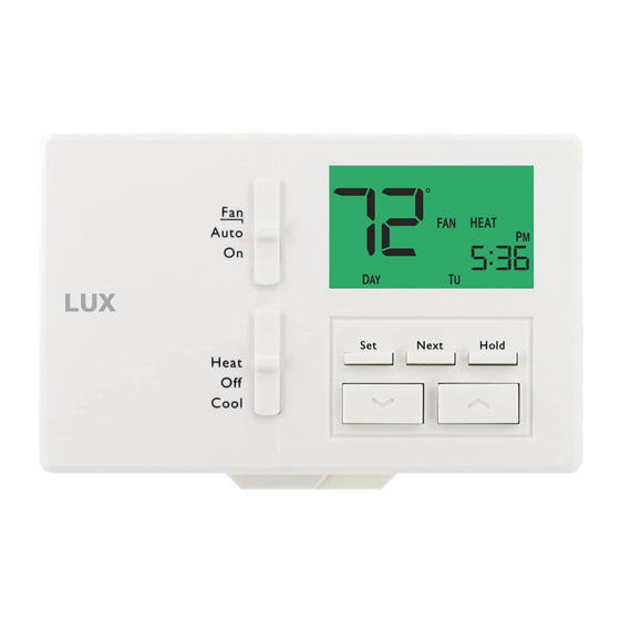
All manuals and user guides at all-guides.com TX100E LCD Display Screen Mode Switch SET, NEXT, Auto and HOLD Buttons Next Hold Heat Cool System Mode Switch UP and DOWN Buttons SYSTEM COMPATIBILITY: The electrical rating for this thermostat is 1.5 Amps per terminal, with a maximum total combined load of 2.0A for all terminals combined. -
Page 4: Features
All manuals and user guides at all-guides.com FEATURES: • 7-day programming, 5/2-day programming, or non-programmable options • All days can be programmed separately • User-selectable periods per day (2 or 4) • Lighted display • Keypad lockout for unauthorized users •... -
Page 5: Mounting Location
All manuals and user guides at all-guides.com MOUNTING LOCATION: On replacement installations, mount the new thermostat in place of the old one unless the conditions listed below suggest otherwise. On new installations, please follow these general guidelines: 1. Mount the thermostat on an inside wall, about 5 ft. (1.5m) above the floor. 2. -
Page 6: Install Thermostat Base
All manuals and user guides at all-guides.com INSTALL THERMOSTAT BASE: Next Hold Heat Cool HOUSING RELEASE TABS (UNDERNEATH BOTTOM EDGE) 1. Strip wire insulation leaving only 3/8 in. (9.5mm) bare wire ends, and clean off any corrosion present. 2. Fill the wall opening with non-combustible insulation to prevent drafts from affecting the thermostat’s normal operation. -
Page 7: Wiring Information
All manuals and user guides at all-guides.com WIRING INFORMATION: CONNECTING THE WIRES: When attaching the wires to the thermostat, please ensure that the bare wire ends are held ALL the way into the terminal block while the screw is being tightened. - Page 8 All manuals and user guides at all-guides.com WIRING DIAGRAM NOTES: (Important, please read all notes before connecting wires) • If the information provided in the following wiring diagrams does not clearly represent or match your system, please refer to the “TECHNICAL ASSISTANCE” section of this manual, and contact us before removing any of your existing thermostat wiring.
-
Page 9: Wiring Diagrams
All manuals and user guides at all-guides.com WIRING DIAGRAMS: DIAGRAM SYSTEM TYPE / DESCRIPTION PAGE # CONVENTIONAL: HEATING ONLY ..........10 SINGLE-STAGE 2, 3, or 4 WIRES CONVENTIONAL: COOLING ONLY ..........11 SINGLE-STAGE 3 or 4 WIRES CONVENTIONAL: HEATING AND COOLING ........12 SINGLE-STAGE 4 or 5 WIRES CONVENTIONAL:... - Page 10 All manuals and user guides at all-guides.com 2 / 3 / 4 WIRES CONVENTIONAL, NON HEAT PUMP 1-STAGE, HEAT ONLY (INCLUDING MILLIVOLT) OPTIONAL SYSTEM COMMON Factory 24V HEAT RH-RC TRANSFORMER Jumper Wire Installed W1 4 HEATER NOTE: THE BLACK TERMINAL LETTERS ARE TYPICAL, GRAY TERMINAL LETTERS ARE BRAND SPECIFIC...
- Page 11 All manuals and user guides at all-guides.com 3 / 4 WIRES CONVENTIONAL, NON HEAT PUMP 1-STAGE, COOL ONLY OPTIONAL SYSTEM COMMON Factory RH-RC Jumper Wire Installed RC V 24V COOL TRANSFORMER UNIT NOTE: THE BLACK TERMINAL LETTERS ARE TYPICAL, GRAY TERMINAL LETTERS ARE BRAND SPECIFIC...
- Page 12 All manuals and user guides at all-guides.com 4 / 5 WIRES CONVENTIONAL, NON HEAT PUMP 1-STAGE HEAT AND 1-STAGE COOL OPTIONAL SYSTEM COMMON Factory RH-RC TRANSFORMER Jumper Wire Installed W1 4 HEATER UNIT NOTE: THE BLACK TERMINAL LETTERS ARE TYPICAL, GRAY TERMINAL LETTERS ARE BRAND SPECIFIC...
- Page 13 All manuals and user guides at all-guides.com 5 / 6 WIRES CONVENTIONAL, NON HEAT PUMP 1-HEAT / 1-COOL, WITH TWO-TRANSFORMERS OPTIONAL SYSTEM COMMON REMOVE 24V HEAT Factory TRANSFORMER RH-RC Jumper Wire 24V COOL TRANSFORMER W1 4 HEATER UNIT NOTE: THE BLACK TERMINAL LETTERS ARE TYPICAL, GRAY TERMINAL LETTERS ARE BRAND SPECIFIC...
- Page 14 All manuals and user guides at all-guides.com 4 / 5 WIRES HEAT PUMP SYSTEMS 1-HEAT / 1-COOL, WITH NO AUXILIARY / EMERG. HEAT OPTIONAL SYSTEM COMMON Factory RH-RC Jumper Wire Installed RC V TRANSFORMER For Heat-Pumps ONLY, Add Second Jumper Wire HEAT (Supplied) PUMP...
-
Page 15: Complete The Install
All manuals and user guides at all-guides.com COMPLETE THE INSTALL: INSTALL BATTERIES INTO THERMOSTAT: Install two brand new Energizer ® DURACELL ® “AA” size alkaline (only) batteries, into the thermostat’s battery compartment. Ensure the batteries are installed in the proper direction. GAS / ELEC CIRCUIT BOARD OPTION (“G”... - Page 16 All manuals and user guides at all-guides.com B/O CIRCUIT BOARD OPTION (FOR HEAT PUMP APPLICATIONS): This setting is a plastic shorting cap (called a jumper) which determines the operation of the shared B/O wire terminal connection. This jumper must remain installed for a Heat Pump system to be able to provide heating and cooling as needed, and the majority of heat pumps today use the default “O”...
-
Page 17: Front Panel Items
All manuals and user guides at all-guides.com FRONT PANEL ITEMS: HEAT / OFF / COOL, SYSTEM MODE SWITCH: Set this switch to HEAT to control your heating system, and COOL to control your cooling system. The OFF position will disable both the heating and cooling units. AUTO / ON, FAN MODE SWITCH: When this switch is in AUTO, the blower fan (if present in your system) will automatically cycle on and off by itself while heating or cooling is running. -
Page 18: System Configuration And Setup Options
All manuals and user guides at all-guides.com SYSTEM CONFIGURATION AND SETUP OPTIONS: Setup options for how the thermostat will function, along with choosing your particular system type, are performed using a menu on the display screen. TO ACCESS THE SETUP MENU: Move the System Mode switch into the OFF position, and then hold down the SET button for approximately 5 seconds until the screen changes. - Page 19 All manuals and user guides at all-guides.com ITEM #06 (SYSTEM / EQUIPMENT TYPE): [1] (default) Fn=Furnace. This is for the majority of heating systems such as a natural gas furnace or hot water boiler, that are not Heat Pump systems. [2] HP=Heat Pump.
-
Page 20: Operating Instructions
All manuals and user guides at all-guides.com OPERATING INSTRUCTIONS: SET DAY AND TIME: Place the System Mode switch into the OFF position. Press the SET button one time and the backlight will illuminate; press the SET button again and the room temperature will disappear from the screen and the day icon will flash. - Page 21 All manuals and user guides at all-guides.com LCD DISPLAY BACKLIGHT: The display screen is lighted to assist viewing at nighttime, or in locations with low light levels. A press of any button on the front panel will light the display for approximately 10 seconds. Any button presses that occur while the light is on will reset the 10-second timer, causing the screen to remain illuminated for an additional 10 seconds.
-
Page 22: Temperature Programs
All manuals and user guides at all-guides.com TEMPERATURE PROGRAMS: By default, this thermostat has 4 separate program periods for both Heat and Cool mode, they are: MORN, DAY, EVE, and NITE. Each period ends at the start time of the following period. The heat programs are set in HEAT mode, and the cool programs are set in COOL mode. - Page 23 All manuals and user guides at all-guides.com FOR 7-DAY PROGRAMMING OPTION: You will be setting each day individually, one at a time. After any particular day’s program has been set, you will have the ability to copy these values either to just the next day or to the remaining days left in the week (described further below).
-
Page 24: Advanced Features
All manuals and user guides at all-guides.com ADVANCED FEATURES: KEYPAD LOCKOUT: You can lock the front panel buttons to prevent unauthorized tampering of your thermostat settings. TO LOCK THE KEYPAD: Start with the thermostat at rest, and the display backlight NOT illuminated. -
Page 25: Battery Replacement
All manuals and user guides at all-guides.com BATTERY REPLACEMENT: This thermostat is powered by two “AA” Alkaline batteries. The batteries should be replaced AT LEAST once per year to ensure reliable operation (or sooner if “LO BATT” appears in the display screen). The batteries are located on the back of the thermostat’s circuit board. -
Page 26: Limited Warranty
All manuals and user guides at all-guides.com LIMITED WARRANTY: If this unit fails because of defects in materials or workmanship within three years of the date of original purchase, LUX will, at its option, repair or replace it. This warranty does not cover damage by accident, misuse, or failure to follow installation instructions. - Page 27 All manuals and user guides at all-guides.com Auto Next Hold Heat Cool Philadelphia, PA 19112 www.luxproducts.com 856-234-7905...