Table of Contents
Advertisement
Quick Links
Installation and Operation Manual
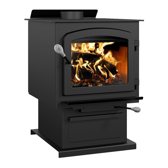
ESCAPE 2100
(DB03129 and DB03131 models)
US Environmental Protection Agency
phase II certified wood stove compliant
with 2020 cord wood standard
Safety tested according to ULC S627,
UL 1482 and UL 737 standards by an
accredited laboratory.
MOBILE
HOME
CONTACT LOCAL BUILDING OR FIRE OFFICIALS ABOUT RESTRICTIONS AND INSTALLATION INSPECTION REQUIREMENTS IN
LOCAL AREA.
READ THIS ENTIRE MANUAL BEFORE INSTALLATION AND USE OF THIS WOOD STOVE. FAILURE TO FOLLOW THESE
INSTRUCTIONS COULD RESULT IN PROPERTY DAMAGE, BODILY INJURY OR EVEN DEATH.
READ AND KEEP THIS MANUAL FOR REFERENCE
Printed in Canada
46108A
Advertisement
Table of Contents

Related Manuals for Drolet ESCAPE 2100


Summary of Contents for Drolet ESCAPE 2100
- Page 1 Installation and Operation Manual ESCAPE 2100 (DB03129 and DB03131 models) US Environmental Protection Agency phase II certified wood stove compliant with 2020 cord wood standard Safety tested according to ULC S627, UL 1482 and UL 737 standards by an accredited laboratory.
- Page 3 It is also highly recommended to register the warranty online at https://www.drolet.ca/en/warranty/warranty-registration/ Registering the warranty will help to quickly find the information needed on the unit. Installation and Operation Manual - Escape 2100 Page 3...
-
Page 4: Table Of Contents
6.3 Glass Door ........................22 6.4 Door ..........................23 6.5 Exhaust System ........................24 PART B - INSTALLATION ......................26 7. Safety Information and Standards ..................26 7.1 Mobile Home ........................26 7.2 Regulations Covering Stove Installation ................26 Page 4 Installation and Operation Manual - Escape 2100... - Page 5 Appendix 7: Air Tubes and Baffle Installation ................46 Appendix 8: Mobile Home Installation ..................48 Appendix 9: Exploded Diagram and Parts List ................ 49 DROLET Limited Lifetime Warranty ................... 52 Dealer: Installer: Phone Number: Serial Number: Installation and Operation Manual - Escape 2100 Page 5...
- Page 6 CERTIFICATION PLATE Page 6 Installation and Operation Manual - Escape 2100...
-
Page 7: Part A - Operation And Maintenance
This product can expose you to chemicals including carbon monoxide, which is known to the State of California to cause cancer, birth defects or other reproductive harm. For more information go to www.P65warnings.ca.gov/ Installation and Operation Manual - Escape 2100 Page 7... -
Page 8: General Information
Optimum overall efficiency at a specific burn rate (LHV). This appliance is officially tested and certified by an independent agency. Tested and certified in compliance with CFR 40 part 60, subpart AAA, section 60.534(a)(1(ii) and ASTM E3053-17 Carbon monoxide. Page 8 Installation and Operation Manual - Escape 2100... -
Page 9: Specifications
CAN/CSA- Z240 MH standard. Tested and certified in compliance with CFR 40 part 60, subpart AAA, section 60.534(a)(1(ii) and ASTM E3053-17. Installation and Operation Manual - Escape 2100 Page 9... -
Page 10: Dimensions
578mm Figure 3: Side view Figure 4: Combustion chamber - side view 9 7/8" 249mm 22 7/8" 19" 581mm 483mm Figure 5: Combustion chamber - front view Figure 6: Door opening Page 10 Installation and Operation Manual - Escape 2100... -
Page 11: Epa Certification Loading
Leave to burn with the primary air control open for approximately 5 more minutes, then close the primary air control halfway. After another 5 minutes, close the primary air control completely for the low burn rate and leave it halfway for the medium burn rate. Installation and Operation Manual - Escape 2100 Page 11... -
Page 12: Materials
Although the stove may be able to heat the main living areas of the house to an adequate temperature, it is strongly recommended to also have a conventional oil, gas or electric heating system to provide backup heating. Page 12 Installation and Operation Manual - Escape 2100... -
Page 13: Emissions And Efficiency
Hardwoods are denser than softwoods. Homeowners with access to both hardwood and softwood use both types for different purposes. Installation and Operation Manual - Escape 2100 Page 13... -
Page 14: Log Length
Continually burning green or unseasoned wood produces more creosote and involves lack of heat and dirty glass door. Firewood with a moisture content between 15% and 20% will allow the stove to produce its highest possible efficiency. Page 14 Installation and Operation Manual - Escape 2100... -
Page 15: Operating The Stove
It is against federal regulations to alter this setting or otherwise operate this wood heater in a manner inconsistent with operating instructions in this manual. Before using the stove, install the coil handles located in the user manual kit. Installation and Operation Manual - Escape 2100 Page 15... -
Page 16: The Use Of A Fire Screen
Therefore, the blower speed control can be left at the desired setting. Page 16 Installation and Operation Manual - Escape 2100... -
Page 17: Burning Wood Efficiently
The best is to wrap a sheet on itself, grab the ends of the roll and make a knot. Use four or five sheets of paper tied together and put them on top and around the kindling. Installation and Operation Manual - Escape 2100 Page 17... -
Page 18: Combustion Cycles
This is especially true if the chimney is on the outside wall of the house. If the door must be opened while the fire is flaming, fully open air control for a few minutes then open the door slowly. Page 18 Installation and Operation Manual - Escape 2100... -
Page 19: Rekindling A Fire
No other waste should be placed in this container. NEVER STORE ASHES INDOORS OR IN A NON-METALLIC CONTAINER OR ON A WOODEN DECK. CENDRES ASHES Installation and Operation Manual - Escape 2100 Page 19... -
Page 20: Air Intake Control
Place the biggest pieces at the back of the firebox and place the rest of the pieces compactly. A densely built fire like this will produce the longest combustion this stove is capable of. Page 20 Installation and Operation Manual - Escape 2100... - Page 21 Open the door slightly and move the log with a poker. Turn it over and create a passage for the air below, making a trench with the coal bed. Add small pieces of wood to restart the combustion. Installation and Operation Manual - Escape 2100 Page 21...
-
Page 22: Maintenance
Do not clean the glass when the stove is hot. Do not abuse the glass door by striking or slamming shut. Do not use the stove if the glass is broken. Page 22 Installation and Operation Manual - Escape 2100... -
Page 23: Door
The test must be performed all around the door. If the paper slips out easily anywhere, either adjust the door or replace the gasket. Installation and Operation Manual - Escape 2100 Page 23... -
Page 24: Exhaust System
Smouldering, smoky fires can quickly cause a thick layer of creosote to form. When the stove is operated properly, the exhaust from the chimney is mostly clear and creosote builds up more slowly. Page 24 Installation and Operation Manual - Escape 2100... - Page 25 Do not use the appliance again until the stove and its chimney have been inspected by a qualified chimney sweep or a fire department inspector. Installation and Operation Manual - Escape 2100 Page 25...
-
Page 26: Part B - Installation
It is recommended to note the stove serial number on page 5 of this manual since it will be needed to precisely identify the version of the appliance in the event replacement parts or technical assistance is required. Page 26 Installation and Operation Manual - Escape 2100... -
Page 27: Clearances To Combustible Material
For a safe way to reduce clearances refer to section «8.3 Reducing Clearances Safely» 48" 36" 122 cm 92 cm 84" (L) 213 cm Figure 10: Clearances - Top Figure 9: Clearances - Side Figure 11: Clearances - Corner Installation and Operation Manual - Escape 2100 Page 27... -
Page 28: Clearances
6" from combustible materials must be used. Only in this case, the same clearances as a certified double wall pipe connector can be used. Page 28 Installation and Operation Manual - Escape 2100... - Page 29 6" from combustible materials must be used. Only in this case, the same clearances as a certified double wall pipe connector can be used. The pipe distances listed in this table refer to the distances obtained when the stove is installed in accordance with the appliance clearances above mentioned. Installation and Operation Manual - Escape 2100 Page 29...
-
Page 30: Floor Protection
The pipe distances listed in this table refer to the distances obtained when the stove is installed in accordance with the appliance clearances above mentioned. Page 30 Installation and Operation Manual - Escape 2100... -
Page 31: Reducing Clearances Safely
The floor protection at the back of the stove is limited to the stove’s required clearance if such clearance is smaller than 8 inches (203 mm). Only required under the horizontal section (Ho) of the connector. Must exceed each side of the connector by at least 2 inches (51 mm). «Figure 9: Clearances - Side» Installation and Operation Manual - Escape 2100 Page 31... - Page 32 Mounting hardware must not be located closer than 8" (200 mm) from the vertical centre line of the appliance. G) Edge clearance for ceiling shields to side and back walls: 3" (75 mm). Shield extension beyond each side of the appliance: 18" (450 mm). Page 32 Installation and Operation Manual - Escape 2100...
- Page 33 Brick, with a minimum of 24 gauge (0.61 mm) sheet metal backing, spaced out at least 1" (25 mm)* by non-combustible spacers 12" (305 mm) * In Canada this space can be ⅞" (21 mm). Installation and Operation Manual - Escape 2100 Page 33...
-
Page 34: The Venting System
Only components intended for the brand and model of chimney should be used. Never fabricate or substitute parts from other chimney brands. The chimney must be a type suitable for solid fuel. Page 34 Installation and Operation Manual - Escape 2100... - Page 35 Do not downsize the flue to less than 6" (150 mm) unless the venting system is straight and exceeds 25' (7,6 m) in height. When passing through a combustible wall, the use of an insulated listed thimble is required. Installation and Operation Manual - Escape 2100 Page 35...
-
Page 36: Minimum Chimney Height
A reddish glow on the unit and on the chimney components indicates overheating. Excessive temperatures can cause a chimney fire. Figure 13: Good System Design Figure 14: Inferior System Design Page 36 Installation and Operation Manual - Escape 2100... -
Page 37: Supply Of Combustion Air
In some windy conditions, negative pressure near hood may draw hot exhaust gases from the stove to outdoors. Check the outdoor air duct for soot deposits when the full system is cleaned and inspected at least once each year. Installation and Operation Manual - Escape 2100 Page 37... -
Page 38: Chimney Connector
• Minimum clearance from combustible material: 18" (450 mm). The minimum clearance may be reduced by 50%, to 9" (225 mm) if proper heat shield is installed either on the pipe or on the combustible surface. Page 38 Installation and Operation Manual - Escape 2100... - Page 39 Where passage through a wall or partition of combustible construction is desired, the installation shall conform to CAN/CSA-B365, Installation Code for Solid-Fuel-Burning Appliances and Equipment. • The chimney connector must be clean and in good condition. Installation and Operation Manual - Escape 2100 Page 39...
-
Page 40: Appendix 1: Optional Fresh Air Intake Kit Installation
(HVAC type, must meet ULC S110 or UL 181 class 0 or class 1) (B), sold separately. Refer to air intake kit installation instructions for more details. Page 40 Installation and Operation Manual - Escape 2100... -
Page 41: Appendix 2: Optional Fire Screen Installation
Lift the fire screen upwards and push the bottom part towards the stove then let the fire screen rest on the bottom of the door opening. Warning: Never leave the stove unattended while in use with the fire screen. Installation and Operation Manual - Escape 2100 Page 41... -
Page 42: Appendix 3: Optional Blower Installation
Ensure that the blower’s power cord is not in contact with any surface of the stove to prevent electrical shock or fire damage. Do not run the power cord beneath the stove. Page 42 Installation and Operation Manual - Escape 2100... -
Page 43: Appendix 4: Optional Thermodisc Installation
Screw the thermodisc (C) with the screws (D) provided on the back of the stove. The electrical cord of the thermodisc should not touch any surface of the stove to avoid electric shock or fire. Do not run the power cord under the stove. Installation and Operation Manual - Escape 2100 Page 43... -
Page 44: Appendix 5: Removing The Decorative Panels
APPENDIx 5: REMOVING THE DECORATIVE PANELS To remove the decorative panels (A), remove the screws (B) and push forward on the panel to unhook it from the support (C). Page 44 Installation and Operation Manual - Escape 2100... -
Page 45: Appendix 6: Log Retainers Installation
APPENDIx 6: LOG RETAINERS INSTALLATION 2" 2" Installation and Operation Manual - Escape 2100 Page 45... -
Page 46: Appendix 7: Air Tubes And Baffle Installation
Put the baffle in place. Repeat steps 1 and 2 for the three other tubes. To remove the tubes use the above steps in reverse order. Page 46 Installation and Operation Manual - Escape 2100... - Page 47 Note that secondary air tubes (A) can be replaced without removing the baffle board (B) and that all tubes are identical. Installation and Operation Manual - Escape 2100 Page 47...
-
Page 48: Appendix 8: Mobile Home Installation
APPENDIx 8: MOBILE HOME INSTALLATION Screw the base on the floor with the proper hardware. Page 48 Installation and Operation Manual - Escape 2100... -
Page 49: Appendix 9: Exploded Diagram And Parts List
APPENDIx 9: ExPLODED DIAGRAM AND PARTS LIST 25 25 DETAIL A Installation and Operation Manual - Escape 2100 Page 49... - Page 50 POWER CORD 96" X 18-3 type SJT (50 pcs per carton) AC02050 BLOWER ASSEMBLY WITH VARIABLE SPEED CONTROL (UP TO 100 CFM) 44073 CROSSFLOW BLOWER 115V-60Hz-39W 100 CFM 44080 RHEOSTAT WITHOUT NUT (MODEL KBMS-13BV) Page 50 Installation and Operation Manual - Escape 2100...
- Page 51 ROUND CAST IRON ASH PLUG PL70838 ASH PAN PL70879 BRUSHED NICKEL TOP DOOR MOLDING (DB03131 ONLY) PL70880 BRUSHED NICKEL BOTTOM DOOR MOLDING (DB03131 ONLY) AC05959 METALLIC BLACK STOVE PAINT - 342 g (12oz) AEROSOL Installation and Operation Manual - Escape 2100 Page 51...
-
Page 52: Drolet Limited Lifetime Warranty
Shall your unit or a component be defective, contact immediately your DROLET dealer. To accelerate processing of your warranty claim, make sure to have on hand the following information when calling: •... - Page 54 Resale is strictly prohibited. The manufacturer may update St-Augustin-de-Desmaures (Québec), Canada this document from time to time and cannot be responsible G3A 2H3 for problems, injuries, or damages arising out of the use 418-908-8002 of information contained in any document obtained from https://www.drolet.ca/en/ unauthorized sources. tech@sbi-international.com...