Table of Contents
Advertisement
Quick Links
This user's guide describes the operation and use of the TPS6381xEVM evaluation module (EVM). The
EVM is designed to help users easily evaluate and test the operation and functionality of the TPS6381x
buck-boost converter family. The EVM has the output voltage set to 3.3 V or 3.45 V, depending on jumper
setting. The output voltage can be programmed via I
operates with an input voltage between 2.2 V and 5.5 V. The output current can go up to 2.5 A in buck
mode and up to 2 A in boost mode. This document includes setup instructions for the hardware, together
with the schematic and the PCB layout of the EVM. Throughout this document, the abbreviations EVM,
TPS6381xEVM, and the term evaluation module are synonymous with the TPS6381x, unless otherwise
noted.
SLVUBK9A – July 2019 – Revised October 2019
Submit Documentation Feedback
2
C interface between 1.8 V and 5.2 V. The EVM
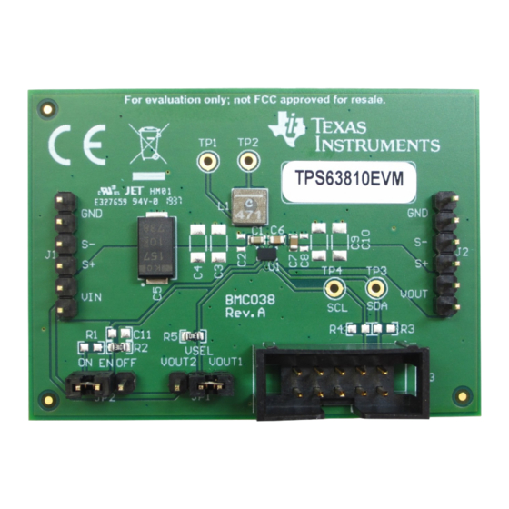
Figure 1. TPS6381xEVM
Copyright © 2019, Texas Instruments Incorporated
User's Guide
SLVUBK9A – July 2019 – Revised October 2019
TPS6381xEVM
TPS6381xEVM
1
Advertisement
Table of Contents

Related Manuals for Texas Instruments TPS6381xEVM


Summary of Contents for Texas Instruments TPS6381xEVM
- Page 1 SLVUBK9A – July 2019 – Revised October 2019 TPS6381xEVM This user’s guide describes the operation and use of the TPS6381xEVM evaluation module (EVM). The EVM is designed to help users easily evaluate and test the operation and functionality of the TPS6381x buck-boost converter family.
-
Page 2: Table Of Contents
TPS6381xEVM ................... TPS6381xEVM PCB - Assembly Layer ..................TPS6381xEVM PCB - Top Layer ............... TPS6381xEVM PCB - Signal Layer 1 (Top View) ............... TPS6381xEVM PCB - Signal Layer 2 (Top View) ................ TPS6381xEVM PCB - Bottom Layer (Top View) .................... -
Page 3: Introduction
Background The TPS6381xEVM uses the TPS6381x integrated circuit (IC) , and is set to 3.3 V or 3.45 V output voltage, depending on jumper setting. The EVM operates with an input voltage between 2.2 V and 5.5 V. -
Page 4: Board Layout
This section provides the TPS6381xEVM board layout and illustrations. Layout Figure 2 through Figure 6 show the component placement and PCB layout of the TPS6381xEVM. TPS6381xEVM SLVUBK9A – July 2019 – Revised October 2019 Submit Documentation Feedback Copyright © 2019, Texas Instruments Incorporated... - Page 5 Board Layout www.ti.com Figure 2. TPS6381xEVM PCB - Assembly Layer Figure 3. TPS6381xEVM PCB - Top Layer SLVUBK9A – July 2019 – Revised October 2019 TPS6381xEVM Submit Documentation Feedback Copyright © 2019, Texas Instruments Incorporated...
- Page 6 Board Layout www.ti.com Figure 4. TPS6381xEVM PCB - Signal Layer 1 (Top View) Figure 5. TPS6381xEVM PCB - Signal Layer 2 (Top View) TPS6381xEVM SLVUBK9A – July 2019 – Revised October 2019 Submit Documentation Feedback Copyright © 2019, Texas Instruments Incorporated...
- Page 7 Board Layout www.ti.com Figure 6. TPS6381xEVM PCB - Bottom Layer (Top View) SLVUBK9A – July 2019 – Revised October 2019 TPS6381xEVM Submit Documentation Feedback Copyright © 2019, Texas Instruments Incorporated...
-
Page 8: Schematic And Bill Of Materials
Schematic and Bill of Materials www.ti.com Schematic and Bill of Materials This section provides the TPS6381xEVM schematic and bill of materials. Schematic Figure 7. TPS6381xEVM Schematic TPS6381xEVM SLVUBK9A – July 2019 – Revised October 2019 Submit Documentation Feedback Copyright © 2019, Texas Instruments Incorporated... - Page 9 USB2ANY adapter using the supplied 10-pin ribbon cable. The connectors on the ribbon cable are keyed to prevent incorrect installation. Figure 8 shows a quick adapter connection overview. SLVUBK9A – July 2019 – Revised October 2019 TPS6381xEVM Submit Documentation Feedback Copyright © 2019, Texas Instruments Incorporated...
-
Page 10: Quick Connection Overview
USB Interface Adaptor Quick Connection Diagram Host Computer 10-Pin Ribbon Cable Interface Adapter USB Cable Green LED Indicates Power EVM Board Figure 8. Quick Connection Overview TPS6381xEVM SLVUBK9A – July 2019 – Revised October 2019 Submit Documentation Feedback Copyright © 2019, Texas Instruments Incorporated... -
Page 11: Gui Home Screen
Settings Screen The Settings screen provides control over the output voltage and operating modes of the TPS6381x. Figure 10. GUI Settings Screen SLVUBK9A – July 2019 – Revised October 2019 TPS6381xEVM Submit Documentation Feedback Copyright © 2019, Texas Instruments Incorporated... -
Page 12: Gui Register Map Screen
Table 4. Device Registers Address Acronym Register Name Section CONTROL Control STATUS Status DEVID Device Identity VOUT1 Output Voltage 1 VOUT2 Output Voltage 2 TPS6381xEVM SLVUBK9A – July 2019 – Revised October 2019 Submit Documentation Feedback Copyright © 2019, Texas Instruments Incorporated... - Page 13 00b = 1 V/ms 01b = 2.5 V/ms 10b = 5 V/ms 11b = 10 V/ms SLVUBK9A – July 2019 – Revised October 2019 TPS6381xEVM Submit Documentation Feedback Copyright © 2019, Texas Instruments Incorporated...
- Page 14 STATUS register is read when the power-not- good condition no longer exists. 0b = power good 1b = a power-not-good event was detected TPS6381xEVM SLVUBK9A – July 2019 – Revised October 2019 Submit Documentation Feedback Copyright © 2019, Texas Instruments Incorporated...
- Page 15 Field Type Reset Description MANUFACTURER 0000b These bits identify the manufacturer (0000b = Texas Instruments). MAJOR These bits identify the major die revision. 00b = A (initial silicon) 01b = B (first major revision) 10b = C (second major revision)
- Page 16 1.8 + (VOUT1 × 0.025). When the RANGE bit = 1, the output voltage in volts is 2.025 + (VOUT1 × 0.025). TPS6381xEVM SLVUBK9A – July 2019 – Revised October 2019 Submit Documentation Feedback Copyright © 2019, Texas Instruments Incorporated...
- Page 17 1.8 + (VOUT2 × 0.025). When the RANGE bit = 1, the output voltage in volts is 2.025 + (VOUT2 × 0.025). SLVUBK9A – July 2019 – Revised October 2019 TPS6381xEVM Submit Documentation Feedback Copyright © 2019, Texas Instruments Incorporated...
- Page 18 Added TPS63811EVM bill of materials ....................• Changed the link to the register map ..................• Removed the pre-production note and errata list Revision History SLVUBK9A – July 2019 – Revised October 2019 Submit Documentation Feedback Copyright © 2019, Texas Instruments Incorporated...
- Page 19 STANDARD TERMS FOR EVALUATION MODULES Delivery: TI delivers TI evaluation boards, kits, or modules, including any accompanying demonstration software, components, and/or documentation which may be provided together or separately (collectively, an “EVM” or “EVMs”) to the User (“User”) in accordance with the terms set forth herein.
- Page 20 www.ti.com Regulatory Notices: 3.1 United States 3.1.1 Notice applicable to EVMs not FCC-Approved: FCC NOTICE: This kit is designed to allow product developers to evaluate electronic components, circuitry, or software associated with the kit to determine whether to incorporate such items in a finished product and software developers to write software applications for use with the end product.
- Page 21 www.ti.com Concernant les EVMs avec antennes détachables Conformément à la réglementation d'Industrie Canada, le présent émetteur radio peut fonctionner avec une antenne d'un type et d'un gain maximal (ou inférieur) approuvé pour l'émetteur par Industrie Canada. Dans le but de réduire les risques de brouillage radioélectrique à...
- Page 22 www.ti.com EVM Use Restrictions and Warnings: 4.1 EVMS ARE NOT FOR USE IN FUNCTIONAL SAFETY AND/OR SAFETY CRITICAL EVALUATIONS, INCLUDING BUT NOT LIMITED TO EVALUATIONS OF LIFE SUPPORT APPLICATIONS. 4.2 User must read and apply the user guide and other available documentation provided by TI regarding the EVM prior to handling or using the EVM, including without limitation any warning or restriction notices.
- Page 23 Notwithstanding the foregoing, any judgment may be enforced in any United States or foreign court, and TI may seek injunctive relief in any United States or foreign court. Mailing Address: Texas Instruments, Post Office Box 655303, Dallas, Texas 75265 Copyright © 2019, Texas Instruments Incorporated...
- Page 24 TI products. TI’s provision of these resources does not expand or otherwise alter TI’s applicable warranties or warranty disclaimers for TI products. Mailing Address: Texas Instruments, Post Office Box 655303, Dallas, Texas 75265 Copyright © 2019, Texas Instruments Incorporated...
- Page 25 Mouser Electronics Authorized Distributor Click to View Pricing, Inventory, Delivery & Lifecycle Information: Texas Instruments TPS63811EVM TPS63810EVM...