Table of Contents
Advertisement
Quick Links
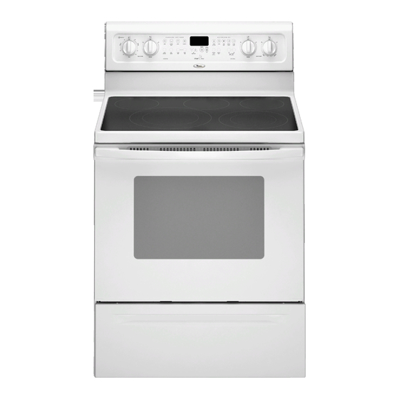
30" (76 CM) FREESTANDING ELECTRIC RANGES
We have provided many important safety messages in this manual and on your appliance. Always read and obey all safety
messages.
This is the safety alert symbol.
This symbol alerts you to potential hazards that can kill or hurt you and others.
All safety messages will follow the safety alert symbol and either the word "DANGER" or "WARNING."
These words mean:
DANGER
WARNING
All safety messages will tell you what the potential hazard is, tell you how to reduce the chance of injury, and tell you what can
happen if the instructions are not followed.
IMPORTANT:
Save for local electrical inspector's use.
W10196158A
INSTALLATION INSTRUCTIONS
Table of Contents
RANGE SAFETY ............................................................................. 1
INSTALLATION REQUIREMENTS................................................ 2
Tools and Parts ............................................................................ 2
Location Requirements................................................................ 2
Electrical Requirements ............................................................... 3
INSTALLATION INSTRUCTIONS.................................................. 4
Unpack Range ............................................................................. 4
Install Anti-Tip Bracket................................................................. 5
Electrical Connection ................................................................... 6
Verify Anti-Tip Bracket Location.................................................. 9
Level Range ................................................................................. 9
Complete Installation ................................................................. 10
Moving the Range......................................................................10
ANTI-TIP BRACKET TEMPLATE ............................................... 11
RANGE SAFETY
Your safety and the safety of others are very important.
A child or adult can tip the range and be killed.
Connect anti-tip bracket to rear range foot.
Reconnect the anti-tip bracket, if the range is moved.
Failure to follow these instructions can result in death or serious burns to children and adults.
You can be killed or seriously injured if you don't immediately
follow instructions.
You can be killed or seriously injured if you don't follow
instructions.
WARNING
Tip Over Hazard
Advertisement
Table of Contents

Summary of Contents for Whirlpool GFE461LVS
-
Page 1: Table Of Contents
INSTALLATION INSTRUCTIONS 30" (76 CM) FREESTANDING ELECTRIC RANGES Table of Contents RANGE SAFETY ................1 INSTALLATION REQUIREMENTS..........2 Tools and Parts ................2 Location Requirements..............2 Electrical Requirements ............... 3 INSTALLATION INSTRUCTIONS..........4 Unpack Range ................4 Install Anti-Tip Bracket..............5 Electrical Connection .............. -
Page 2: Installation Requirements
INSTALLATION REQUIREMENTS Tools and Parts Location Requirements Gather the required tools and parts before starting installation. IMPORTANT: Observe all governing codes and ordinances. Read and follow the instructions provided with any tools listed It is the installer’s responsibility to comply with installation here. -
Page 3: Electrical Requirements
Product Dimensions A. 13" (33.0 cm) max. upper cabinet depth B. 30" (76.2 cm) min. opening width C. For minimum clearance to top of cooktop, see NOTE*. D. 30¹⁄₈" (76.5 cm) min. opening width E. Outlet - 8" (20.3 cm) to 22" (55.9 cm) from either cabinet, 5¹⁄₂"... -
Page 4: Installation Instructions
Electrical Connection If connecting to a 4-wire system: To properly install your range, you must determine the type of This range is manufactured with the ground connected to the electrical connection you will be using and follow the instructions neutral by a link. The ground must be revised so the green provided for it here. -
Page 5: Install Anti-Tip Bracket
3. On Ranges Equipped with Storage Drawers: 2. Place template on the floor in cabinet opening so that the left edge is against cabinet and top edge is against rear wall, Remove the storage drawer. Use a ³⁄₈" drive ratchet to lower molding or cabinet. -
Page 6: Electrical Connection
10. Move range into its final location making sure rear leveling leg 11. If installing the range in a mobile home, you must secure the slides into anti-tip bracket. range to the floor. Any method of securing the range is adequate as long as it conforms to the standards in the “Location Requirements”... - Page 7 Style 2: Direct wire strain relief 4-wire connection: Power supply cord Remove the knockout as needed for the flexible conduit connection. Use this method for: Assemble a UL listed conduit connector in the opening. New branch-circuit installations (1996 NEC) Mobile homes Recreational vehicles In an area where local codes prohibit grounding through the neutral...
- Page 8 In an area where local codes prohibit grounding through the 3-wire connection: Power supply cord neutral 1. Remove the ground-link screw from the range frame. Save Use this method only if local codes permit connecting cabinet- the ground-link screw and cup washer. Bend the ground-link ground conductor to neutral wire of power supply cord.
-
Page 9: Verify Anti-Tip Bracket Location
3-wire connection: Direct wire Verify Anti-Tip Bracket Location 1. Pull drawer open to first stop position. Lift front of drawer to Use this method only if local codes permit connecting ground clear white wheels in drawer guides. Remove drawer and set conductor to neutral supply wire. -
Page 10: Complete Installation
For power supply cord-connected ranges: Complete Installation 1. Slide range forward. 2. Unplug the power supply cord. 1. Check that all parts are now installed. If there is an extra part, go back through the steps to see which step was skipped. 3. -
Page 11: Anti-Tip Bracket Template
ANTI-TIP BRACKET TEMPLATE Cut on dotted lines and place the left edge against the left side cabinet and the top edge against the rear wall. Top edge... - Page 12 W10196158A © 2008. 4/08 All rights reserved. Printed in U.S.A.


