Advertisement
Table of Contents
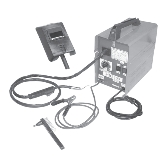
MIG-100 WELDER
MIG-100 WELDER
MIG-100 WELDER
MIG-100 WELDER
MIG-100 WELDER
WITH THERMAL OVERLOAD
WITH THERMAL OVERLOAD
WITH THERMAL OVERLOAD
WITH THERMAL OVERLOAD
WITH THERMAL OVERLOAD
Assembly AND OPERATING INSTRUCTIONS
Visit our Web site at http://www.harborfreight.com
©
Copyright
2004 by Harbor Freight Tools
manual or any artwork contained herein may be reproduced in any shape or
form without the express written consent of Harbor Freight Tools.
For technical questions and replacement parts, please call 1-800-444-3353.
3491 Mission Oaks Blvd., Camarillo, CA 93011
REVISED 12/04
91124
®
. All rights reserved. No portion of this
®
Advertisement
Table of Contents

Related Manuals for Chicago Electric MIG-100 91124


Summary of Contents for Chicago Electric MIG-100 91124
- Page 1 MIG-100 WELDER MIG-100 WELDER MIG-100 WELDER MIG-100 WELDER MIG-100 WELDER WITH THERMAL OVERLOAD WITH THERMAL OVERLOAD WITH THERMAL OVERLOAD WITH THERMAL OVERLOAD WITH THERMAL OVERLOAD ASSEMBLY AND OPERATING INSTRUCTIONS 3491 Mission Oaks Blvd., Camarillo, CA 93011 Visit our Web site at http://www.harborfreight.com ©...
-
Page 2: Specifications
Both settings: 10 min. shutdown, 3 min. back on with Light 0.030”; Spare: Welder Tip 0.035 inch; Will also accept 0.023” welder tip 0.030 inch flux core wire when using 0.030” Welder Tip 4 inches diameter 14-1/2 (L) x 8-1/2 (W) x 15-1/2 (H) inches 34.45 lbs. - Page 3 Use the right tool for the job. Do not attempt to force a small tool or attachment to do the work of a larger industrial tool. There are certain applications for which this tool was designed. Do not modify this tool and do not use this tool for a purpose for which it was not intended.
- Page 4 Protective clothing should be hole-free, dry, and ANSI approved. This unit draws enough current to cause serious injury or death. Before turning the welder on, check the electrode holder to be sure that there are no protruding screw heads, and that all insulation is secure.
- Page 5 Refer to the photo at the top of page 6, and the Assembly Drawing on page Attach the Cover Locking Spring (8) to the front of the Base Frame (14) using the supplied self-tapping screw. SKU 91124 Unpacking Power Cord (32) Wire Spool and Spare Welding Tip not shown here. Assembly Page 5 MIG-100 Welder...
- Page 6 10-minute period, during which a given welder can safely produce a particular welding current. For example, this 90 amp welder with a 10% duty cycle must be rested for at least 9 minutes after 1 minute of continuous welding.
- Page 7 Note: If too much current is drawn from the MIG Welder, the Thermal Overload protector will activate, the amber indicator will light, and the Arc Welder will turn off until it cools down. If this happens, turn the Power Switch to the OFF position and wait about 3 ~ 5 minutes.
- Page 8 Caution: Before performing any maintenance on the MIG Welder, unplug the Power Cord from the electrical outlet. Periodically remove the Right and Left side panels (12 and 13), and using compressed air, blow out all dust from the interior. Store in a clean and dry location.
- Page 9 If the wire does not feed, view the Wire Feed Unit and see if the wire is being pushed. If it is not, turn the welder OFF and add more tension to the Wire Feed Adjusting Spring (36). 14. Turn the welder ON again and press the Trigger.
- Page 10 Left Side Panel Base Frame Foot Washer Self-tapping Screw, ST4.2*13 Transformer Carriage Thermostat Transformer SKU 91124 Welder Parts List Item # Middle Partition Board Overload Indicator Lamp Wire Feed Unit Reel Spring Wing Nut, M6 Reel Locking Knob Wire Reel Reel Holder Self-tapping Screw, ST4.2*25...
- Page 11 Welder Assembly Drawing NOTE: Some parts are listed and shown for illustration purposes only and are not avail- able individually as replacement parts. SKU 91124 Page 11...
- Page 12 Welder Assembly Photographs SKU 91124 Page 12...
- Page 13 Wiring Schematic SKU 91124 Page 13...