Table of Contents
Advertisement
Quick Links
Advertisement
Table of Contents

Related Manuals for LAUMAS W200-MU


Summary of Contents for LAUMAS W200-MU
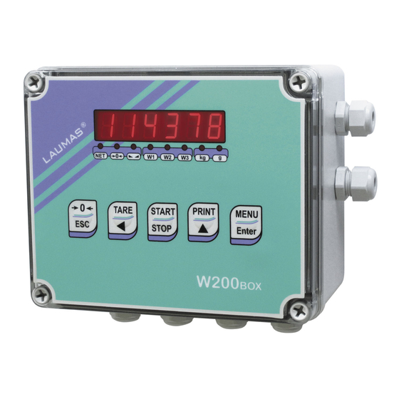
- Page 1 Microlectra bv. www.microlectra.nl info@microlectra.nl Installation and User Manual version 1.08 W200 Base 2014/30/EU EN55022:2010 EN61000-6-2:2005 EN61000-6-4:2007 SYSTEM IDENTIFICATION Microlectra bv. Augustapolder 12. 2992 SR Barendrecht. The Netherlands. www.microlectra.nl info@microlectra.nl...
- Page 2 No guarantee against misuse. Batteries: Laumas provides 1 year guarantee from the date of delivery note, against material defects or battery manufacturing faults. Disposal of Waste Equipment by Users in Private Households in the European Union This symbol on the product or on its packaging indicates that this product must not be disposed of with your other household waste.
-
Page 3: Table Of Contents
TABLE OF CONTENTS USER WARNINGS ......................... 1 RECOMMENDATIONS FOR CORRECT INSTALLATION OF WEIGHING INSTRUMENTS . 1 RECOMMENDATIONS FOR CORRECT INSTALLATION OF THE LOAD CELLS ....1 LOAD CELL INPUT TEST (QUICK ACCESS) ................. 3 LOAD CELL TESTING ......................3 MAIN SPECIFICATIONS OF THE INSTRUMENT..............4 BUFFER BATTERY ........................ - Page 4 RS485 SERIAL COMMUNICATION ....................27 DIRECT CONNECTION BETWEEN RS485 AND RS232 WITHOUT CONVERTER ....... 27 WEIGHT READING VIA SERIAL PORT ................28 WEIMOD MODE ..........................28 WEIRIP MODE ..........................29 RS485 CONNECTION ........................30 RS232 CONNECTION ........................30 TEST ............................31 DATE AND TIME SETTING ....................
-
Page 5: User Warnings
USER WARNINGS RECOMMENDATIONS FOR THE PROPER USE OF WEIGHING INSTRUMENT Keep away from heat sources and direct sunlight Repair the instrument from rain (except special IP versions) Do not wash with water jets (except special IP versions) Do not dip in water Do not spill liquid on the instrument Do not use solvents to clean the instrument Do not install in areas subject to explosion hazard (except special Atex versions) - Page 6 CONNECTING SEVERAL CELLS IN PARALLEL: Connect several cells in parallel by using - if necessary - a watertight junction box with terminal box. The cell connection extension cables must be shielded, led individually into their piping or conduit and laid as far as possible from the power cables (in case of 4-wire connections, use cables with 4x1 mm minimum cross-section).
-
Page 7: Load Cell Input Test (Quick Access)
LOAD CELL INPUT TEST (QUICK ACCESS) From the weight display, press for 3 seconds; the response signal of the load cells is displayed, expressed in mV with four decimals. LOAD CELL TESTING Load cell resistance measurement (use a digital multimeter): - Disconnect the load cells from the instrument and check that there is no moisture in the cell junction box caused by condensation or water infiltration. -
Page 8: Main Specifications Of The Instrument
Two serial ports (RS485 and RS232) for connection to: PC/PLC up to 32 instruments (max 99 with line repeaters) by ASCII Laumas or ModBus R.T.U. protocol, remote display, printer. Optional: integrated Profibus DP, DeviceNet, CANopen, Profinet IO, Ethernet/IP, Ethernet TCP/IP, Modbus/TCP output. -
Page 9: Technical Specifications
TECHNICAL SPECIFICATIONS POWER SUPPLY and CONSUMPTION (VDC) 12/24 VDC ±10%; 5 W (standard) POWER SUPPLY and CONSUMPTION (VAC) 115/230 VAC (optional); 50-60 Hz; 6 VA NO. OF LOAD CELLS IN PARALLEL and SUPPLY max 8 (350 ohm); 5 VDC / 120 mA LINEARITY / ANALOG OUTPUT LINEARITY <... -
Page 10: Electrical Connections
ELECTRICAL CONNECTIONS TERMINALS LEGEND +SUPPLY (12/24 VDC) OUTPUT No. 5 otherwise: 115/230 VAC optional version: +ANALOG OUTPUT (0÷10 V) +OUTPUT (24 VDC) -SUPPLY (12/24 VDC) RS232, RS485: SHIELD, GND E/EC OPTION: GND E/EC OPTION otherwise: 115/230 VAC optional version: -ANALOG OUTPUT COMMON -OUTPUT (24 VDC) RS232, RS485: SHIELD, GND E/EC OPTION: GND... -
Page 11: Wiring Diagram
WIRING DIAGRAM OUTPUTS INPUTS (1) ANALOG OUTPUT E OPTION 12/24 VDC max 115 VAC supply OPTION supply 150 mA 5÷24 VDC 14 15 4 5 6 7 9 10 RS232 Buttons not included in the supply EC OPTION to instrument 2 3 4 5 6 Current output: max load 300 ohm... -
Page 12: Led And Key Function
LED AND KEY FUNCTION Main function Secondary function * net weight (semi-automatic tare or preset tare) LED lit: input 1 closed zero (deviation from zero not more than ±0.25 divisions) LED lit: input 2 closed stability LED lit: input 3 closed unit of measure: kg LED lit: output 4 closed unit of measure: g... -
Page 13: Menu Map
MENU MAP Into menus changes are applied right after pressing the ENTER key ( no further confirmation is required). SETPOINT … … … SYSTEM PARAMETERS ... - Page 14 optional optional - 10 -...
-
Page 15: Instrument Commissioning
INSTRUMENT COMMISSIONING Upon switch-on, the display shows in sequence: - → (ONLY in case of approved program); - instrument model (e.g.: ); - followed by the software code (e.g.: ); - program type: (base); - followed by the software version (e.g.: ); - ... -
Page 16: Programming Of System Parameters
PROGRAMMING OF SYSTEM PARAMETERS From the weight display, press simultaneously keys MENU and ESC to access the parameter setting. MENU/ENTER: to enter a menu/confirm the data entry. to modify the displayed figure or menu item. to select a new figure or modify the displayed menu item. ESC: to cancel and return to the previous menu. -
Page 17: Maximum Capacity
MAXIMUM CAPACITY : maximum displayable weight (from 0 to max full scale; default: 0). When the weight exceeds this value by 9 divisions, the display shows . To disable this function, set 0. TARE WEIGHT ZERO SETTING ... -
Page 18: Real Calibration (With Sample Weights)
REAL CALIBRATION (WITH SAMPLE WEIGHTS) After having performed the THEORETICAL CALIBRATION and TARE WEIGHT ZERO SETTING, this function allows correct calibration to be done using sample weights of known value and, if necessary, any deviations of the indicated value from the correct value to be corrected. -
Page 19: Filter On The Weight
FILTER ON THE WEIGHT Setting this parameter allows a stable weight display to be obtained. To increase the effect (weight more stable) increase the value (from 0 to 9, default 4). As seen in the diagram: - By confirming the message, the currently programmed filter value is displayed. - By changing and confirming the value, the weight is displayed and it will be possible to experimentally verify its stability. -
Page 20: Zero Parameters
ZERO PARAMETERS RESETTABLE WEIGHT SETTING FOR SMALL WEIGHT CHANGES (from 0 to max full scale; default: 300; considered decimals: 300 – 30.0 – 3.00 – 0.300): this parameter indicates the maximum weight value resettable by external contact, keypad or serial protocol. -
Page 21: Setting Units Of Measure
SETTING UNITS OF MEASURE These are the available units of measure: kilograms : grams : tons : pounds* : : newtons* litres* : bars* : atmospheres* : pieces* : newton metres* : : kilogram metres* other generic units of measure not included in the list* : If the print function is enabled, the symbol corresponding to the selected unit of measure will be printed after the measured value. -
Page 22: Net Functions
: pieces, in set the weight of one piece; : newton metres, the value set in will be multiplied by the weight value currently displayed; : kilogram metres, the value set in will be multiplied by the weight value currently displayed;... -
Page 23: Outputs And Inputs Configuration
OUTPUTS AND INPUTS CONFIGURATION … … OUTPUTS The outputs are set by default as follows: / / / / . Possible operation modes: - (normally open): the relay is de-energised and the contact is open when the weight is lower than the programmed setpoint value;... -
Page 24: Limit Mode
INPUTS Default: input 1 = input 2 = input 3 = Possible operation modes: - (NET/GROSS): by closing this input for no more than one second, it’s making an operation of SEMI-AUTOMATIC TARE and the display will show the net weight. To display the gross weight again, hold the NET/GROSS input closed for 3 seconds. -
Page 25: Semi-Automatic Tare (Net/Gross)
SEMI-AUTOMATIC TARE (NET/GROSS) THE SEMI-AUTOMATIC TARE OPERATION IS LOST UPON INSTRUMENT POWER- OFF. To perform a net operation (SEMI-AUTOMATIC TARE), close the NET/GROSS input or press the TARE key for less than 3 seconds. The instrument displays the net weight (just set to zero) and the NET LED lights up. -
Page 26: Preset Tare (Subtractive Tare Device)
PRESET TARE (SUBTRACTIVE TARE DEVICE) It is possible to manually set a preset tare value to be subtracted from the display value provided that the ≤ max capacity condition is verified. By default the instrument shows the last programmed preset tare value: to apply it press then ENTER. -
Page 27: Peak
PEAK : the peak function is run only via input (default); : the peak function is also run via the START/STOP key. By keeping the PEAK input closed or pressing the START/STOP key (if enabled), the maximum weight value reached remains displayed. By opening the input or keeping the START/STOP key (if enabled) pressed for 3 seconds, the current weight is displayed. - Page 28 - : set the weight value for which you wish to obtain the maximum analog output value; it must correspond to the value set in the PLC program (default: calibration full scale). E.g.: if I am using a 4÷20 mA output and in the PLC program I wish to have 20 mA = 8000 kg, I will set the parameter to 8000.
-
Page 29: Serial Communication Setting
SERIAL COMMUNICATION SETTING - / : communication port. - : it disables any type of communication (default). - : MODBUS-RTU protocol; possible addresses: from 1 to 99 (see Communication protocols manual). - : ASCII bidirectional protocol; possible addresses: from 1 to 99 (see Communication protocols manual). - Page 30 - : maximum transmission frequency (10 – 20 – 30 – 40 – 50 – 60 – 70 – 80 – 100 – 200 – 300; default: 10); o be set when the transmission protocol is selected. Maximum setting frequency (): - 20 Hz with minimum baud rate 2400 baud.
-
Page 31: Rs232 Serial Communication
RS232 SERIAL COMMUNICATION INSTRUMENT RS232 TXD RS232 RXD DB9-F RS485 SERIAL COMMUNICATION INSTRUMENT INSTRUMENT INSTRUMENT max 500 m 24 VDC RS485 + RS485 + RS485 - RS485 - CONVLAU If the RS485 network exceeds 100 metres in length or baud-rate over 9600 are used, two terminating resistors are needed at the ends of the network. -
Page 32: Weight Reading Via Serial Port
WEIGHT READING VIA SERIAL PORT Overview: By transmitting instrument, it means the one connected to the load cell. By receiving instrument, it means the one which receives the weight via serial port. This function allows the instrument to read the weight by another instrument (transmitting instrument) rather than by a load cell, via the RS485 or RS232 serial port. -
Page 33: Weirip Mode
- : even parity - : odd parity - : stop bit (1 – 2; default: 1) The transmitting instrument display is locked and shows the instrument model. To unlock it, disconnect the receiving instrument and follow the procedure in section KEYPAD OR DISPLAY LOCKING in the transmitting instrument manual. -
Page 34: Rs485 Connection
RS485 CONNECTION Transmitting instrument Receiving instrument INSTRUMENT Connector Signal RS485: - W200 TERMINAL RS485: + W200BOX RS485: SHIELD, GND If the RS485 network exceeds 100 metres in length or baud-rate is higher than 9600, two terminating resistors are needed at the ends of the network. Two 120 ohm resistors are to be connected, between the “+”... -
Page 35: Test
TEST - Input Test: : ensure that for each open input is displayed, is displayed when the input is closed. - Output Test: : setting ensure that the corresponding output opens. Setting ensure that the corresponding output closes. -
Page 36: Setpoint Programming
SETPOINT PROGRAMMING From the weight display, press MENU to access the setpoint setting. MENU/ENTER: to enter a menu/confirm the data entry. to modify the displayed figure or menu item. to select a new figure or modify the displayed menu item. ESC: to cancel and return to the previous menu. - Page 37 : maximum displayable value exceeded on transmitting instrument (value higher than 999999 or lower than -999999). : weight too high: zero setting not possible. : this message appears in the sample weight setting, in real calibration, after the fifth sample weight value has been entered. the value set for the parameter is beyond the permitted values;...
-
Page 38: Printing Examples
PRINTING EXAMPLES If the printer has been set (see section SERIAL COMMUNICATION SETTINGS), from the weight display press the PRINT key: BASIC PRINTOUT ::::::::::::::::::::::: W200 BASE Addr:01 DATE: 12/09/11 14:48:12 GROSS 878 kg 589 kg TARE 289 kg BASIC PRINTOUT (PEAK ENABLED): ::::::::::::::::::::::: W200 BASE... -
Page 39: Reserved For The Installer
RESERVED FOR THE INSTALLER MENU LOCKING Through this procedure, it’s possible to block the access to any menu on the instrument. Select the menu that you wish to lock: press ESC and simultaneously for 3 seconds, the display shows ... - Page 40 Upon instrument power-on hold down the ESC key until the display shows , then proceed as follows: CONSTANTS RESTORE (does not erase the calibration): confirm , use arrow keys to select , set code 6935 and confirm. PROGRAM SELECTION: confirm and use the arrow keys to select the desired program: : basic program, setpoint management only.
-
Page 41: Keypad Or Display Locking
KEYPAD OR DISPLAY LOCKING Press ESC immediately followed by hold them down for about 5 seconds (this operation is also possible via the MODBUS and ASCII protocols): - : no lock. - : keypad lock: if active, when a key is pressed the message is displayed for 3 seconds. -
Page 42: Declaration Of Conformity - Eu
CERTIFICAZIONE DEL SISTEMA DI GARANZIA DELLA QUALITÀ DELLA PRODUZIONE email: laumas@laumas.it web: http://www.laumas.com LAUMAS Elettronica S.r.l. Tel. (+39) 0521 683124 - Fax (+39) 0521 681091 Fabbricante metrico Prot. N. 7340 Parma - R.E.A. PR N. 169833 - Reg. Imprese Via 1° Maggio 6 – 43022 Montechiarugolo (PR) Italy PR N.19393 - Registro Nazionale Pile N°...