
Related Manuals for LAUMAS TLU


Summary of Contents for LAUMAS TLU
- Page 1 ENGLISH ENGLISH ENGLISH ENGLISH Installation and User Manual version 1.04 TLU - TLUANA 2014/30/EU EN55022:2010 EN61000-6-2:2005 EN61000-6-4:2007 SYSTEM IDENTIFICATION...
-
Page 2: Further Information
No guarantee against misuse. Batteries: Laumas provides 1 year guarantee from the date of delivery note, against material defects or battery manufacturing faults. Disposal of Waste Equipment by Users in Private Households in the European Union This symbol on the product or on its packaging indicates that this product must not be disposed of with your other household waste. -
Page 3: Table Of Contents
TABLE OF CONTENTS USER WARNINGS ........................1 RECOMMENDATIONS FOR CORRECT INSTALLATION OF WEIGHING INSTRUMENTS . 1 RECOMMENDATIONS FOR CORRECT INSTALLATION OF THE LOAD CELLS ....1 LOAD CELL INPUT TEST (QUICK ACCESS) ................3 LOAD CELL TESTING ....................... 3 ... - Page 4 ASCII BIDIRECTIONAL PROTOCOL ..................23 SETPOINT PROGRAMMING ..................23 1.1. SETTING SETPOINT VALUES CURRENTLY IN USE ............23 1.2. SETPOINT STORAGE IN EEPROM MEMORY ..............23 READING WEIGHT, SETPOINT AND PEAK (IF PRESENT) FROM PC ....... 24 ...
-
Page 5: User Warnings
USER WARNINGS RECOMMENDATIONS FOR THE PROPER USE OF WEIGHING INSTRUMENT Keep away from heat sources and direct sunlight Repair the instrument from rain (except special IP versions) Do not wash with water jets (except special IP versions) Do not dip in water Do not spill liquid on the instrument Do not use solvents to clean the instrument Do not install in areas subject to explosion hazard (except special Atex versions) - Page 6 CONNECTING SEVERAL CELLS IN PARALLEL: Connect several cells in parallel by using - if necessary - a watertight junction box with terminal box. The cell connection extension cables must be shielded, led individually into their piping or conduit and laid as far as possible from the power cables (in case of 4-wire connections, use cables with 4x1 mm minimum cross-section).
-
Page 7: Load Cell Input Test (Quick Access)
LOAD CELL INPUT TEST (QUICK ACCESS) From the weight display, press ▲ for 3 seconds; the response signal of the load cells is displayed, expressed in mV with four decimals. LOAD CELL TESTING Load cell resistance measurement (use a digital multimeter): - Disconnect the load cells from the instrument and check that there is no moisture in the cell junction box caused by condensation or water infiltration. -
Page 8: Main Specifications Of The Instrument
MAIN SPECIFICATIONS OF THE INSTRUMENT Weight indicator and transmitter for Omega/DIN rail mounting suitable for back panel or junction box. Six-digit semi-alphanumeric display (8mm h), 7 segment. Four-key keyboard. Dimensions: 25x115x120 mm. IP67 box version (170x140x95mm). Four fixing holes diameter 4 mm (centre distance 122x152 mm). Displays the gross weight;... -
Page 9: Technical Specifications
TECHNICAL SPECIFICATIONS POWER SUPPLY and CONSUMPTION (VDC) 12/24 VDC (standard) ±10%; 5 W NO. OF LOAD CELLS IN PARALLEL and SUPPLY max 8 (350 ohm); 5 VDC / 120 mA LINEARITY / ANALOG OUTPUT LINEARITY < 0.01% F.S.; < 0.01% F.S. THERMAL DRIFT / ANALOG OUTPUT THERMAL <... -
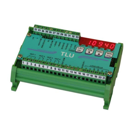
Page 10: Electrical Connections
ELECTRICAL CONNECTIONS BASIC INFORMATION - It is recommended that the power supply negative pole be grounded. - It is possible to supply up to eight 350 ohm load cells or sixteen 700 ohm load cells. - For 4-wire load cells, make a jumper between EX- and REF- and between EX+ and REF+. - Connect terminal 0 VDC”... -
Page 11: Led And Key Function
LED AND KEY FUNCTION Main function Secondary function * net weight LED: net weight display (semi- LED lit: input 1 closed automatic tare or preset tare) zero LED (deviation from zero not more than +/- LED lit: input 2 closed 0.25 divisions) stability LED LED lit: output 1 closed... -
Page 12: Menu Map
MENU MAP Into menus changes are applied right after pressing the ENTER key ( no further confirmation is required). SETPOINT SYSTEM PARAMETERS TLUANA ... -
Page 13: Instrument Commissioning
INSTRUMENT COMMISSIONING Upon switch-on, the display shows in sequence: - instrument model (e.g.: ); - followed by the software code (e.g.: ); - program type: (base); - followed by the software version (e.g.: ); - followed by the hardware code (e.g.: ); - serial number (e.g.: );... -
Page 14: Programming Of System Parameters
PROGRAMMING OF SYSTEM PARAMETERS From the weight display, press simultaneously keys MENU and ESC to access the parameter setting. MENU/ENTER: to enter a menu/confirm the data entry. ▲: to modify the displayed figure or menu item. ◄: to select a new figure or modify the displayed menu item. ESC: to cancel and return to the previous menu. -
Page 15: Maximum Capacity
MAXIMUM CAPACITY : Maximum displayable weight (from 0 to max full scale; default: 0). When the weight exceeds this value by 9 divisions, the display shows . To disable this function, set 0. TARE WEIGHT ZERO SETTING This menu may also be accessed directly from the weight display, holding down the key for 3 seconds. -
Page 16: Real Calibration (With Sample Weights)
REAL CALIBRATION (WITH SAMPLE WEIGHTS) After having performed the THEORETICAL CALIBRATION and TARE WEIGHT ZERO SETTING, this function allows correct calibration to be done using sample weights of known value and, if necessary, any deviations of the indicated value from the correct value to be corrected. -
Page 17: Filter On The Weight
FILTER ON THE WEIGHT Setting this parameter allows a stable weight display to be obtained. To increase the effect (weight more stable) increase the value (from 0 to 9, default 4). As seen in the diagram: - By confirming the message, the currently programmed filter value is displayed. - By changing and confirming the value, the weight is displayed and it will be possible to experimentally verify its stability. -
Page 18: Automatic Zero Setting At Power-On
AUTOMATIC ZERO SETTING AT POWER-ON (from 0 to max 20% of full scale; default: 0): If at switch-on the weight value is lower than the value set in this parameter and does not exceed the value, the weight is reset. To disable this function, set 0. -
Page 19: Preset Tare (Subtractive Tare Device)
While the net weight is displayed, keep ▲ pressed to display gross weight. When the key is released the net weight will be displayed again. The semi-automatic tare operation is not allowed if the gross weight is zero. PRESET TARE (SUBTRACTIVE TARE DEVICE) It is possible to manually set a preset tare value to be subtracted from the display value provided that the ... -
Page 20: Analog Output (Tluana)
ANALOG OUTPUT (TLUANA) - : it selects the analog output type (4÷20 mA, 0÷20 mA, 0÷10 V, 0÷5 V, ±10 V, ±5 V; default: 4÷20 mA). for the output ±10 V and ±5 V the soldered jumper SW1 must be closed: ▫... -
Page 21: Serial Communication Setting
For example: = 10000 = 0 analog output 0÷10 V Weight = 0 kg analog output = 10 V Weight = 5000 kg analog output = Weight =10000 kg analog output = SERIAL COMMUNICATION SETTING - / : communication port. - : it disables any type of communication (default). -
Page 22: Rs232 Serial Communication
RS232 SERIAL COMMUNICATION DB9-F RS485 SERIAL COMMUNICATION RS485 termination 28 29 28 29 28 29 J2 J1 max 500 m 24 Vcc RS485 + RS485 + RS485 - RS485 - CONVLAU If the RS485 network exceeds 100 metres in length or baud-rate over 9600 are used, close the two jumpers, called "RS-485 termination", to activate two 120 ohm terminating resistors between the ‘+’... -
Page 23: Direct Connection Between Rs485 And Rs232 Without Converter
DIRECT CONNECTION BETWEEN RS485 AND RS232 WITHOUT CONVERTER Since a two-wire RS485 output may be used directly on the RS-232 input of a PC or remote display, it is possible to implement instrument connection to an RS-232 port in the following manner: INSTRUMENT RS232 RS485 –... -
Page 24: Setpoint Programming
SETPOINT PROGRAMMING From the weight display, press MENU to access the setpoint setting. MENU/ENTER: to enter a menu/confirm the data entry. ▲: to modify the displayed figure or menu item. ◄: to select a new figure or modify the displayed menu item. ESC: to cancel and return to the previous menu. -
Page 25: Alarms
ALARMS the load cell is not connected or is incorrectly connected; the load cell signal exceeds : 39 mV; the conversion electronics (AD converter) is malfunctioning; the load cell is a 4- wire and there are no jumpers between EX- and REF- and between EX+ and REF+. the weight display exceeds 110% of the full scale. -
Page 26: Continuous Weight Transmission To Remote Displays Protocol
CONTINUOUS WEIGHT TRANSMISSION TO REMOTE DISPLAYS PROTOCOL This protocol allows the continuous weight transmission to remote displays. The communication string is transmitted 10 times per second. Following communication modes availables (see SERIAL COMMUNICATION SETTINGS section): - : communication with RIP5/20/60, RIP50SHA, RIPLED series remote displays; the remote display shows the net weight or gross weight according to its settings. -
Page 27: Ascii Bidirectional Protocol
ASCII BIDIRECTIONAL PROTOCOL The instrument replies to the requests sent from a PC/PLC. It is possible to set a waiting time for the instrument before it transmits a response (see parameter in the SERIAL COMMUNICATION SETTINGS section). Following communication modes availables (see SERIAL COMMUNICATION SETTINGS section in instrument manual): Captions: $: Beginning of a request string (36 ASCII);... -
Page 28: Reading Weight, Setpoint And Peak (If Present) From Pc
- incorrect reception: &&aa?\ckckCR READING WEIGHT, SETPOINT AND PEAK (IF PRESENT) FROM PC The PC transmits the following ASCII string: $aajckckCR where: j = a to read setpoint 1 j = b to read setpoint 2 j = c to read setpoint 3 j = d to read setpoint 4 j = t to read gross weight j = n to read net weight... -
Page 29: Commutation Of Gross Weight To Net Weight
COMMUTATION OF GROSS WEIGHT TO NET WEIGHT The PC transmits the following ASCII string: $aaNETckckCR Possible instrument responses: - correct reception: &&aa!\ckckCR - incorrect reception: &&aa?\ckckCR COMMUTATION OF NET WEIGHT TO GROSS WEIGHT The PC transmits the following ASCII string: $aaGROSSckckCR Possible instrument responses: - correct reception: &&aa!\ckckCR - incorrect reception: &&aa?\ckckCR... -
Page 30: Real Calibration (With Sample Weight)
where: xxxxxx = 6 characters to indicate the required weight value; t = 1 character to indicate the weight (116 ASCII). Example: Zeroing the weight of the instrument with address 2: For the calibration you have to make sure that the system is unloaded or that the instrument measures a signal equal to the mV in the same situation: query: $02z78(Cr) response: &02000000t\76(Cr) -
Page 31: Keypad Lock (Block The Access To The Instrument)
KEYPAD LOCK (BLOCK THE ACCESS TO THE INSTRUMENT) The PC transmits the following ASCII string: $aaKEYckckCR Possible instrument responses: - correct reception: &&aa!\ckckCR - incorrect reception: &&aa?\ckckCR 10. KEYPAD UNLOCK The PC transmits the following ASCII string: $aaFREckckCR Possible instrument responses: - correct reception: &&aa!\ckckCR - incorrect reception: &&aa?\ckckCR 11. -
Page 32: Modbus-Rtu Protocol
MODBUS-RTU PROTOCOL INTRODUCTION The MODBUS-RTU protocol allows the management of the reading and writing of the following registries according to the specifications found on the reference document for this Modicon PI- MBUS-300 standard. To select the MODBUS-RTU communication see SERIAL COMMUNICATION SETTINGS section in instrument manual. -
Page 33: Communication Error Management
DELAY parameter in the settings menu for the serial connections, allows the instrument to respond with a further delay and this directly influences the number of interrogations possible in the unit of time. For additional information on this protocol refer to the general technical specifications PI_MBUS_300. -
Page 34: List Of Available Registers
a time-out for reception of the answer. If it does not receive an answer it deduces that there has been a communication error. In the case of the string received correctly but not executable, the slave responds with an EXCEPTIONAL RESPONSE. The "FUNCTION" field is transmitted with the MSB at 1. EXCEPTIONAL RESPONSE Address Function... -
Page 35: Real Calibration (With Sample Weights)
40020 SETPOINT 2 L “Command Register” 40021 SETPOINT 3 H 40022 SETPOINT 3 L 40023 SETPOINT 4 H 40024 SETPOINT 4 L 40025 DELAY 1 H 40026 DELAY 1 L 40027 DELAY 2 H 40028 DELAY 2 L 40029 DELAY 3 H 40030 DELAY 3 L 40031... -
Page 36: Inputs And Outputs Registers
weight in the registers “weight value corresponding to ZERO of the analog output H” (40043) and “weight value corresponding to ZERO of the analog output L” (40044). After writing the value, send the command 99 from the “Command Register” to save it in EEPROM memory. STATUS REGISTER (40007) Bit 0 Cell Error... -
Page 37: Division And Units Of Measure Register (40014)
DIVISION AND UNITS OF MEASURE REGISTER (40014) This register contains the current setting of the divisions (parameter ) and of the units of measure (parameter ). H Byte L Byte unit of measure division Use this register together with the Coefficient registers to calculate the value displayed by the instrument. -
Page 38: Command Register (40006)
COMMAND REGISTER (40006) No command Reserved Reserved Keypad lock Keypad and display unlock Keypad and display lock NET display (see section SEMI- AUTOMATIC TARE (NET/GROSS)) SEMI-AUTOMATIC ZERO Save data in EEPROM GROSS display Zero-setting for calibration (see section SEMI- (see section TARE WEIGHT ZERO SETTING) AUTOMATIC TARE (NET/GROSS)) Reserved... -
Page 39: Communication Examples
COMMUNICATION EXAMPLES The numerical data below are expressed in hexadecimal notation with prefix h. EXAMPLE 1 Command for multiple writing of registers (hexadecimal command 16, h10): Assuming that we wish to write the value 0 to the register 40017 and the value 2000 to the register 40018, the string to generate must be: h01 h10 h00 h10 h00 h02 h04 h00 h00 h07 hD0 hF1 h0F The instrument will respond with the string:... - Page 40 Number of registers L Number of registers L Byte Count CRC16 H Datum 1 H CRC16 L Datum 1 L Datum 2 H Datum 2 L Datum 3 H Datum 3 L Datum 4 H Datum 4 L CRC16 H CRC16 L EXAMPLE 3 Multiple commands reading for registers (hexadecimal command 3, h03):...
-
Page 41: Reserved For The Installer
RESERVED FOR THE INSTALLER MENU LOCKING Through this procedure, it’s possible to block the access to any menu on the instrument. Select the menu that you wish to lock: press ESC ◄ ▲ simultaneously for 3 seconds, the display shows (the left point on the text indicates that this menu item is now locked). -
Page 42: Keypad Or Display Locking
PROGRAM SELECTION: confirm and use the arrow keys to select the desired program: : basic program, setpoint management only. : to be used when the loaded weighing system correspond to not loaded cells and vice versa (product increases while weight on load cells actually decreases). By confirming, the instrument is restored to default and data is erased. -
Page 43: Declaration Of Conformity - Eu
Niniejszym oświadczamy, że produkt, którego niniejsze oświadczenie dotyczy, jest zgodny z Deklaracja zgodności poniższymi normami. Заявление о Мы заявляем, что продукт, к которому относится данная декларация, соответствует соответствии перечисленным ниже нормам. Models: TLU - TLUANA Mark Applied EU Directive Standards 2014/35/EU Not Applicable (N/A) for VDC type Low Voltage Directive...