HHB PORTADRIVE PDR2000 Quick Start Manual
Hhb pdr2000 recorders: quick start
Hide thumbs
Also See for PORTADRIVE PDR2000:
- Brochure & specs (2 pages) ,
- Operation manual (112 pages) ,
- Operation manual (135 pages)
Advertisement
Quick Links
Download this manual
See also:
Operating Manual
HHB PORTADRIVE: QUICK START GUIDE - draft
1. Connect a power source
Plug the 4-pin XLR of the supplied AC Adapter into the DC INPUT socket on the left side
panel, or
Insert the supplied NP-L50 Lithium Ion battery (shipped discharged) into the battery
compartment and turn the thumbwheel on the compartment door clockwise to lock in place.
Tip – we recommend that a charged NP-L50 battery is always fitted even when powering from
an external supply. This ensures that in the event of an external power failure, PORTADRIVE
will seamlessly switch to being powered from the internal NP-L50 battery.
Note - It is possible to charge the supplied IDX NP-L50 battery inside PORTADRIVE. To do this,
you must power PORTADRIVE using the supplied AC adapter. To start charging, power on
PORTADRIVE, access the top panel SETUP menu, and then select PWR using the F3 function
key. Cursor to the 'Power Mode' box (accessible only if PORTADRIVE is powered by the AC
adaptor) and use the data wheel to change the mode from ANALOG AUDIO to BATTERY
CHARGER. A complete charge cycle takes about 8 hours. Charging is not possible with
PORTADRIVE turned off.
2. Insert an HDD caddy
Insert the REMOVABLE HDD CADDY into the caddy compartment on the left hand side
panel pushing firmly home, then turn the caddy thumbwheel fully 90 degrees clockwise.
Note – If the HDD caddy is inserted after boot-up, it is necessary to mount it using SCAN (F3) in
the top panel DISK menu.
3. Power ON PORTADRIVE
Press the POWER SWITCH located on the top panel.
Tip – During transit, set the TOP PANEL ON/OFF switch located on the top panel to the OFF
position (opposite direction to the silk-screen arrow) to prevent the POWER SWITCH from
accidentally powering ON PORTADRIVE and inadvertently discharging the internal battery.
4. Using the front panel MODE keys (INPUT, BUSMIX, TRACK, OUTPUT) and
rotary encoders 1- 6.
Pressing a MODE key simultaneously selects the metering signals and the associated front
panel LCD menu.
For example, pressing the INPUT MODE key will switch the metering to monitor the eight
INPUT signals and switch the LCD to display the last accessed page from the INPUT menu.
Pressing a MODE key again and again will cycle though the various pages of the associated
menu.
The top row of the current front LCD menu shows a description of the parameters that can
be adjusted using the rotary encoders directly below. The bottom row shows the current
setting/value of the associated parameter and most of these parameters can be adjusted by
rotating the corresponding rotary encoder directly below the displayed setting/value.
5. Using the top panel MODE keys and FUNCTION keys (F1-F6)
Pressing a MODE key selects the associated top panel LCD menu.
The button graphics in the bottom row of the LCD screen describe the page that will be
selected by pressing the corresponding FUNCTION key (F1-F6) directly below each graphic.
1
Advertisement

Related Manuals for HHB PORTADRIVE PDR2000


Summary of Contents for HHB PORTADRIVE PDR2000
- Page 1 HHB PORTADRIVE: QUICK START GUIDE - draft 1. Connect a power source Plug the 4-pin XLR of the supplied AC Adapter into the DC INPUT socket on the left side panel, or Insert the supplied NP-L50 Lithium Ion battery (shipped discharged) into the battery compartment and turn the thumbwheel on the compartment door clockwise to lock in place.
-
Page 2: Template Options
6. Create a new session Think of a session as a container for all your recorded audio and its associated metadata. It is therefore necessary to create a session before recording can take place. a) Firstly, ensure the disk to be recorded to is formatted. This can be format FAT32 (BWF/AES31) or in Portadrive OS >V1.2, HFS (SDII/PROTOOLS V5). -
Page 3: Start Recording
YOU ARE NOW READY FOR RECORDING! Note – If you forget to create a session, PORTADRIVE will automatically create a default session called ‘SESSION 1’ for you so that you can start recording straight away. Obviously you should be aware that this default session may not be set up correctly for your application, but at least something will be recorded. - Page 4 Pressing F6 twice will open the selected session. 15. Power OFF PORTADRIVE Press the POWER button located on the top panel. At the ‘Power down unit?’ prompt, press YES (F5/F6). PORTADRIVE will shutdown within a few seconds. PDR2000 SIMPLE SIGNAL BLOCK DIAGRAM ANALOG LINE AMP MIC AMP INPUTS 1 - 6 &...
-
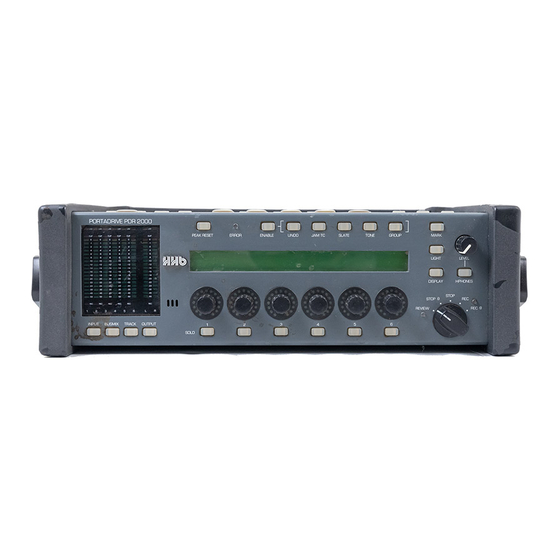
Page 5: Pdr2000 Front Panel
PDR2000 FRONT PANEL PEAK METERS RESET SOLO KEYS MODE KEYS PDR2000 TOP PANEL MODE KEYS SPEAKER POWER TOP PANEL SWITCH ON/OFF UTILITY ERROR KEYS MULTI-PURPOSE ENCODERS 320x240 LCD & CURSOR FUNCTION KEYS KEYS TRANSPORT LOCATE LIGHT PROGRAMMABLE KEYS ENTER KEY... -
Page 6: Left Panel
LEFT PANEL BATTERY PS2 KEYBOARD COMPARTMENT INPUT DC INPUT REMOVABLE PARALLEL REMOTE HDD CADDY CONNECTION ETHERNET SCSI RS422...