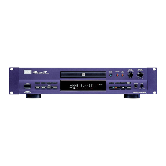
HHB BurnIT CDR-830 Service Manual
Professional
Hide thumbs
Also See for BurnIT CDR-830:
- Operating instructions manual (50 pages) ,
- Quick reference manual (2 pages) ,
- Technical bulletin (1 page)
Table of Contents
Advertisement
Quick Links
SCROLL
DISPLAY
MONITOR
TITLE/MODE
TRACK NO.
WRITE
AUTO
INPUT
ERASE
FINALIZE
MANUAL
SELECTOR
CD TEXT
THIS MANUAL IS APPLICABLE TO THE
FOLLOWING MODEL(S) AND TYPE(S).
Model
Type
Power Requirement
CDR-830
KUXJ/CA
WYXJ
FOR U.S. MODELS
NECESSARY INFORMATION FOR DHHS
RULES MARKED ON THE REAR BASE AND ON
THE TOP OF CD MECHANISM AS BELOW.
DANGER – LASER RADIATION WHEN OPEN.
AVOID DIRECT EXPOSURE TO BEAM.
CDR-830
DIGITAL
ANALOG
REC LEVEL
REC LEVEL
MENU/
TEXT
DELETE
SYNCHRO
PROFESSIONAL
Remarks
AC120V
AC220-240V
Advertisement
Table of Contents

Related Manuals for HHB BurnIT CDR-830


Summary of Contents for HHB BurnIT CDR-830
- Page 1 CDR-830 DIGITAL ANALOG REC LEVEL REC LEVEL MENU/ SCROLL DISPLAY MONITOR TITLE/MODE TEXT DELETE TRACK NO. WRITE AUTO INPUT ERASE FINALIZE SYNCHRO MANUAL SELECTOR PROFESSIONAL CD TEXT THIS MANUAL IS APPLICABLE TO THE FOLLOWING MODEL(S) AND TYPE(S). Model Type Power Requirement Remarks CDR-830 KUXJ/CA...
-
Page 2: Safety Information
The use of a substitute replacement component which does Leakage 0.5mA current Device not have the same safety characteristics as the HHB tester under recommended replacement one, shown in the parts list in test this Service Manual, may create shock, fire, or other hazards. -
Page 3: Table Of Contents
1. Laser Interlock Mechanism IMPORTANT The position of the switch (S101) on the LOAB Assy for THIS HHB APPARATUS CONTAINS LASER OF CLASS 3 b. detecting loading state is detected by the system microprocessor, and the design prevents laser diode... -
Page 4: Exploded Views And Parts List
CDR-830 2. EXPLODED VIEWS AND PARTS LIST • NOTES: Parts marked by "NSP" are generally unavailable because they are not in our Master Spare Parts List. • mark found on some component parts indicates the importance of the safety factor of the part. Therefore, when replacing, be sure to use parts of identical designation. - Page 5 CDR-830 (1) PACKING PARTS LIST Mark No. Description Part No. AC Power Cord See Contrast table (2) Registration Card See Contrast table (2) Audio Cable (L= 1m) RDE1036 CD-R Disc PEX1013 Burnlt Brochure PEX1014 Operating Instructions PRB1312 (English) Bar Code Label See Contrast table (2) Quick Start Guide PEX1017...
- Page 6 CDR-830 2.2 EXTERIOR SECTION KUXJ/CA type only Refer to "2.4 CD-R CORE ASSY(1/2)", "2.5 CD-R CORE ASSY(2/2)". KUXJ/CA Type Only NOTE Refer to " 2.3 FRONT PANEL ASSY " NOTE This Parts of no service part. partially of the PCB board of COMPLEX Assy.
- Page 7 CDR-830 (1) EXTERIOR SECTION PARTS LIST Mark No. Description Part No. Mark No. Description Part No. AUDIO ASSY See Contrast table (2) Screw BBZ30P080FCC AC Inlet PKP1012 Screw BBZ40P080FCC 25P Flexible Cable/30v PDD1220 Screw BBZ40P160FZK 9P Flexible Cable/60v PDD1221 Binder ZCA-T18S Connector Ass'y (8p) PDE1311...
- Page 8 CDR-830 2.3 FRONT PANEL SECTION Accessories of VR Assy. (1) FRONT PANEL SECTION PARTS LIST Mark No. Description Part No. Mark No. Description Part No. OPERATING ASSY See Contrast table (2) Rec Button 830 PAC2032 HEADPHONE ASSY See Contrast table (2) •...
- Page 9 CDR-830 2.4 CD-R CORE ASSY (1/2) • Bottom View Refer to "2.5 CD-R CORE ASSY (2/2)". CD-R CORE CN101 • CD-R CORE ASSY(1/2) PARTS LIST Mark No. Description Part No. Mark No. Description Part No. LOAB Assy VWG2171 Tray VNL1858 32P Flexible Cable / 30V PDD1222 Gear Pulley...
- Page 10 CDR-830 2.5 CD-R CORE ASSY (2/2) CD-CORE CN452 (Black) (Gray) • Bottom View How to Install the Disc Table Use nippers or other tool to cut the two sections marked A in figure 1 . While supporting the spindle motor shaft with the stopper, put spacer on top of the carriage base, and stick the disc table on top (takes about 9kg pressure).
- Page 11 CDR-830 • CD-R CORE ASSY(2/2) PARTS LIST Mark No. Description Part No. MECHA PCB Assy PWX1625 DC Motor (SPINDLE) PXM1044 DC Motor (CARRIAGE) PXM1045 Float Rubber PEB1308 Carriage Motor Assy PEA1353 Rack Spring DBH1285 Reflection Sheet PNM1325 Float Base PNW2964 Pinion Gear PNW2994 Gear A...
-
Page 12: Block Diagram And Schematic Diagram
CDR-830 3. BLOCK DIAGRAM AND SCHEMATIC DIAGRAM 3.1 BLOCK DIAGRAM IC503 IC504 LC324265AT-25 PCX1027 D-RAM VCO IC (25P) CN502 Address Data ADLRCK ADBCK ADDATA DAMCK CD-R CORE PCB ASSY IC501 DALRCK PDC069A DADATA EFM ENCODER IC DABCK (OP) DIN1 DIN2 (CO) DIN3 DOUT... - Page 13 CDR-830 VR ASSY VR802 IC801 (8P) (8P) (8P) (8P) NJM4565M REC VR CN807(2/2) CN801(2/2) CN801(1/2) CN807(1/2) JA801 IC803 AK4524VF INPUT CONVERTER (25P) CN401 27,28 CONVERTER 25,26 ADBCK ADDATA JA1403 L ch DAMCK DALRCK IC404 OUTPUT NJM4558MD DADATA DABCK R ch (OP) DIN1 (CO)
- Page 14 CDR-830 3.2 OVERALL CONNECTION DIAGRAM AC Power Cord KUXJ/CA : CN201 CN901 DDG1071 WYXJ : AC Inlet DDG1072 CN 101 PKP1012 POWER SUPPLY UNIT Earth Lead PDF1198 (PWR1029) CN202 CN901 CN602 CN302 1/5- CD-R CORE PCB ASSY CN502 CN401 (PWM2339) CN101 CN451 LOAB ASSY...
- Page 15 CDR-830 Note : When ordering service parts, be sure to refer to "EXPLODED VIEWS and PARTS LIST" or "PCB PARTS LIST". 1/2- AUDIO ASSY (KUXJ/CA : PWZ4100) (WYXJ : PWZ4102) CN601 CN402 CN801 CN410 CN807 CN701 HEADPHONE ASSY VOLUME ASSY OPERATING ASSY (KUXJ/CA : PWZ4120) (KUXJ/CA : PWZ4130)
- Page 16 CDR-830 3.3 CD-R CORE PCB ASSY (1/5) CD-R CORE PCB ASSY (PWM2339) THERMO SENSOR RESET EEPROM BR93LC66F...
- Page 17 CDR-830 8 BIT LATCH 2/5,4/5 PE5190D MECHA CONTROL MICROCOMPUTER CN302 : The power supply is shown with the marked box. CN602...
- Page 18 CDR-830 3.4 CD-R CORE PCB ASSY (2/5) CD-R CORE PCB ASSY (PWM2339) CD-R PICKUP (PEA1356) CN101...
- Page 19 CDR-830 RF PROCESSOR F rank: 1% F rank: 1% CN102 TP_POINT : RF SIGNAL ROUTE : AUDIO SIGNAL ROUTE (REC)
- Page 20 CDR-830 3.5 CD-R CORE PCB ASSY (3/5) CD-R CORE PCB ASSY (PWM2339)
- Page 21 CDR-830 MULTI PLEXER SERVO AMP...
- Page 22 CDR-830 3.6 CD-R CORE PCB ASSY (4/5) (OP) (OP) EFM ENCODER 4M DRAM...
- Page 23 CDR-830 CD-R CORE PCB ASSY (PWM2339) (OP) : AUDIO SIGNAL ROUTE (REC) : AUDIO SIGNAL ROUTE (DIGITAL) (OP) : AUDIO SIGNAL ROUTE (OPTICAL)
- Page 24 CDR-830 3.7 CD-R CORE PCB ASSY (5/5) CD-R CORE PCB ASSY (PWM2339) LOADING MOTOR PXM1027 CN453 VKP2253 CN451 CN452 F rank (1%) CN101 S101 LOAB ASSY (VWG2171) MECHA PCB ASSY DC MOTOR ASSY CN601 (SPINDLE) (PWX1625) PXM1044 08FM-1.0ST S601 CARRIAGE MOTOR PSG1014 ASSY (SLIDER) PC651...
- Page 25 CDR-830 F rank (1%) CN901 CN202 SIGNAL ROUTE : RF SIGNAL : AUDIO SIGNAL (DIGITAL) : The power supply is shown with the marked box.
- Page 26 CDR-830 VOLTAGES and WAVEFORMS Signal Logic Note : The encircled numbers denote measuring point in the schematic • Spindle System diagram. CD-R CORE PCB ASSY CD-R CORE PCB ASSY SPDLG1 SPDLG3 CN302 - pin 1 (MSI) IC301 - pin 21 (CLOCKDEC) Media Pickup Position V: 200mV/div.
- Page 27 CDR-830 CD-R CORE PCB ASSY CD-R CORE PCB ASSY CD-R CORE PCB ASSY CN101 - pin 29 (F+) CN102-pin 8 (FE) IC501 - pin 37 (REWLDON) CN452 - pin 4 (SL+) V: 200mV/div. , H: 20µsec/div. V: 20mV/div. , H: 2msec/div. V: 200mV/div.
- Page 28 CDR-830 3.8 AUDIO ASSY (1/2) AUDIO ASSY (KUXJ/CA: PWZ4100) (WYXJ : PWZ4102) CN401 R9418(at C418) (OP) (CO) (CO) KUXJ/CA (OP) type only CN901 D1913(at R913) RB501V-40 SIGNAL ROUTE D1914 (at R914) : AUDIO SIGNAL RB501V-40 (OP) : OPTICAL SIGNAL (CO) : COAXI AL SIGNAL CN201 : AUDIO SIGNAL (DIGITAL)
- Page 29 CDR-830 BA4560F CN402 CN410 HEADPHONE ASSY (KUXJ/CA : PWZ4120) (WYXJ : PWZ4122)
- Page 30 CDR-830 3.9 AUDIO ASSY (2/2) AUDIO ASSY (KUXJ/CA : PWZ4100) (WYXJ : PWZ4102) LINE IN 22/50 CN807 CN801 VOLUME ASSY (KUXJ/CA : PWZ4130) (WYXJ : PWZ4132) 22/50 LINE IN OPT IN (OP) (CO) (OP) OPT IN (OP) (OP) (CO) (CO) (CO) COAX IN (OP)
- Page 31 CDR-830 (OP) (OP) (CO) (CO) (OP) (OP) CN601 CN602 SIGNAL ROUTE : AUDIO SIGNAL : AUDIO SIGNAL (REC) (OP) : OPTICAL SIGNAL (CO) : COAXI AL SIGNAL CN701 : The power supply is shown with the marked box.
- Page 32 CDR-830 3.10 OPERATING ASSY S702: S703: S704: SYNCHRO S705: S706: S707: TEXT S708: MENU/DELETE S709: OPEN/CLOSE S710: RECORD S711: REC MUTE S712: SCROLL S713: DISPLAY S714: TITLE/MODE S715: MONITER S716: ERASE S717: FINALIZE S718: AUTO/MANUAL S719: INPUT SELECTOR TITLE/MODE RAB4C223J 22k x 4 DISPLAY...
- Page 33 CDR-830 CN601 CN701 : The power supply is shown with the marked box. OPERATING ASSY (KUXJ/CA : PWZ4110) ( WYXJ : PWZ4112)
- Page 34 CDR-830 3.11 POWER SUPPLY ASSY POWER SUPPLAY ASSY (PWR1029) 491.800 (800mA) CAUTION : FOR CONTINUED PROTECTION AGAINST RISK OF FIRE. REPLACE WITH SAME TYPE NO. 491.800 MFD. BY LITTELFUSE INC. FOR IC3. • NOTE FOR FUSE REPLACEMENT FOR CONTINUED PROTECTION AGAINST RISK OF FIRE. CAUTION - REPLACE WITH SAME TYPE NO.215002 MFD.
- Page 35 CDR-830 CN201 49101.6 (1.6A) CN901 49101.6 (1.6A) CN202 CN901 Service Parts 49101.6 (1.6A) Part No. 215002 (2A) IC01 49101.6 (1.6A) 49101.6 (1.6A) IC02 IC03 491.800 (0.8A) CAUTION : FOR CONTINUED PROTECTION AGAINST RISK OF FIRE. REPLACE WITH SAME TYPE NO. 49101.6 MFD. BY IC04 49101.6 (1.6A) LITTELFUSE INC.
-
Page 36: Pcb Connection Diagram
CDR-830 4. PCB CONNECTION DIAGRAM NOTE FOR PCB DIAGRAMS : 1. Part numbers in PCB diagrams match those in the schematic 3. The parts mounted on this PCB include all necessary parts for diagrams. several destinations. 2. A comparison between the main parts of PCB and schematic For further information for respective destinations, be sure to diagrams is shown below. - Page 37 CDR-830 4.1 LOAB and MECHA PCB ASSYS SIDE A SIDE B LOAB ASSY (VNP1762-A) CN451 MECHA PCB ASSY MECHA PCB ASSY CARRIAGE MOTOR SPINDLE MOTOR CN452 (PNP1476-A) (PNP1476-A)
- Page 38 CDR-830 4.2 CD-R CORE PCB ASSY SIDE A CD-R CORE PCB ASSY LOADING MOTOR (PNP1477-B)
- Page 39 CDR-830 SIDE B CD-R CORE PCB ASSY (PNP1477-B) CD-R PICKUP CN401 CN602...
- Page 40 CDR-830 4.3 AUDIO, HEADPHONE and VOLUME ASSYS SIDE A AUDIO ASSY VOLUME ASSY CN701 (PNP1478-A) CN502 HEADPHONE ASSY (PNP1478-A) D E F...
- Page 41 CDR-830 CN201 SIDE A CN302 (PNP1478-A) IC902 IC901 IC903 Q402 Q401 Q407 Q409 Q408 Q410...
- Page 42 CDR-830 AUDIO ASSY SIDE B (PNP1478-A) IC404 Q405 Q404 Q403 IC601 IC405 IC801...
- Page 43 CDR-830 SIDE B VOLUME ASSY (PNP1478-A) HEADPHONE ASSY (PNP1478-A) Q404 Q403 IC401 IC402 IC403 IC803 IC804...
- Page 44 CDR-830 4.4 OPERATING ASSY SIDE A OPERATING ASSY (PNP1478-A) OPERATING ASSY SIDE B (PNP1478-A) Q701 Q702 Q712 Q713...
- Page 45 CDR-830 CN601 SIDE A SIDE B IC701 IC702 IC706...
-
Page 46: Pcb Parts List
CDR-830 5. PCB PARTS LIST NOTES : ÷ Parts marked by “ NSP ” are generally unavailable because they are not in our Master Spare Parts List. ÷ The mark found on some component parts indicates the importance of the safety factor of the part. Therefore, when replacing, be sure to use parts of identical designation. - Page 47 CDR-830 PCB PARTS LIST FOR CDR-830/KUXJ/CA UNLESS OTHERWISE NOTED Mark No. Description Part No. Mark No. Description Part No. C902 CEV101M6R3 CDR-CORE ASSY C144, C151, C163, C201, C253 CEV220M6R3 SEMICONDUCTORS C325, C501, C503, C505, C519 CEV220M6R3 C531, C537, C539, C549, C570 CEV220M6R3 IC101 AK8567...
- Page 48 CDR-830 Mark No. Description Part No. Mark No. Description Part No. R1901–R1904, R901–R905 RS1/10S0R0J Q401 DTC124ES R116, R468, R470, R476, R478 RS1/16S1002F D801, D802 DA204K R114 RS1/16S1302F D406, D601 DAP202K R115 RS1/16S1502F D1913, D1914 RB501V-40 R465, R467 RS1/16S1603F COILS AND FILTERS R596 RS1/16S2001F L403, L405–L407, L603...
- Page 49 CDR-830 Mark No. Description Part No. OPERATING ASSY SEMICONDUCTORS IC709 BR24C64F IC701 PDC077A Q711, Q712 2SC2412K Q701, Q702 DTA124EK D701, D702 SLR-343VC COILS AND FILTERS X701 (10MHz) DSS1048 SWITCHES S701 RSC1003 S702–S719 VSG1009 CAPACITORS C707, C711, C712 CCSQCH101J50 C1701, C702, C703 CEAL101M6R3 C705, C706, C710, C721 CKSQYB103K50...
-
Page 50: Adjustment
CDR-830 6. ADJUSTMENT 6.1 DISCS TO BE USED • SERVO SYSTEM ADJUSTMENT CD: Test disc for adjustment (STD-903) or equivalent Test disc for inspection (STD-914) or equivalent 6.2 MEASURING INSTRUMENTS (1) Laser power meter Following power meter manufactured by Advantest Corporation or equivalent: TQ8210 + TQ82017 TQ8215 + TQ82021 TQ8215 + TQ82010 + TQ82017... - Page 51 CDR-830 CN102 6.3.2 TP- POINT 1. EQRF TP- point 2. RF SIDE A CD-R CORE PCB ASSY 3. MPXO 4. MPP CN102 5. TE 6. VC 8 7 6 5 4 3 2 1 7. ATFM 8. FE Front 6.4 NECESSARY ADJUSTMENT POINTS When Adjustment Points EXCHANGE CD-R CORE (Mechanism) ASSY...
- Page 52 CDR-830 6.5 OPERATIONS IN TEST MODE DIGITAL ANALOG REC LEVEL REC LEVEL MENU/ SCROLL DISPLAY MONITOR TEXT TITLE/MODE DELETE TRACK NO. WRITE AUTO INPUT SYNCHRO ERASE FINALIZE MANUAL SELECTOR PROFESSIONAL CD TEXT 7 6 3 Adjustment mode switch LD Power Adjustment (INPUT SELECTOR: ANALOG) Key No.
- Page 53 CDR-830 6.6 LD POWER ADJUSTMENT DANGER – LASER RADIATION WHEN OPEN. 6.6.1 Playback Power Adjustment AVOID DIRECT EXPOSURE TO BEAM. Test Point Pickup objective lens 0.9 mW ± 0.05 mW Adjustment Value Purpose Optimizing playback power of laser diode. Incapable of disc discrimination, playback, or track searches. Or track jumping. Symptom when Out of Adjustment FL Indication Adjustment method...
- Page 54 CDR-830 DANGER – LASER RADIATION WHEN OPEN. AVOID DIRECT EXPOSURE TO BEAM. 6.6.3 CD-RW Record Power Adjustment Test Point Pickup objective lens RW Bias : 2.3 mW ± 0.05 mW, RW Rec : 3.2 mW ± 0.05 mW, RW Erase : 5.2 mW ± 0.1 mW Adjustment Value Purpose Optimizing CD-RW recording power of laser diode.
- Page 55 CDR-830 6.7 SERVO ADJUSTMENT MANUAL ADJUSTMENT 6.7.1 Preparations 1. Enter the TEST mode. 2. Press the INPUT SELECTOR key so that "OPTICAL" appears on the FL display. 3. Press the ERASE key more than three seconds to initialize it. 4. Press the SYNCHRO key to perform the average process. \ "OPTICAL"...
- Page 56 CDR-830 6.7.4 RFOM Offset Adjustment Test Point CN102-pin 2 (RF) 0 mV ± 30 mV Adjustment Value Purpose Optimizing DC offset voltage of RFDC output circuit when playing back. Symptom when Out of Adjustment Focus-in does not function, incapable of searching, or track jumping. FL Indication Adjustment method [Procedure]...
- Page 57 CDR-830 6.7.6 SPP Offset Adjustment Test Point CN102-pin 3 (MPX) 0 mV ± 50 mV Adjustment Value Purpose Optimizing DC offset voltage of sub-signal output circuit. Symptom when Out of Adjustment Playback does not function, incapable of searching, or track jumping. FL Indication Adjustment method [Procedure]...
- Page 58 CDR-830 6.7.8 MPP Offset Readjustment Test Point CN102-pin 5 (Tracking err) 0 mV ± 50 mV Adjustment Value Purpose Optimizing DC offset voltage of tracking-error output circuit. Symptom when Out of Adjustment Playback does not function, incapable of searching, or track jumping. Adjustment method FL Indication [Procedure]...
- Page 59 CDR-830 6.7.9 Focus Bias Adjustment Test Point CN102-pin 2 (RF) Adjustment Value Minimize jitter value Purpose Optimizing DC offset voltage of focus servo loop circuit including pickup. Focus-in does not function, sound pauses, bad RF wave shape, or incapable to Symptom when Out of Adjustment playback some discs.
- Page 60 CDR-830 AUTOMATIC ADJUSTMENT 6.7.10 Preparation Test Point CN102-pin 3 (MPX) Discs to be Used CD test disc (STD-903) Method FL Indication [Procedure] 1. Press the INPUT SELECTOR key so that "OPTICAL" appears on the FL display. \ If it was not displayed the Focus Offset Adjustment, press the AUTO/MANUAL key and shift to the Focus Offset Adjustment.
- Page 61 CDR-830 6.7.13 Focus Bias Adjustment Test Point CN102-pin 2 (RF) Adjustment Value Minimize jitter value Optimizing DC offset voltage of focus servo loop circuit including pickup. Purpose Focus-in does not function, sound pauses, bad RF wave shape, or incapable to Symptom when Out of Adjustment playback some discs.
- Page 62 CDR-830 <Pickup replacement repair, the final check inspection method after adjustment> Disc required: CD-R disc * [STD-R07(PVC:RDD-74B,RDD-74BJ)] [STD-R08(PVC:RDD-74,RDD-74U)] or equivalent CD-RW disc * [STD-R11(PVC:RDW-74,RDW-74J)] or equivalent [Inspection items] 1. Recording-playback jitter Method: Measure RF signal (CN102-pin2) by Jitter Meter (Trailing edge). Specification: 35nS or below.
-
Page 63: General Information
CDR-830 7. GENERAL INFORMATION 7.1 DIAGNOSIS 7.1.1 ERROR CODE Error Code Display for Service The CDR-830 can display the error codes for service. When the STOP key is held down for about 10 seconds in stop state in Normal mode, an FL display as shown below is obtained. Display Right 2 FL digits : Error code for service ∗∗... - Page 64 CDR-830 Error code table for service Code Generation Condition In the tray opening procedure, if opening action is not completed within 4.5 sec., the procedure moves to closing action. Afterwards if this closing action is not completed within 4.5 sec., the procedure recalls opening action again. L∗...
-
Page 65: Refer To
CDR-830 7.1.2 TROUBLE SHOOTING Power isn't turn on. FL display isn't light up. FL display is abnormal. START POWER ON • FU1 fuse it. • IC02 and IC03 (micro-fuse) fuses it. • IC701 (Mode Controller) breaks. Check the connection of PCBs. Is the •... - Page 66 CDR-830 Power ON Sequence RESET model check IC701(PDC077) 94 pin: 830/ System Terminal TEST check IC701(PDC077) Operation mode usually 12pin: 2V or less IC701(PDC077) The unit checker mode 12pin: 3.5V It is an adjustment mode by 3.5V or more. • EEPROM communication The backup data is read from EEPROM IC701(PDC077) 98 pin: EEP DATA (Input selector and digital Volume etc.)
-
Page 67: Error Meesage"Check Temp
CDR-830 7.1.3 ERROR MEESAGE "CHECK TEMP" If recording is operated on CDR-830 at high or low temperature atmosphere, a message "CHECK TEMP" is displayed the operation halts. This message is displayed to indicate clearly the problem that would probably happen to recording and playback operation if the product is placed on a heating object like an amplifier or in a closed space like a rack in which heating object such as an amplifier causes utmost high temperature, and then if the product is moved into different atmosphere then the problem disappears. -
Page 68: Disassembly
CDR-830 7.1.4 DISASSEMBLY CD-R CORE ASSY •Rear view Remove a Bonnet (six screws). Remove three connectors. Tray Open OPEN/ POWER CLOSE CN901 CN502 CN302 ×2 ×2 CD-R CORE Assy Tray Panel Unhook ×2 Servo Mechanism Block ×2 ×2 Drive Bridge ×2 Gear Shield Case... -
Page 69: Disagnosis Of Cd-R Core Assy
CDR-830 Servo Mechanism Assy ×2 Unhook •Bottom view Rear side Unhook 7.1.5 DIAGNOSIS OF CD-R CORE ASSY When diagnosing the CD-R CORE Assy, use the following Flexible Cables and Connector Assys for service. Remove the CD-R CORE Assy. (Refer to the Disassembly of the CD-R CORE Assy and steps of the Servo Mechanism Block. -
Page 70: Parts
CDR-830 7.2 PARTS 7.2.1 IC • The information shown in the list is basic information and may not correspond exactly to that shown in the schematic diagrams. • List of IC PDC069, PE5190, BA5810FP, AK8567, PDC077 PDC069 (CD-R CORE PCB ASSY : IC501) •... - Page 71 CDR-830 • Pin Function (2/5)
- Page 72 CDR-830 • Pin Function (3/5)
- Page 73 CDR-830 • Pin Function (4/5)
- Page 74 CDR-830 • Pin Function (5/5)
- Page 75 CDR-830 PE5190D (CD-R CORE PCB ASSY : IC301) • Mechanism Control IC • Pin Function (1/2) l a i l a i g i j − − − − " ( " x i f c t i c t i c t i "...
- Page 76 CDR-830 • Pin Function (2/2) n i l − − c t i c t i L " ) " − n i l L " ) " − − − − − u l i l a i A " .
- Page 77 CDR-830 BA5810FP (CD-R CORE PCB ASSY : IC451) • 5 Channel Driver IC • Block Diagram CH1~ POWVCC 34 (CH3, CH4) MUTE 7.5k LEVEL 7.5k SHIFT LEVEL SHIFT LEVEL LOADING PRE SHIFT FWD REV LEVEL 7.5k SHIFT 7.5k POWER PREVCC POWVCC 12 SAVE (PRE, LOADING)
- Page 78 CDR-830 AK8567 (CD-R CORE PCB ASSY : IC101) • RF Processor • Pin Function (1/2)
- Page 79 CDR-830 • Pin Function (2/2)
- Page 80 CDR-830 PDC077 (OPERATING ASSY : IC701) • System microcomputer • Pin Function (1/2) t i r t i r t i r y l l...
- Page 81 CDR-830 • Pin Function (2/2) z i l c i t c t i t I " " . t i c t i t I " " n i l c t i t I " " c t i x i f "...
-
Page 82: Display
CDR-830 7.2.2 DISPLAY PEL1101 (OPERATING ASSY : V701) • FL TUBE » • Grid Assignment • Pin Connection... - Page 83 CDR-830...
-
Page 84: Panel Facilities And Specifications
CDR-830 8. PANEL FACILITIES AND SPECIFICATIONS 8.1 PANEL FACILITIES Front Panel SCROLL DISPLAY MONITOR TITLE/MODE TRACK NO. WRITE AUTO INPUT ERASE FINALIZE MANUAL SELECTOR CD TEXT 1 POWER switch 7 RECORD ¶ Switches power to the unit on and off. Press to enter record-pause mode for setting 2 SCROLL input levels, etc. - Page 85 CDR-830 DIGITAL ANALOG REC LEVEL REC LEVEL MENU/ TEXT DELETE SYNCHRO PROFESSIONAL 12 FINALIZE 19 TEXT Press to start the disc finalization process (to Use to cycle through CD text naming options. make recordable CDs playable on ordinary CD 20 7 players).
- Page 86 CDR-830 Display 4 5 6 9 10 INDEX CD TEXT TOTAL REMAIN CD-RW TIME FINALIZE DISC SYNC-1 FADER TRACK AUTO TRK ARTST MANU TRK SKIP ON ANALOG RPT-1 OPTICAL OVER COAXIAL CD text indicators during recording. DISC Lights up when disc information is displayed. TRACK Lights up when track information is displayed.
- Page 87 CDR-830 REMOTO CONTROL UNIT Press to skip backward tracks. Also performs those operations assigned to turning the jog dial . Playback control / ENTER Press to play, or resume playing, a disc. 1 and ¡ Press and hold for fast-reverse and fast- forward playback, and to move cursor position using CD text.
- Page 88 • Audio connection cord - RCA phono ..... 2 Playback • AC power cord ......... 1 • HHB CDR 80 Silver disc ......1 Signal to noise ratio ......> 108 dB • Operating Instructions ....... 1 Dynamic range ........> 98 dB •...
- Page 89 CDR-830 ORDER NO. RRV2408M T – ZZR DEC. 2000 Printed in Japan...
- Page 90 London NW10 6QU Phone: 020 8962 5000 Fax: 020 8962 5050 e-mail sales@hhb.co.uk • • • • • HHB Communications USA Inc. 743 Cochran Street, Buildings E&F Simi Valley CA 93065-1976 Phone: 805 579 6490 Fax: 805 579 8028 e-mail:sales@hhbusa.com • •...