
Related Manuals for York YBAH Series


Summary of Contents for York YBAH Series
- Page 1 YBAH-G CEILING AIR HANDLING UNIT 6A6Y-A02C-NA-EN Installation, Operation & Maintenance Manual FORM NO.: Air Flow:1500~15000 m...
-
Page 2: Table Of Contents
Contents 1. UNIT INSTRUCTION 1-1 I NSTRUCTION 1-2 M ECHNICAL 1-3 U RAWING 1-4 M OMPONENTS 1-5 T YBAH A SSEMBLY 1-6 E LECTROSTATIC RECIPITATION 2. TRANSPORTATION & INSTALLATION 2-1 T RANSPORTATION 2-2 A CCEPTANCE 2-3 S TORAGE 2-4 L IFTING OF THE UNIT 2-5 P OINTS FOR... -
Page 3: Unit Instruction
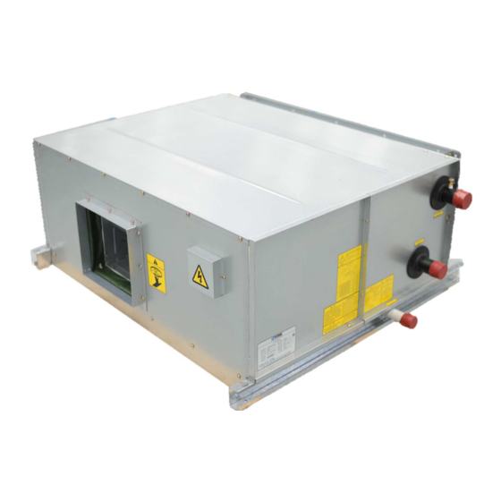
The units are especially suitable for the air-conditioning of commercial buildings and industry applications. YORK YBAH series air handling units have 12 different models. The cooling capacity ranges from 8kW to 252kW, and air flow from 1500m3/h to 15000m3/h. Rated external total pressure ranges from 175Pa to 315 Pa. -
Page 4: Main Technical Data
Unit Instruction Nomenclature: 1-2 Main Technical Data Nominal cooling capacity (kW) Nominal heating capacity (kW) Nominal external total Weight (kg) Airflow Return air Fresh air Return air Fresh air Motor Model Fan type Motor type pressure (Pa) condition condition condition condition power(kW) YBAH1FB-G... - Page 5 Unit Instruction Notes: 1. The weight listed in the table is the shipping weight. The operation weight of unit is about 20% more than the shipping weight. 2. Standard return air cooling conditions: air inlet at 27°C DB/19.5WB; chilled water inlet/outlet at 7°C/12°C.
-
Page 6: Unit Drawing
Unit Instruction 1-3 Unit Drawing Single Fan unit Double Fan Unit Return air Supply air flange size Piping position flange size Model YBAH1FB-G 402.5 75.2 55.2 51.9 72.7 128.5 128.5 343.5 343.5 YBAH02B-G 417.5 75.2 55.2 51.9 72.7 128.5 128.5 343.5 343.5 YBAH2FB-G... -
Page 7: Main Components
3. The condensate pipe connections use 34mm O.D. male threads (thread code R2). 4. All dimensions are SI unit (mm). 1-4 Main Components The main components of York YBAH air handling unit include: Main accessories: YBAH1F-15 adopts SYT series double-inlet forward-inclined centrifugal fan. -
Page 8: T Ioybah Assembly
Unit Instruction YBAH Assembly 1-5-1 TiO2 assembly installation The TiO2 YBAH assembly is installed in the air-inlet of the YBAH unit (The Figure shown as below), which has been installed before ex- factory. Component list of TiO2 YBAH Assembly Connection flange dimension Lamp input Model model... - Page 9 Unit Instruction 1-5-2 Ultraviolet Lamp Installation, disassembling The ultraviolet lamp is delivered with the unit but is not installed in the unit, thus, it should be mounted in the unit before being powered on and put into service. It is recommended to install the lamp according to steps as below before the unit is connected to the external air inlet duct:...
- Page 10 Unit Instruction YBAH10-YBAH15 unit: Step 1 disassemble the fastening screw of Junction box, take off Junction box Step 2 disassemble the fastening screw of side cover plate, remove side cover plate & disjoin the connector of cable take off side cover plate. Step 3 take out nylon filter and front, rear TiO2 aluminum filter Step 4 take out the base of TiO2 Lampe...
- Page 11 Unit Instruction Wiring of TiO2 YBAH Assembly is as follows: 1. TiO YBAH1F assembly ~ TiO YBAH08 assembly YBAH10 assembly ~ TiO YBAH15 assembly 1-5-3 Operation The operating power supply of the sterilizer ultraviolet lamp is a single-phase, 220V.voltage power Do not stare at the ultraviolet lamp for a long time, avoiding any possible injury to your eyes.
-
Page 12: Electrostatic Precipitation
York Company informed of it immediately. Our York Company will not be responsible for any loss of or damage to the sterilizer and the unit occurred during the transportation or after they have been accepted by the receiving party. -
Page 13: Transportation & Installation
If it is found that there is any damage to the unit, describe it in the transportation list and demand a signature for confirmation from the personnel of the transportation company. Otherwise, the York Company will not take any responsibility for it. 2-3 Storage If the unit is stored outdoors, it should be protected against the corrosion from water, moisture, rusting or dust. -
Page 14: Brief Introduction To The Installation
Before the unit starts operation, all dirt in the water collecting tray and the water drain pipe should be removed. Note: If there is dirt on the motor or the fan blades remained, the York Company will not provide any effective maintenance and repairing service. 2-7 Brief Introduction to the Installation... - Page 15 Transportation & Installation 2-7-3 Determination of Water and Directions of the Unit The water inlet and outlet pipe interfaces can be arranged in the right or left side of the unit. With viewing from the unit air inlet (or along the air flow direction), if the water inlet and outlet ducts are at the right side of the unit, the unit is called a Right-style Unit;...
- Page 16 Transportation & Installation Points for Attention during Installation: 1. The unit should be installed horizontally in order to ensure free water drainage and a normal operation. 2. There should not be any foreign substance piled up in the water drain tray; and all foreign matters should be removed from the tray.
-
Page 17: Start, Commissioning And Running
Start, Commissioning and Running Start, Commissioning and Running Check before Start up Check the YBAH unit before it is started: 1. Remove the interior and exterior dust from the unit. 2. Check whether there is any component loose in the unit. 3. -
Page 18: Electric Wiring Diagrams
Start, Commissioning and Running 3-2 Electric Wiring Diagrams Electric connection: 1. The direct start schematic diagram (Fig.1) is for motor up to 5.5kw. The Y-△ start schematic (Fig.2) for motors more than 7.5kw. 2. The dashed lines is provided by customer and it should be connected according to Fig.1 or Fig.2. Please ensure that all connections are tightened. -
Page 19: Fan Part
Start, Commissioning and Running 3-3 Fan Part 1. Switch off the master switch before carrying out an internal inspection to the fan. 2. Check whether the electrical connection device of the unit is in consistent with all circuit diagrams. 3. Check the motor’s name plate and observe whether the rated voltage, phase and circuit are in consistent with the power supply recorded in field. -
Page 20: Adjustment Of Belt & Belt Pulley
Start, Commissioning and Running 3-6 Adjustment of belt & belt pulley Adjustment of smoothness For the belt drive unit, inspect the smoothness of the fan and motor belts with a ruler, that is, points of A, B, C and D should be in the same line; otherwise, it is needed to adjust the smoothness of the belt pulley. Belt Adjustment 1. -
Page 21: Points For Attention During Starting Operation
Start, Commissioning and Running 3-9 Points for Attention during Starting Operation 1. Before the unit starts operation, open the coil gas escape valve and exhaust the air. 2. During the operation of the unit, the water pressure should not be greater than 1.6MPa; the vapor pressure should not be greater than 0.4MPa. -
Page 22: Maintenance And Repairing
Maintenance and Repairing Maintenance and Repairing Filter Part The nylon screen filter of 21mm in thickness is provided with the unit, which can filter dirt such as dust, soot, pollen and other foreign substances. When cleaning the filter, beat the accumulated foreign matters off it. If required, clean it with the warm water filled with liquid detergent, dry it and reassemble it back to the filter frame. -
Page 23: Motor
Maintenance and Repairing Fan Bearing The double suction forward fan used in the YBAH unit is designed with the sealed bearing, the normal service life of which can be up to 75,000 working hours at least. During the constantly improvement and development, we reserve the right of changing the technical specification, size without notice in advance. - Page 24 Maintenance and Repairing...
-
Page 25: Failure Analysis
Failure analysis Failure Analysis 5-1 Low Air Flow Rate The actual static pressure needed in the outside of the unit is greater than the design static pressure and the air flow rate is turned into the static pressure. Thus, the air flow rate is lower than the normal. The loose belt reduces the rotation speed of the fan, resulting in a low air flow rate. - Page 26 YORK Guangzhou Air Conditioning & Refrigeration Co.,Ltd. Phone :( 0763)468 1111 Fax :( 0763)468 1114 © 2021 Johnson Controls, Inc. www.johnsoncontrols.om FORM NO.: 6A6Y-A02C-NA-EN SUPERSEDES: Nothing 6097387 SAP NO.:...