Table of Contents
Advertisement
Quick Links
Model No. NETL15818.0
Serial No.
Write the serial number in the space
above for reference.
Serial Number
Decal
CUSTOMER SERVICE
UNITED KINGDOM
Call: 0330 123 1045
From Ireland: 053 92 36102
Website: iconsupport.eu
E-mail: csuk@iconeurope.com
Write:
ICON Health & Fitness, Ltd.
Unit 4, Westgate Court
Silkwood Park
OSSETT
WF5 9TT
UNITED KINGDOM
AUSTRALIA
Call: 1800 993 770
E-mail: australiacc@iconfitness.com
Write:
ICON Health & Fitness
PO Box 635
WINSTON HILLS NSW 2153
AUSTRALIA
CAUTION
Read all precautions and instruc-
tions in this manual before using
this equipment. Save this manual
for future reference.
USER'S MANUAL
iconeurope.com
Advertisement
Table of Contents

Related Manuals for Pro-Form C 990


Summary of Contents for Pro-Form C 990
- Page 1 Model No. NETL15818.0 Serial No. USER'S MANUAL Write the serial number in the space above for reference. Serial Number Decal CUSTOMER SERVICE UNITED KINGDOM Call: 0330 123 1045 From Ireland: 053 92 36102 Website: iconsupport.eu E-mail: csuk@iconeurope.com Write: ICON Health & Fitness, Ltd. Unit 4, Westgate Court Silkwood Park OSSETT...
-
Page 2: Table Of Contents
TABLE OF CONTENTS WARNING DECAL PLACEMENT ............. . . 2 IMPORTANT PRECAUTIONS . -
Page 3: Important Precautions
IMPORTANT PRECAUTIONS WARNING: To reduce the risk of burns, fire, electric shock, or injury to persons, read all important precautions and instructions in this manual and all warnings on your treadmill before using your treadmill. ICON assumes no responsibility for personal injury or property damage sus- tained by or through the use of this product. - Page 4 21. The treadmill is capable of high speeds. frame securely in the storage position. Do Adjust the speed in small increments to not operate the treadmill while it is folded. avoid sudden jumps in speed. 26. Do not change the incline of the treadmill by 22.
-
Page 5: Before You Begin
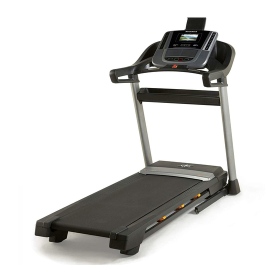
Thank you for selecting the new NORDICTRACK ® manual. To help us assist you, note the product model C 990 treadmill. The C 990 treadmill provides an number and serial number before contacting us. The impressive selection of features designed to make your model number and the location of the serial number workouts at home more effective and enjoyable. -
Page 6: Part Identification Chart
PART IDENTIFICATION CHART Use the drawings below to identify small parts used for assembly. The number in parentheses below each draw- ing is the key number of the part, from the PART LIST near the end of this manual. The number following the key number is the quantity used for assembly. -
Page 7: Assembly
ASSEMBLY • Assembly requires two persons. • Left parts are marked “L” or “Left” and right parts are marked “R” or “Right.” • Place all parts in a cleared area and remove the packing materials. Do not dispose of the packing •... - Page 8 2. Make sure that the power cord is unplugged. Remove the tie securing the Upright Wire (81) to the front of the Base (94). Next, identify the Right Upright (90). Have a sec- ond person hold the Right Upright near the Base (94).
- Page 9 4. Hold the Right Upright (90) against the Base (94). Make sure not to pinch the Upright Wire (81). Attach the Right Upright (90) and a Wheel (25) with two 3/8" x 2 1/4" Screws (7), a 3/8" x 1 1/4" Screw (63), a 3/8"...
- Page 10 7. Hold the right handrail assembly (G) near the Right Upright (90). Insert the Upright Wire (81) into the bottom of the right handrail assembly (G) and out of the front as shown. Attach the right handrail assembly (G) to the Right Upright (90) with two 5/16"...
- Page 11 9. Set the Console Base (64) face down on a soft surface to avoid scratching the Console Base. If there are ties (H) securing the Pulse Crossbar (93) to the Console Base, remove the ties. Remove and discard the four indicated screws (I).
- Page 12 11. IMPORTANT: To avoid damaging the Pulse Crossbar (93), do not use power tools and do not overtighten the #10 x 3/4" Screws (9). Orient the Pulse Crossbar (93) as shown. Attach the Pulse Crossbar to the Handrails (86) with two #10 x 3/4"...
- Page 13 13. Set the console assembly (J) on the brackets on the Handrails (86). Make sure not to pinch any wires. Attach the console assembly (J) with the four 5/16" x 3/4" Screws (4) that you removed in step 9 and four 5/16" Star Washers (11); do not fully tighten the Screws yet.
- Page 14 16. Attach the Tray (31) to the Upright Crossbar (12) with four #8 x 3/4" Screws (2); start all four Screws, and then tighten them. 17. Note: If the treadmill is assembled on a smooth surface, it may roll forward in this step.
- Page 15 18. Remove the 5/16" Nut (34) and the 5/16" x 1 3/4" Bolt (6) from the bracket on the Base (94). Next, orient the Storage Latch (53) as shown. Attach the lower end of the Storage Latch (53) to the bracket on the Base (94) with the 5/16" x 1 3/4"...
- Page 16 20. Firmly tighten the four 3/8" x 2 1/4" Screws (7) and the two 3/8" x 1 1/4" Screws (63). Next, tighten the two 3/8" x 1 3/4" Screws (62); the Wheels (25) must turn freely. Next, set the Left Inner Base Cover (99) onto the lower end of the Left Upright (89).
-
Page 17: How To Use The Treadmill
HOW TO USE THE TREADMILL HOW TO PLUG IN THE POWER CORD Follow the steps below to plug in the power cord. This product must be earthed. If it should malfunc- 1. Plug the indicated end of the power cord into the tion or break down, earthing provides a path of least socket on the treadmill. - Page 18 CONSOLE DIAGRAM FEATURES OF THE CONSOLE compatible heart rate monitor. See page 25 for infor- mation about purchasing an optional chest heart The advanced treadmill console offers a selection of rate monitor. features designed to make your workouts more effec- tive and enjoyable.
- Page 19 HOW TO TURN ON THE POWER HOW TO USE THE TOUCH SCREEN IMPORTANT: If the treadmill has been exposed to The console features a tablet with a full-color touch cold temperatures, allow it to warm to room tem- screen. The following information will help you become perature before you turn on the power.
- Page 20 HOW TO SET UP THE CONSOLE 5. Check for firmware updates. Before using the treadmill for the first time, set up the First, touch the profile button in the lower-right cor- console. ner to select the settings main menu. Next, select the maintenance section.
- Page 21 HOW TO USE THE MANUAL MODE 4. Change the incline of the treadmill as desired. 1. Insert the key into the console. To change the incline of the treadmill, press the incline increase and decrease buttons or one of the See HOW TO TURN ON THE POWER on page numbered incline buttons.
- Page 22 • Your pace To measure your heart rate, stand on the foot rails and hold the contacts with your palms for • The speed of the walking belt approximately ten seconds; avoid moving your hands. When your pulse is detected, your heart •...
- Page 23 HOW TO USE A MAP WORKOUT When you reach the end of the workout, the walking belt will slow to a stop, and a workout Note: To use a map workout, the console must be con- summary will appear on the screen. After you view nected to a wireless network (see HOW TO USE THE the workout summary, touch the Finish button to WIRELESS NETWORK MODE on page 27).
- Page 24 3. Draw your map. 8. Turn on the fan if desired. Navigate to the area on the map where you want See step 7 on page 22. to draw your workout by sliding your fingers on the screen. Tap the screen to add the start point for 9.
- Page 25 4. Log in to your iFit account. THE OPTIONAL CHEST HEART RATE MONITOR If you have not already done so, touch the Login Whether your button to log in to your iFit account. The screen goal is to will ask for your iFit.com username and password. burn fat or to Enter them and touch the Submit button.
- Page 26 HOW TO USE THE EQUIPMENT SETTINGS HOW TO USE THE MAINTENANCE SECTION SECTION 1. Select the settings main menu. 1. Select the settings main menu. See step 1 on page 25. See step 1 on page 25. 2. Select the maintenance section. 2.
- Page 27 4. Calibrate the incline system of the treadmill. Note: You must have your own wireless network and an 802.11b/g/n router with SSID broadcast Touch the Calibrate Incline button. Then, touch the enabled (hidden networks are not supported). Begin button to calibrate the incline system. The treadmill will automatically rise to the maximum When a list of networks appears, touch the desired incline level, lower to the minimum incline level,...
- Page 28 HOW TO USE THE SOUND SYSTEM HOW TO CONNECT AN HDMI CABLE To play music or audio books through the console To show your console screen on a TV or monitor, plug sound system while you exercise, plug a 3.5 mm male an HDMI cable (not included) into the port (F) on the to 3.5 mm male audio cable (not included) into the jack console and into a port on your TV or monitor;...
-
Page 29: How To Fold And Move The Treadmill
HOW TO FOLD AND MOVE THE TREADMILL HOW TO FOLD THE TREADMILL HOW TO MOVE THE TREADMILL To avoid damaging the treadmill, adjust the incline Before moving the treadmill, fold it as described at the to zero before you fold the treadmill. Then, remove left. -
Page 30: Maintenance And Troubleshooting
MAINTENANCE AND TROUBLESHOOTING MAINTENANCE SYMPTOM: The power turns off during use Regular maintenance is important for optimal per- a. Check the power switch (see drawing c at the left). formance and to reduce wear. Inspect and properly If the switch has tripped, wait for five minutes and tighten all parts each time the treadmill is used. - Page 31 Next, locate the c. Your treadmill features a walking belt coated with Reed Switch high-performance lubricant. IMPORTANT: Never (104) and the apply silicone spray or other substances to Magnet (102) the walking belt or the walking platform unless 1/8 in. on the left side instructed to do so by an authorized service of the Pulley...
- Page 32 SYMPTOM: The walking belt slips when walked on SYMPTOM: The treadmill will not connect to the wireless network a. First, remove the key and UNPLUG THE POWER CORD. Using the hex key, turn both idler roller a. Make sure that the wireless settings on the console screws clockwise, 1/4 of a turn.
-
Page 33: Exercise Guidelines
EXERCISE GUIDELINES Burning Fat—To burn fat effectively, you must exer- WARNING: cise at a low intensity level for a sustained period of Before beginning this time. During the first few minutes of exercise, your or any exercise program, consult your physi- body uses carbohydrate calories for energy. -
Page 34: Part List
PART LIST Model No. NETL15818.0 R0718A Key No. Qty. Description Key No. Qty. Description #8 x 1/2" Screw 9/32" Plastic Bushing #8 x 3/4" Screw 3/8" Plastic Bushing 5/16" x 2 1/4" Bolt Storage Latch 5/16" x 3/4" Screw Drive Motor #10 Star Washer Motor Belt 5/16"... - Page 35 Key No. Qty. Description Key No. Qty. Description 3/8" Washer Filter Magnet #8 x 1/2" Machine Screw Clip #8 Nut Reed Switch Motor Isolator Motor Bushing – User’s Manual Note: Specifi cations are subject to change without notice. For information about ordering replacement parts, see the back cover of this manual.
-
Page 36: Exploded Drawing
EXPLODED DRAWING A Model No. NETL15818.0 R0718A... - Page 37 EXPLODED DRAWING B Model No. NETL15818.0 R0718A...
- Page 38 EXPLODED DRAWING C Model No. NETL15818.0 R0718A...
- Page 39 EXPLODED DRAWING D Model No. NETL15818.0 R0718A...
-
Page 40: Ordering Replacement Parts
ORDERING REPLACEMENT PARTS To order replacement parts, please see the front cover of this manual. To help us assist you, be prepared to provide the following information when contacting us: • the model number and serial number of the product (see the front cover of this manual) •...