Table of Contents
Advertisement
Quick Links
Operation &
Maintenance Manual
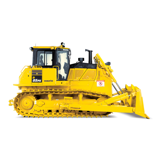
D85EX
D85PX
BULLDOZER
SERIAL NUMBER
D85EX-18
D85PX-18
WARNING
Unsafe use of this machine may cause serious injury or
death. Operators and maintenance personnel must read
this manual before operating or maintaining this
machine. This manual should be kept inside the cab for
reference and periodically reviewed by all personnel who
will come into contact with the machine.
-18
-18
- 22001
and up
- 22001
and up
ORIGINAL INSTRUCTIONS
EENAM03360
Advertisement
Chapters
Table of Contents

Related Manuals for Komatsu D85EX-18


Summary of Contents for Komatsu D85EX-18
- Page 1 Operation & EENAM03360 Maintenance Manual D85EX D85PX BULLDOZER SERIAL NUMBER D85EX-18 - 22001 and up D85PX-18 - 22001 and up WARNING Unsafe use of this machine may cause serious injury or ORIGINAL INSTRUCTIONS death. Operators and maintenance personnel must read this manual before operating or maintaining this machine.
- Page 3 Komatsu or Ko- matsu approved rebuilt parts or assemblies or others parts of equivalent quality, and that the engine be serviced by an authorized Komatsu distribu- tor. Failure to follow these recommendations could result in ineffective serv- ice, damage to the product or safety risks (including personal injury or death).
- Page 4 It is provided on the back side of the operator's seat back. If this manual is lost or damaged, contact Komatsu or your Komatsu distributor and tell them about the machine model name and the serial No. immediately to arrange for its replacement.
-
Page 5: Safety Information
FOREWORD SAFETY INFORMATION SAFETY INFORMATION To enable you to use the machine safely, and to prevent personal injury to operators, service personnel or by- standers, the precautions and warnings included in this manual and the safety signs attached to the machine must always be observed. -
Page 6: Noise
NOISE FOREWORD NOISE Two labels indicating the machine noise level are affixed on the machine. • Sound pressure level at the operator’s station, measured according to ISO 6396 (Dynamic test method, simulated working cycle). The maximum value of the standard deviation of the meas- ured time-averaged A-weighted emission sound pressure level at the operator’s position is 2.5dB, in accordance with ISO 11201... -
Page 7: Vibration Levels
ISO 7096. FOR D85EX-18 : The actual acceleration value for the hands and arms is less than or equal to 2.5 m/s , the uncertainty for this value is 0.73 m/s... - Page 8 VIBRATION LEVELS FOREWORD • Transport machines long distances between worksites The following guidelines can be effective to minimize risks of low back pain • Operate the machine only when you are in good health • Provide breaks to reduce long periods of sitting in the same posture •...
-
Page 9: Introduction
FOREWORD INTRODUCTION INTRODUCTION MAIN USE OF MACHINE This Komatsu machine is designed to be used mainly for the following work: • Dozing work • Leveling work • Cutting or ditching into hard or frozen ground • Works of felling trees and removing stumps •... - Page 10 INTRODUCTION FOREWORD when the machine is equipped with the mirrors and other visibility assistant devices. Be fully aware that there is an area where the operator cannot see when operating the machine. 12m radius visibility The figure below shows a visibility from the machine for a radius of 12m. Shaded area (B) in the figure shows an area whose view is blocked by a part of the machine when the machine is equipped with the mirrors and other visibility assistant devices.
-
Page 11: Engine Technology To Conform Exhaust Gas Emission
Catalytic Reduction (SCR) to conform EU Stage IV emission regulation in the European Union. • Komatsu Diesel Particulate Filter (KDPF): A device which captures diesel particular matter or soot in the exhaust gas to purify exhaust gas. If soot is accumulated to a certain level in the filter, a purification process to burn the soot is performed automatically to keep the filtering performance of KDPF high. -
Page 12: Product Information
PRODUCT INFORMATION FOREWORD PRODUCT INFORMATION When requesting service or ordering replacement parts, inform your Komatsu distributor of the following items. LOCATION OF PRODUCT IDENTIFICATION NUMBER (PIN)/MACHINE SERI- AL NO. PLATE This is at the bottom left at the front of the operator's seat. -
Page 13: Service Meter Location
YOUR MACHINE SERIAL NUMBERS AND DISTRIBUTOR Machine serial No. Engine serial No. Product identification number (PIN) Manufacturers name: KOMATSU LTD. Address: 2-3-6 Akasaka Minato-ku, Tokyo 107-8414 Japan Authorised representative: KOMATSU EUROPE INT. Address: Mechelsesteenweg 586 B-1800 Vilvoorde Belgium Distributor name Address Service personnel Phone/Fax 1-11... -
Page 14: Serial Plate
SERIAL PLATE FOREWORD SERIAL PLATE EI000001 MACHINE DESIGNATION/TYPE ENGINE POWER SERIAL NUMBER PRODUCT IDENTIFICATION NUMBER YEAR OF CONSTRUCTION MANUFACTURER OPERATING MASS AUTHORISED REPRESENTATIVE 1-12... -
Page 15: Declaration Of Conformity
FOREWORD DECLARATION OF CONFORMITY DECLARATION OF CONFORMITY The manufacturer/Authorised representative The manufacturer Authorised representative KOMATSU LTD. KOMATSU EUROPE INT. 2-3-6 Akasaka Mechelsesteenweg 586 Minato-ku, Tokyo 107-8414 B-1800 Vilvoorde Japan Belgium Declares that this machine: D85EX-18 D85PX-18 Fulfils all the relevant provisions of following EC Directives:... -
Page 16: Table Of Contents
TABLE OF CONTENTS FOREWORD TABLE OF CONTENTS FOREWORD..............................1-1 BEFORE READING THIS MANUAL ......................1-2 SAFETY INFORMATION .......................... 1-3 NOISE............................... 1-4 VIBRATION LEVELS ..........................1-5 VIBRATION - OPERATING CONDITION ................... 1-5 GUIDE TO REDUCE VIBRATION LEVELS ON MACHINE ..............1-5 INTRODUCTION ............................ - Page 17 PRECAUTIONS FOR DISCHARGED BATTERY ................3-227 OTHER TROUBLE......................... 3-230 MAINTENANCE............................... 4-1 PRECAUTIONS FOR MAINTENANCE ..................... 4-2 CHECK SERVICE METER READING ....................4-2 KOMATSU GENUINE REPLACEMENT PARTS ................4-2 KOMATSU GENUINE LUBRICANTS ....................4-2 ALWAYS USE CLEAN WASHER FLUID .................... 4-2 1-15...
- Page 18 CONSUMABLE PARTS ........................7-3 RECOMMENDED FUEL, COOLANT, AND LUBRICANT ................7-6 LUBRICATION CHART ........................7-6 METHOD FOR USING FUEL, COOLANT AND LUBRICANTS ACCORDING TO AMBIENT TEMPERA- TURE ............................. 7-8 RECOMMENDED BRANDS AND QUALITIES OTHER THAN KOMATSU GENUINE OILS ....7-9 INDEX................................8-1 1-16...
-
Page 19: Safety
SAFETY Please read and make sure that you fully understand the precautions descri- bed in this manual and the safety labels on the machine. When operating or servicing the machine, always follow these precautions strictly. - Page 20 SAFETY SAFETY SAFETY SAFETY LABELS ............................2-4 LOCATION OF SAFETY LABELS......................2-5 CONTENTS OF SAFETY LABELS ......................2-6 GENERAL PRECAUTIONS COMMON TO OPERATION AND MAINTENANCE ........... 2-10 PRECAUTIONS BEFORE STARTING OPERATION................2-10 ENSURE SAFE OPERATION ......................2-10 UNDERSTAND THE MACHINE ....................... 2-10 PREPARATIONS FOR SAFE OPERATION ....................
- Page 21 SAFETY SAFETY PRECAUTIONS WHEN LOADING AND UNLOADING ..............2-24 TOWING AND BEING TOWED....................... 2-25 PRECAUTIONS FOR TOWING AND BEING TOWED..............2-25 PRECAUTIONS FOR MAINTENANCE ......................2-26 PRECAUTIONS BEFORE STARTING INSPECTION AND MAINTENANCE .......... 2-26 DISPLAY WARNING TAG DURING INSPECTION AND MAINTENANCE ........2-26 KEEP WORK PLACE CLEAN AND TIDY ..................
-
Page 22: Safety Labels
If the safety labels are damaged, lost, or cannot be read properly, replace them with new ones. For details of the part numbers for the safety labels, see this manual or the actual label, and place an order to your Komatsu distributor. •... -
Page 23: Location Of Safety Labels
SAFETY SAFETY LABELS LOCATION OF SAFETY LABELS 1. Caution for operation, inspection and maintenance 8. Stop rotation during inspection and maintenance 2. Caution before moving in reverse 9. Caution for approaching while moving machine 3. Caution when leaving the operator's seat 10. -
Page 24: Contents Of Safety Labels
SAFETY LABELS SAFETY CONTENTS OF SAFETY LABELS (1) Caution for operation, inspection and maintenance (09651- A0641) • Warning ! • Read manual before operation, maintenance, disassembly, assembly and transportation. (2) Caution for safety at rear (09802-B0640) • Sign indicates a hazard of rear working and advancing be- hind. - Page 25 SAFETY SAFETY LABELS (3) Caution when leaving the operator's seat (09654-B0641) • Sign indicates a hazard of unexpected moving of stopped machine. • Lower working device to ground, move safety lever to lock position and take engine key with you before leaving ma- chine.
- Page 26 SAFETY LABELS SAFETY (7) Caution for handling cable (09808-A0881) • Sign indicates an electric hazard handling the cable. • Read manual for safe and proper handling. (8) Stop rotation during inspection and maintenance (09667- A0481) • Sign indicates a hazard of rotating parts, such as belt. •...
- Page 27 If some modification is applied to the ROPS or FOPS, it may effect the strength and may not comply with the standard. Do not drill, cut or weld on the ROPS or FOPS structure. Consult Komatsu Distributor before al- tering.
-
Page 28: General Precautions Common To Operation And Maintenance
GENERAL PRECAUTIONS COMMON TO OPERATION AND MAINTE- NANCE SAFETY GENERAL PRECAUTIONS COMMON TO OPERATION AND MAINTENANCE Mistakes in operation, inspection, or maintenance may result in serious personal injury or death. Before per- forming operation, inspection, or maintenance, always read this manual and the safety labels on the machine carefully and obey the warnings. -
Page 29: Precautions To Prevent Fire
GENERAL PRECAUTIONS COMMON TO OPERATION AND MAINTE- SAFETY NANCE • If water gets into the electrical system, electric devices will cause malfunctions, and the machine will cause error. If the machine cause error, it may move unexpectedly and cause serious personal injury or death. When washing the machine with water or steam, do not allow the water or steam to come into direct contact with electrical compo- nents. -
Page 30: Prevent Fire
Fire around the machine due to highly heated exhaust gas This machine is equipped with Komatsu Diesel Particulate Filter (hereafter KDPF). 2-12... -
Page 31: Precautions When Getting On Or Off Machine
When there are thatched houses, dry leaves or pieces of paper near the job site, set the system to the regener- ation disable to prevent fire hazards due to highly heated exhaust gas during the aftertreatment devices regen- eration. For setting, see “HANDLE Komatsu Diesel Particulate Filter (KDPF) (3-103)”. Explosion caused by lighting equipment •... -
Page 32: Lifting Of Personnel Prohibited
GENERAL PRECAUTIONS COMMON TO OPERATION AND MAINTE- NANCE SAFETY • Never jump on or off the machine. Never get on or off a moving machine. • If the machine starts to move when there is no operator on the machine, do not jump on to the machine and try to stop it. -
Page 33: Do Not Get Caught In Work Equipment
• If the protective structure is damaged or deformed by falling objects or by rolling over, its strength will be reduced and it will not be able to fulfill its function properly. In such cases, always consult your Komatsu distributor. -
Page 34: Precautions When Running Engine Inside Building
GENERAL PRECAUTIONS COMMON TO OPERATION AND MAINTE- NANCE SAFETY PRECAUTIONS WHEN RUNNING ENGINE INSIDE BUILDING The engine exhaust gas contains substances that may damage your health or even cause death. Start or operate the engine in a place where there is good ventilation. If the engine or ma- chine must be operated inside a building or underground, where the ventilation is poor, take steps to ensure that the en- gine exhaust gas is removed and that ample fresh air is... -
Page 35: Precautions For Operation
SAFETY PRECAUTIONS FOR OPERATION PRECAUTIONS FOR OPERATION PRECAUTIONS FOR JOBSITE INVESTIGATE AND CONFIRM JOBSITE CONDITIONS On the jobsite, there are various hidden dangers that may lead to serious personal injury or death. Before start- ing operations, always check the following to confirm that there is no danger on the jobsite. •... -
Page 36: Ensure Good Visibility
PRECAUTIONS FOR OPERATION SAFETY Voltage of Cables Safety Distance 154000 V Min. 5 m 187000 V Min. 6 m 275000 V Min. 7 m 500000 V Min. 11 m • To prepare for any possible emergencies, wear rubber shoes and gloves. Lay a rubber sheet on the opera- tor's seat, and be careful not to touch the chassis with any exposed part of your body. -
Page 37: Start Engine
Always observe the regulations for jobsite and environmental standards. This machine does not contain asbestos, but any part which is not the genuine part, it has risk of containing asbestos. Always use Komatsu genuine parts. START ENGINE USE WARNING TAGS If there is a "DANGER! Do NOT operate!"... -
Page 38: Precautions When Starting Engine
PRECAUTIONS FOR OPERATION SAFETY • Before starting the engine, check that work equipment lock lever (1) and parking brake lever (2) are in LOCK positions (L). • Adjust the mirrors to have a good rear view from the oper- ator's seat. For the adjustment, see “METHOD FOR ADJUSTING MIRRORS (3-151)”. -
Page 39: Precautions For Operation
SAFETY PRECAUTIONS FOR OPERATION • When disconnecting the jumper cables, take care not to bring the clips in contact with each other or with the machine. • For the starting procedure with the jumper cables, see OPERATION, “START ENGINE WITH JUMPER CA- BLES (3-229)”. -
Page 40: Precautions When Traveling On Slopes
PRECAUTIONS FOR OPERATION SAFETY • When traveling on a level ground, keep the work equip- ment approximately 40 to 50 cm above the ground. If that height is not maintained between the work equipment and the ground, the work equipment may get stuck in the ground and the machine may tip over. -
Page 41: When Operating
SAFETY PRECAUTIONS FOR OPERATION WHEN OPERATING • Be careful not to approach too close to the edge of cliffs. When making embankments or landfills, or when dropping soil over a cliff, dump one pile, then use the next pile of soil to push the first pile. •... -
Page 42: Precautions For Transportation
• This machine needs to be divided into components for transportation depending on the regulation. When transporting the machine, consult your Komatsu distributor. PRECAUTIONS WHEN LOADING AND UNLOADING If handling is wrong when loading or unloading the machine, it is dangerous that the machine may tip over or fall. -
Page 43: Towing And Being Towed
SAFETY PRECAUTIONS FOR OPERATION • When on the ramps, do not operate any lever except for the travel lever (travel forward and reverse). • Never correct your steering on the ramps. If necessary, drive off the ramps onto the ground, correct the di- rection, then enter the ramps again. -
Page 44: Precautions For Maintenance
PRECAUTIONS FOR MAINTENANCE SAFETY PRECAUTIONS FOR MAINTENANCE PRECAUTIONS BEFORE STARTING INSPECTION AND MAINTENANCE DISPLAY WARNING TAG DURING INSPECTION AND MAINTENANCE During inspection and maintenance, always display the "DAN- GER! Do NOT operate!" warning tag. If there is a "DANGER! Do NOT operate!" warning tag dis- played, it means that someone is performing inspection and maintenance of the machine. -
Page 45: Two Workers For Maintenance When Engine Is Running
SAFETY PRECAUTIONS FOR MAINTENANCE • Lower the work equipment completely to the ground and stop the engine before performing any inspection and maintenance. • Turn the starting switch to ON position, set work equip- ment lock lever (2) to FREE position (F), operate the blade control lever and the ripper control lever to RAISE and LOWER position 2 to 3 times repeatedly to release the re- maining pressure in the hydraulic circuit, then set parking... -
Page 46: Precautions When Installing, Removing, Or Storing Attachments
PRECAUTIONS FOR MAINTENANCE SAFETY • Set work equipment lock lever (1) and parking brake lever (2) to LOCK positions (L) to prevent the work equipment from moving. • Do not touch the control levers. When it is necessary to operate the control levers, always give a signal to your fel- low workers to evacuate them to a safe place. -
Page 47: Precautions For Inspection And Maintenance
SAFETY PRECAUTIONS FOR MAINTENANCE • It is extremely dangerous to work under the machine if the track shoes are lifted off the ground and the machine is supported only with the work equipment. If any of the con- trol levers is touched by accident, or there is damage oc- curring to the hydraulic piping, the work equipment or the machine will suddenly fall. -
Page 48: Precautions When Using Hammer
PRECAUTIONS FOR MAINTENANCE SAFETY • Do not use or charge the battery if the battery electrolyte is below LOWER LEVEL mark. This may cause an explosion. Always perform periodic inspection of the battery electrolyte level, and add purified water (such as a commercial battery fluid) to UPPER LEVEL mark. •... -
Page 49: Precautions For High-Temperature Coolant
SAFETY PRECAUTIONS FOR MAINTENANCE • If hard metal parts such as pins, bucket teeth, cutting edges, or bearings are hit with a hammer, pieces might be scattered, and it may cause serious personal injury or death. Always wear protective eyeglasses and gloves. •... -
Page 50: Precautions For High-Pressure Fuel
If the hose or piping mounts are loose or oil or fuel is found to be leaking from the mount, stop operations and tighten to the specified torque. If any damaged or deformed hoses or piping are found, consult your Komatsu distributor. Replace the hose if any of the following problems are found. -
Page 51: Precautions For High-Pressure Grease When Adjusting Track Tension
If it is disassembled by mistake, the spring may shoot out and cause serious personal injury or death. If it is necessary to disassemble it, ask your Komatsu distributor to perform the work. HANDLE ACCUMULATOR This machine is equipped with an accumulator. -
Page 52: Precautions For Compressed Air
Do not hit or roll it, or subject it to any impact. • When disposing of the accumulator, the gas must be re- leased. Ask your Komatsu distributor to perform this work. PRECAUTIONS FOR COMPRESSED AIR • When performing cleaning with compressed air, there is a hazard of serious personal injury or death caused by flying dust or particles. - Page 53 SAFETY PRECAUTIONS FOR MAINTENANCE • Replace or repair the defined life parts if any defect is found, even when they have not reached the speci- fied replacement time. 2-35...
-
Page 54: Precautions For Def
PRECAUTIONS FOR DEF SAFETY PRECAUTIONS FOR DEF GENERAL CHARACTER AND PRECAUTIONS FOR HANDLING DEF is a colorless transparent 32.5% aqueous urea solution. Urea as main constituent is a material which is used for cosmetics, medical and pharmaceutical products, and fertilizer, etc. The following situations require im- mediate action: •... -
Page 55: Operation
OPERATION Please read and make sure that you understand the SAFETY section before reading this section. -
Page 56: General View
GENERAL VIEW OPERATION GENERAL VIEW MACHINE EQUIPMENT NAME (Sigma dozer) (1) Blade (7) Blade tilt cylinder (2) Blade lift cylinder (8) Frame (3) Multi-shank ripper (9) Idler (4) Sprocket (10) Track frame (5) Track (11) Ripper lift cylinder (6) ROPS cab (12) Rearview camera (if equipped) - Page 57 OPERATION GENERAL VIEW (13) SCR (17) DEF pump (14) DEF injector (18) DEF tank (15) Komatsu Diesel Particulate Filter (hereinafter (19) Battery disconnect switch KDPF) (20) System operating lamp (16) Komatsu Closed Crankcase Ventilation (hereafter KCCV) ventilator...
-
Page 58: Controls And Gauges Names
GENERAL VIEW OPERATION CONTROLS AND GAUGES NAMES (1) Cigarette lighter (9) Starting switch (2) Parking brake lever (10) Brake pedal (3) Fuel control dial (11) Decelerator pedal (4) Joystick (steering, directional and gear shift lever) (12) Work equipment lock lever (5) Rear lamp switch (13) Blade control lever (6) Headlamp switch... - Page 59 OPERATION GENERAL VIEW MACHINE MONITOR EQUIPMENT NAME AA: Standard screen, BB: Check before starting screen, CC: Maintenance time warning screen (1) Air conditioner control switch (17) Message display (2) Buzzer cancel switch (18) Operation mode pilot lamp (3) Operation mode selector switch (19) Air conditioner pilot lamp (4) Gear-shift mode selector switch (20) Preheating pilot lamp...
-
Page 60: Explanation Of Components
EXPLANATION OF COMPONENTS OPERATION EXPLANATION OF COMPONENTS The following is an explanation of devices necessary to operate the machine. To perform suitable operations correctly and safely, it is important to completely understand methods of operat- ing the equipment, and the meanings of the displays. EXPLANATION OF MACHINE MONITOR EQUIPMENT AA: Standard screen, EE: Warning or Error screen, DD: Guidance screen (1) Warning display... - Page 61 OPERATION EXPLANATION OF COMPONENTS BASIC OPERATION OF MACHINE MONITOR BASIC OPERATION OF MACHINE MONITOR WHEN STARTING ENGINE IN NOR- MAL SITUATION When camera is not set • When the starting switch is turned to ON position, the opening screen GG is displayed. •...
- Page 62 EXPLANATION OF COMPONENTS OPERATION When camera is set • When the starting switch is turned to ON position, the opening screen GG is displayed. • After the opening screen GG is displayed for 2 seconds, the screen switches to the camera image FF. •...
- Page 63 End screen when any message has been re- ceived If there is any message from your Komatsu distributor, it is dis- played on the end screen. In this case, turn the starting switch to ON position to re-check the message, and if the message is requesting a response, make a reply to it.
- Page 64 F1, and the screen changes to the Check Before Starting screen BB without inputting ID number. REMARK • Contact your Komatsu distributor for details of the method of setting, changing, or canceling the operator identifica- tion function. • Depending on the set value of ID holding time, even if in-...
- Page 65 Be careful not to use it for the purpose of security enhance- ment. Komatsu cannot accept any responsibility for any loss or damage resulting from the wrong use of ID or unauthorized use of ID by a third person.
- Page 66 EXPLANATION OF COMPONENTS OPERATION If there is any abnormality currently generated, “!” is displayed on top of switch F5. Press switch F5 to check the detail of the current abnormality. The “Current Abnormality” screen is displayed. BASIC OPERATION OF MACHINE MONITOR WHEN TROUBLE OCCURS WHILE OPERATING MACHINE If any abnormality occurs during operation, the standard screen AA changes to the abnormality screen EE.
- Page 67 OPERATION EXPLANATION OF COMPONENTS If there is any error existing, “!” is displayed on top of switch F5. Press switch F5 to check the detail of the current abnormality. The “Current Abnormality” screen is displayed. WARNING DISPLAY NOTICE Appearance of any of action levels “L01” to “L04” on the machine monitor indicates presence of an ab- normality of the machine.
- Page 68 EXPLANATION OF COMPONENTS OPERATION (1) Action level display (6) Hydraulic oil temperature caution lamp (2) Caution lamp (7) DEF level caution lamp (3) Caution lamp (8) Fuel level caution lamp (4) Engine coolant temperature caution lamp (9) Power train oil temperature caution lamp (5) Engine speed caution lamp (*) (10) Caution lamp (*): Displayed items change according to setting of the multi-gauge.
- Page 69 │ no load or stop it. Sounds inter- Lights up in │ mittently If the condition is not improved, ask your Komatsu distributor │ for inspection and maintenance. │ Some functions may be restricted from use, but the machine ↓...
- Page 70 EXPLANATION OF COMPONENTS OPERATION CAUTION LAMP LIST NOTICE • These caution lamps do not guarantee the condition of the machine. Do not simply rely on the caution lamp when performing checks before starting (start-up inspec- tion). Always get off the machine and check each item directly. •...
- Page 71 OPERATION EXPLANATION OF COMPONENTS Display color/Machine condition (Action level) Symbol Type of caution lamp Yellow Blue White Abnormal Abnormal KDPF system caution lamp (L04, L03) (L01) Abnormal Accumulated KDPF soot accumulation caution lamp (L03) (L01) Abnormal Sensing is DEF level caution lamp Normal disabled (L04, L03)
- Page 72 EXPLANATION OF COMPONENTS OPERATION Display color/Machine condition (Action level) Symbol Type of caution lamp Yellow Blue White Abnormal Air conditioner system caution lamp (L01) Seat belt un- Seat belt caution lamp fastened Due time is Maintenance time caution lamp Notice over For the meaning of each caution lamp and the action to take for it, see the section of each caution lamp.
- Page 73 OPERATION EXPLANATION OF COMPONENTS F1: Displays the next page. When on the last page, it displays the first page. F2: Displays the previous page. When on the first page, it dis- plays the last page. F5: Returns the screen to the standard screen. ENGINE COOLANT TEMPERATURE CAUTION LAMP Engine coolant temperature caution lamp warns about states caused by engine coolant temperature.
- Page 74 When action level “L03” is displayed The caution lamp lights up in red and the alarm buzzer sounds intermittently. Stop the operation and move the machine to a safe place, then ask your Komatsu distributor for inspection and maintenance. When action level “L01” is displayed The caution lamp lights up in yellow.
- Page 75 When action level “L03” is displayed The caution lamp lights up in red and the alarm buzzer sounds intermittently. Stop the operation and move the machine to a safe place, then ask your Komatsu distributor for inspection and maintenance. When action level “L01” is displayed The caution lamp lights up in yellow.
- Page 76 When action level “L03” is displayed The caution lamp lights up in red and the alarm buzzer sounds intermittently. Stop the operation and move the machine to a safe place, then ask your Komatsu distributor for inspection and maintenance. When action level “L01” is displayed The caution lamp lights up in yellow.
- Page 77 Much soot is accumulated in KDPF, however, the operation can be performed. After the operation is finished, move the machine to a safe place and perform manual stationary regeneration. REMARK For details of the manual stationary regeneration, see “HANDLE Komatsu Diesel Particulate Filter (KDPF) (3-103)”. DEF LEVEL CAUTION LAMP DEF level caution lamp alerts when DEF tanlk level becomes low.
- Page 78 Whenever the caution lamp lights up in yellow, it is necessary to ask your Komatsu distributor to go off this caution lamp. When stopping the engine, stop it after running it at low idle for approximately 5 minutes. For details, see “METHOD FOR STOPPING ENGINE (3-166)”.
- Page 79 OPERATION EXPLANATION OF COMPONENTS Stop the work, move the machine to a safe place, and then ask your Komatsu distributor for inspection and maintenance. When action level “L01” is displayed The caution lamp lights up in yellow. Some functions may be restricted for use, but the machine can operate.
- Page 80 EXPLANATION OF COMPONENTS OPERATION When you finish the operation, always have the inspection and maintenance performed. Ask your Komatsu distributor for inspection and maintenance as needed. ENGINE OIL PRESSURE CAUTION LAMP Engine oil pressure caution lamp warns about abnormality of engine lubricating oil pressure.
- Page 81 The caution lamp lights up in yellow and indicates action level “L01”. The air conditioner system has abnormality. Ask your Komatsu distributor for inspection and maintenance as soon as possible. MAINTENANCE TIME CAUTION LAMP Maintenance time caution lamp displays notices and alarms concerning maintenance time.
- Page 82 • The lighting time of maintenance due time notice (yellow) has been initially set to 30 hours, but it can be changed. To change the setting, ask your Komatsu distributor. • For operations on the “Maintenance” screen, see “MAIN- TENANCE SCREEN SETTING (3-68)”.
- Page 83 OPERATION EXPLANATION OF COMPONENTS (3) Work equipment lock pilot lamp (9) Preheating pilot lamp (4) Aftertreatment devices regeneration pilot lamp (10) Fan reverse pilot lamp (5) Aftertreatment devices regeneration disable pilot (11) Reverse travel slow mode pilot lamp lamp (12) Guidance display (6) Message display (13) Gear speed display (7) Operating mode display...
- Page 84 Pilot lamp goes out: Air conditioner OFF MESSAGE DISPLAY The User Message is displayed when there is a message from Komatsu. To read the message, see “MESSAGE DISPLAY (3-80)”. Lights up in green (A): There is unread message. Lights up in blue (B): There is any read message to which no reply is made.
- Page 85 When there are thatched houses, dry leaves or pieces of paper near the job site, set the system to the regeneration disable to prevent fire hazards due to highly heated exhaust gas during aftertreat- ment devices regeneration. For details of the setting method, see “HANDLE Komatsu Diesel Partic- ulate Filter (KDPF) (3-103)”.
- Page 86 EXPLANATION OF COMPONENTS OPERATION PARKING BRAKE PILOT LAMP The parking brake pilot lamp lights up when the parking brake is in LOCK position. It goes out when the parking brake lever is set to FREE posi- tion. When the parking brake lever needs to be set to LOCK posi- tion, the parking brake pilot lamp flashes.
- Page 87 OPERATION EXPLANATION OF COMPONENTS Guidance to avoid hydraulic relief If the hydraulic oil is kept relieved for more than 10 seconds during operation, the hydraulic relief deterrence message is displayed on the machine monitor. The hydraulic relief deterrence message goes out 5 seconds later or when switch F5 is pressed.
- Page 88 EXPLANATION OF COMPONENTS OPERATION When the time until engine output power limitation starts is 1 to 8 hours “Approx. * hours remaining to DEF refill caution.” is displayed. When the time until engine output power limitation starts is less than 1 hour “DEF refill caution will appear soon.”...
- Page 89 OPERATION EXPLANATION OF COMPONENTS SPEED RANGE DISPLAY The gear speed display section indicates the following informa- tion. The travel gear speed of the machine (“F1” for FORWARD 1st, “R2” for REVERSE 2nd) is displayed in top left area (a). The gear shift mode is displayed in top right area (b). The preset mode is displayed in bottom area (c).
- Page 90 EXPLANATION OF COMPONENTS OPERATION When the engine is started, if the indicator is in position (D), perform the warm-up operation. For details, see “METHOD FOR ENGINE WARM-UP OPERATION (3-164)”. Display (H) when temperature is proper: Back ground (K) of en- gine coolant temperature caution lamp lights up in blue.
- Page 91 OPERATION EXPLANATION OF COMPONENTS HYDRAULIC OIL TEMPERATURE GAUGE Hydraulic oil temperature gauge shows the hydraulic oil tem- perature. If the indicator is in green range during operations, it is normal. If the indicator goes beyond red range (A) during operations, the overheat prevention system operates.
- Page 92 EXPLANATION OF COMPONENTS OPERATION SERVICE METER/CLOCK The service meter/clock shows the total hours of operation of the machine or the present time. When the engine is running, the service meter advances even when the machine is not moving. The service meter advances 0.1 every 6 operation minutes, regardless of the engine speed.
- Page 93 OPERATION EXPLANATION OF COMPONENTS ECO GAUGE / DRAWBAR PULL GAUGE The ECO gauge/ drawbar pull gauge displays ECO gauge (in- stantaneous fuel consumption) (C) or drawbar pull gauge (work load) (D). The instantaneous fuel consumption means the fuel consump- tion rate at each moment, which varies with the work load and engine speed.
- Page 94 EXPLANATION OF COMPONENTS OPERATION REMARK • Immediately after turning the starting switch to ON position and during the engine is running, DEF level cau- tion lamp (1) lights up in white. However, this does not indicate abnormality. • In cold weather, DEF level cannot be detected and DEF level caution lamp (1) lights up in white for approxi- mately 1 hour.
- Page 95 OPERATION EXPLANATION OF COMPONENTS (A) Switch F2: Multi-gauge selector switch (B) Switch F3: Camera image selector switch. (C) Switch F4: Service meter / clock display selector switch (D) Switch F5: Current Abnormality display switch (Only while caution lamp is lit) (E) Switch F5: Energy saving (ECO) guidance erase switch (While ECO guidance is displayed) (F) Switch F6: User menu display switch...
- Page 96 EXPLANATION OF COMPONENTS OPERATION (I) Switch F3: Moves to the item below (forward). (When on the last line, it moves to the first line on the next page.) (J) Switch F4: Moves to the item above (backward). (When on the first line, it moves to the last line on the previous page.) (K) Switch F5: To cancel any change and return to the previous screen.
- Page 97 OPERATION EXPLANATION OF COMPONENTS WORKING MODE SELECTOR SWITCH The operating mode selector switch is used for switching the working mode of the engine. Normally, it is possible to perform all operations in E mode, and this mode reduces fuel consumption. Compared with E mode, P mode has more power, but the fuel consumption increases.
- Page 98 EXPLANATION OF COMPONENTS OPERATION After the setting change of each item is complete, press switch F2. The memory saving screen is displayed. Check the setting of each item (on the left of the screen). Press switch F3 or F4 to move the yellow cursor to a mem- ory number (“M1”...
- Page 99 OPERATION EXPLANATION OF COMPONENTS REVERSE SLOW MODE SWITCH The reverse slow mode switch is used for setting and canceling the reverse slow mode. While the reverse slow mode is set, reverse slow mode pilot lamp lights up on the screen of the machine monitor. When the reverse slow mode is set, it is possible to throttle down the engine speed automatically to decrease the reverse speed.
- Page 100 EXPLANATION OF COMPONENTS OPERATION CAMERA IMAGE SELECTOR SWITCH On the standard screen, press switch F3 to switch to the cam- era image display. • On machines not equipped with a camera, the guidance icon related to switch F3 is not displayed. Even if switch F3 is pressed, the screen will not switch to the camera image display.
- Page 101 OPERATION EXPLANATION OF COMPONENTS • It is possible to change the operation mode by pressing the operation mode selector switch. For the operation mode selector switch, see “WORKING MODE SELECTOR SWITCH (3-43)”. When the operation mode is changed, the screen returns automatically to the standard screen.
- Page 102 EXPLANATION OF COMPONENTS OPERATION Actions against warning during camera image display • If any error or warning occurs on the machine while the camera image is displayed, the caution lamp flashes at the top left of the screen. • If the caution lamp is displayed, press switch F6 to return to the standard screen, and check the content of the ab- normality or warning display.
- Page 103 OPERATION EXPLANATION OF COMPONENTS SERVICE METER/CLOCK DISPLAY SELECTOR SWITCH By pressing switch F4, you can switch the service meter and clock display on the standard screen. If you press switch F4 while the clock is displayed, the service meter is displayed instead of the clock. If you press switch F4 while the service meter is displayed, the clock is displayed instead of the service meter.
- Page 104 EXPLANATION OF COMPONENTS OPERATION METHOD FOR USING MULTI GAUGE The multi-gauge can display the following items. Multi-gauge selection item Remarks Engine speed There is a caution Machine speed Work equipment pump pressure Engine oil pressure With caution lamp Battery voltage With caution lamp Drawbar pull Load graph...
- Page 105 OPERATION EXPLANATION OF COMPONENTS Engine oil pressure (1) 0.0 MPa {0 kg/cm (2) 0.2 MPa {2 kg/cm (3) 0.3 MPa {3 kg/cm (4) 0.4 MPa {4 kg/cm (5) 0.5 MPa {5 kg/cm (6) 0.7 MPa {7 kg/cm Battery voltage (1) 0 V (2) 15 V (3) 20 V (4) 25 V (5) 30 V (6) 31 V Drawbar pull (1) 0 W (2) 0.2 W (3) 0.4 W...
- Page 106 EXPLANATION OF COMPONENTS OPERATION Clock display USER MENU DISPLAY SWITCH On the standard screen, press switch F6 to display the user menu screen on which you can make various settings for the machine in the monitor display. 3-52...
- Page 107 OPERATION EXPLANATION OF COMPONENTS USER MENU The user menu consists of the following kinds. Press switches F1 and F2 to move to right and left for selecting menu screens. (a) “Energy Saving Guidance” (b) “Machine Setting” (c) “Aftertreatment Devices Regeneration” (d) “SCR Information”...
- Page 108 EXPLANATION OF COMPONENTS OPERATION (d) “SCR Information” • Check of DEF level • Information on DEF system (e) “Maintenance” • Check and reset of various maintenance times (f) “Monitor Setting” • Screen Adjustment • Screen Adjustment (camera) • Clock adjustment •...
- Page 109 OPERATION EXPLANATION OF COMPONENTS F1: Moves to the left menu. When on the left end menu, it moves to the right end menu. F2: Moves to the right menu. When on the right end menu, it moves to the left end menu. F3: Moves to the next item (1 line below).
- Page 110 EXPLANATION OF COMPONENTS OPERATION CHECK OPERATION RECORDS Select the Operation Records (1) from the Energy Saving Guid- ance menu screen, then press switch F6. On the Operation Records menu, the working hours, Average Fuel Consumption, Actual working hours, Ave. Fuel Consump- tion (Actual Working), Fuel Consumption, Idling Hours and E mode time ratio on daily basis or on a split measurement peri- od basis are displayed.
- Page 111 OPERATION EXPLANATION OF COMPONENTS Operations on “ECO Guidance Records” screen Press switch F5 to perform the following operation on the “ECO Guidance Records” screen. F5: Returns the screen to the “Energy Saving Guidance” screen. REMARK ECO guidance denotes displaying the guidance for energy sav- ing operation.
- Page 112 EXPLANATION OF COMPONENTS OPERATION Operation on the Average Fuel Consumption Record screen Press switch F1, F2 or F5 on the Average Fuel Consumption Record screen to perform the following operations. F1: Clears the graph data. F2: Switches graphical displays of the average fuel consump- tion.
- Page 113 OPERATION EXPLANATION OF COMPONENTS Deleting the average fuel consumption records When switch F1 (CLEAR) is pressed, the reconfirmation screen shown in the figure is displayed. When the switch F6 is pressed, graphs of data of the last 12 hours and the last 1 week are both deleted, and the screen returns to the Average Fuel Consumption Record screen.
- Page 114 EXPLANATION OF COMPONENTS OPERATION SET DISPLAY OF FUEL CONSUMPTION GAUGE It is possible to change the display of fuel consumption gauge (5) and the setting of Display/Non-display. Select “Average Fuel Consumption Display” (6) from “Con- figurations” screen, then press switch F6. On this screen, it is possible to perform the following oper- ations with switches F3 to F6.
- Page 115 OPERATION EXPLANATION OF COMPONENTS REMARK When you select the split measurement, measurement stop switch F1 (“STOP”) is displayed on the “Operation Records” screen and the “ECO Guidance Records” screen. When you stop the measurement, select “Operation Records” (1) screen or “ECO Guidance Records” (2) screen on “Energy Saving Guidance”...
- Page 116 EXPLANATION OF COMPONENTS OPERATION Select “ECO Gauge display” (8) from “Configurations” screen, then press switch F6. The “ECO Gauge Display” screen appears. “Traction”: Displays drawbar pull gauge (A) on the stand- ard screen. “Fuel Consump”: Displays ECO gauge (B) on the standard screen.
- Page 117 OPERATION EXPLANATION OF COMPONENTS SWITCH DISPLAY/NON-DISPLAY OF ECO GUIDANCE It is possible to change the setting of Display/Non-display of ECO guidance (10). Select “ECO Guidance display” (11) from “Configurations” screen, then press switch F6. “ECO Guidance Display” setting screen appears. ON: Displays ECO Guidance (10) on the standard screen.
- Page 118 EXPLANATION OF COMPONENTS OPERATION The setting screen for ECO Guidance Display at Key OFF screen appears. ON: Displays ECO Guidance (12) on the end screen. OFF: Does not display ECO Guidance (12) on the end screen. On this screen, it is possible to perform the following operations with switches F3 to F6.
- Page 119 OPERATION EXPLANATION OF COMPONENTS REMARK If the fan reverse operation is performed while aftertreatment devices regeneration pilot lamp (A) is lit, the engine speed may not increase even if the fuel control dial is set to High idle (MAX) position, but this is not a failure. The hydraulic fan reverse mode (fan reverse rotation) can be used to remove insects and dirt sticking to the radiator core by blowing air with the fan outward of the machine.
- Page 120 EXPLANATION OF COMPONENTS OPERATION 10. Since fan reverse rotation is set, start the engine. After the engine is started, the machine monitor screen displays as shown in the figure. If the parking brake lever or work equipment lock lever is set to FREE position while the fan is rotated in reverse, the screen shown in the figure is displayed.
- Page 121 OPERATION EXPLANATION OF COMPONENTS AUTO IDLE STOP TIMER SETTING The auto idle stop function stops the engine automatically when the engine is operated continuously at idle with the lock lever in LOCK position for a set time. The auto idle stop function operates when the following conditions are satisfied. •...
- Page 122 For details of aftertreatment devices regeneration, see “HAN- DLE Komatsu Diesel Particulate Filter (KDPF) (3-103)”. The operation methods and the contents of the display of KDPF regeneration and urea SCR regeneration are common.
- Page 123 • If you want to change the setting for the maintenance time or maintenance notice time (initial setting: 30 hours), consult your Komatsu distributor. Operations on “Maintenance Due Time Reset” screen On the “Maintenance” screen, if switch F6 is kept pressed for at least 1.5 seconds, the screen changes to the “Maintenance Due Time Reset”...
- Page 124 EXPLANATION OF COMPONENTS OPERATION Press switch F6 on the “Maintenance Due Time Reset” screen. The screen switches to the reconfirmation screen. REMARK • When canceling the reset, press switch F5. The screen returns to the “Maintenance” screen. • On the “Maintenance Due Time Reset” screen, if no switch is operated for more than 30 seconds, the screen automatically changes to the “Maintenance”...
- Page 125 The guide lines indicate blade width lines and a line 5 m away from the rear of the machine. When changing the blade, ask your Komatsu distributor for adjustment of the camera screen. Select camera screen adjustment on the monitor setting menu screen.
- Page 126 EXPLANATION OF COMPONENTS OPERATION F5: Cancels the change of setting and returns to the monitor setting menu screen. F6: Changes the setting and returns to the monitor setting menu screen. ADJUST CAMERA IMAGE BRIGHTNESS Select Brightness Adjustment on the Camera Screen Ad- justment menu.
- Page 127 OPERATION EXPLANATION OF COMPONENTS F4: Moves to the previous item (1 line above). When on the first line, it moves to the last line on the previous page. F5: Cancels the setting and returns to the Screen Adjustment (Camera) screen. F6: Change the setting and returns to the Screen Adjustment (Camera) screen.
- Page 128 EXPLANATION OF COMPONENTS OPERATION The screen switches to the Clock Adjustment screen for selecting a menu. The following 5 items can be changed. (a): GPS Synchronization (b): Calendar (c): Time (d): 12h/24h Mode (e): Daylight Saving Time REMARK • (b) Calendar and (c) Time need to be readjusted since they are reset after a long-term storage.
- Page 129 OPERATION EXPLANATION OF COMPONENTS The “Calendar” screen is displayed. When year display (A) is highlighted in yellow, operate the switches as follows to change year display (A). If it is not necessary to change the year setting, press switch F6. F3: Calendar goes back 1 year.
- Page 130 EXPLANATION OF COMPONENTS OPERATION The “Time” screen is displayed. When the hour display (D) is highlighted in yellow, operate the switches as follows to change hour display (D). If it is not necessary to change the hour setting, press switch F6. F3: The time goes back 1 hour.
- Page 131 OPERATION EXPLANATION OF COMPONENTS Select “Daylight Saving Time” (e) on “Clock Adjustment” screen, then press switch F6. The “Daylight Saving Time” screen is displayed. F3: Moves to the next item (1 line below). Moves to the top line when on the bottom line. F4: Moves to the previous item (1 line above).
- Page 132 The “Operator ID” menu is not displayed when the operator identification function is disabled. REMARK Contact your Komatsu distributor for details of the method of setting, changing, or canceling the operator identi- fication function. WHEN OPERATOR IDENTIFICATION FUNCTION IS AVAILABLE WITH SKIP When the starting switch is ON and ID is inputted, the identified ID is displayed in the column of “Operator ID”...
- Page 133 OPERATION EXPLANATION OF COMPONENTS • Input the already registered ID on the operator ID changing screen and press F6. Then, the identified ID can be changed. A message is displayed below and the screen returns to the Monitor Setting menu screen. On the Monitor Setting menu screen, the inputted ID is displayed in the column of “Operator ID”.
- Page 134 In this case, the identified ID is not changed. MESSAGE DISPLAY On machines equipped with KOMTRAX, you can see the mes- sages from your Komatsu distributor on this User Message menu (g). When there is any message, the User Message at the top of the standard screen lights up.
- Page 135 When the message display lights up in blue (B), it means that no reply has been made yet to any read message to your Komatsu distributor. Reply to the message in accord- ance with the replying method mentioned below: •...
-
Page 136: Switches
EXPLANATION OF COMPONENTS OPERATION The selected item number is written in place (5) of the message text. • Input the number by using the monitor panel switch. Each switch corresponds to the value shown on the right side below the switch. •... - Page 137 OPERATION EXPLANATION OF COMPONENTS STARTING SWITCH Starting switch is used to start or stop the engine. (A): OFF position The key can be inserted or withdrawn. Switches for the electri- cal system (except room lamp) are all turned off, and the en- gine is stopped.
- Page 138 EXPLANATION OF COMPONENTS OPERATION REMARK Use the cigarette lighter while engine is running. WIPER SWITCH The wiper switch operates the windshield wiper. The wiper switches are as follows. (LH) Left door (FF) Front window (RH) Right door (RR) Rear window (INT) Wiper intermittent operation switch REMARK If the wiper blade is locked for some reason, the wiper stops...
- Page 139 • When installing the cab, perform the operation in accord- ance with the cab installation procedure manual held by your Komatsu distributor. (A) For left (blue) (B) For right (red) (C) For rear (black)
- Page 140 • Use the engine shutdown secondary switch only in an emergency. Immediately ask your Komatsu distributor for repair of the problem. • If this switch is set to the “STOP ENGINE” position by mistake while the machine is operating nor- mally, “Engine Shutdown Secondary Switch Activated”...
- Page 141 OPERATION EXPLANATION OF COMPONENTS Raise cover (C) and open it. Turn the engine shutdown secondary switch to upper posi- tion (a) and the engine stops. (a) STOP ENGINE When abnormal (switch is set to upper position) (b) NORMAL When normal (switch is set to lower position) •...
-
Page 142: Control Levers And Pedals
EXPLANATION OF COMPONENTS OPERATION CONTROL LEVERS AND PEDALS (1) Parking brake lever (5) Work equipment lock lever (2) Joystick (steering, directional and gear shift lever) (6) Blade control lever (3) Brake pedal (7) Ripper control lever (4) Decelerator pedal BLADE CONTROL LEVER Lifting operation (a) RAISE (b) HOLD: Blade is stopped and held in this position. - Page 143 OPERATION EXPLANATION OF COMPONENTS Tilting operation (A) RIGHT tilt (b) HOLD: Blade is stopped and held in this position. (B) LEFT tilt Pitch operation (machine with power tilt power pitch specification) Operate the blade control lever while pressing pitch button (C). (D) Pitch angle in NEUTRAL: Cutting angle is in neutral (E) FORWARD pitch: Cutting angle is increased.
- Page 144 EXPLANATION OF COMPONENTS OPERATION When the cylinder is most retracted When the cylinder is extended Standard pitch angle FORWARD pitch BRAKE PEDAL WARNING Do not rest your foot on the pedal except when you oper- ate the pedal. If you depress the brake pedal, R.H. and L.H. brakes are ap- plied simultaneously.
- Page 145 OPERATION EXPLANATION OF COMPONENTS The parking brake lever is the lever to control the parking brake. Position (L) Lock Position (F) Free REMARK • When setting the parking brake lever to LOCK position, return the joystick (steering, directional and gear shift lever) to N (Neutral) position.
- Page 146 EXPLANATION OF COMPONENTS OPERATION JOYSTICK (STEERING, DIRECTIONAL AND GEAR SHIFT LEVER) (PCCS LEV- Perform forward/reverse switching operation, steering opera- tion, and counter-rotation turn by using the joystick (steering, directional and gear shift lever). REMARK PCCS: Palm command control system (Electronic steering system) Forward/reverse switching operation (a) FORWARD (N) NEUTRAL...
- Page 147 OPERATION EXPLANATION OF COMPONENTS REMARK • When the gear is shifted, the current gear speed is displayed in the gear speed display section of the ma- chine monitor. (Example) Neutral: “N” is displayed in the display section. Forward 2nd: “F2” is displayed in the display section. Reverse 3rd: “R3”...
- Page 148 EXPLANATION OF COMPONENTS OPERATION (a) RAISE (b) HOLD: Ripper is stopped and held in this position. (c) LOWER RIPPER CONTROL LEVER FOR FIXED MULTI-SHANK RIPPER SPEC MACHINES The ripper control lever is used for operating the ripper. (a) RAISE (b) HOLD: Ripper is stopped and held in this position. (c) LOWER 3-94...
-
Page 149: Other Equipment
OPERATION EXPLANATION OF COMPONENTS RIPPER CONTROL LEVER FOR VARIABLE MULTI-SHANK RIPPER SPEC MA- CHINES The ripper control lever is used for operating the ripper. Lifting operation (a) RAISE (b) HOLD: Ripper is stopped and held in this position. (c) LOWER Tilting operation (A) Tilt IN (B) Tilt BACK... - Page 150 EXPLANATION OF COMPONENTS OPERATION The catch releases. NOTICE • When keeping the door open, fix it securely to the catch. • Always close the door when traveling or performing operations. If doors are left open, they may be broken. • Keep the door locked open securely.
- Page 151 OPERATION EXPLANATION OF COMPONENTS DOOR POCKET They are installed to the inside of the right and left doors. Use them to put something in. Do not put in heavy things such as tools. If the pocket is dirty, turn bolts (1) (3 pieces), remove the pock- et, and wash it in water.
- Page 152 EXPLANATION OF COMPONENTS OPERATION Power source outside cab 24V power supply NOTICE • Do not use this as a power supply for 12V equipment. This will cause failure of the equipment. • Do not install equipment which exceeds 120W (24V x 5A).
- Page 153 OPERATION EXPLANATION OF COMPONENTS Fuse capacities and circuit names Fuse box (1) Fuse ca- Name of circuit pacity 5 A Key accessory (air conditioner) 5 A Accessory signal (engine) 20 A Key B 20 A Continuous power supply for air conditioner 20 A Continuous power supply for cab 5 A System operating lamp 10 A...
- Page 154 EXPLANATION OF COMPONENTS OPERATION Fuse box (3) Fuse ca- Name of circuit pacity 10 A Radio memory Additional lamp (if equipped), revolving 20 A lamp (if equipped) 20 A 12V converter Radio, room lamp, cigarette lighter, inter- 20 A mittent windshield wiper Front windshield wiper, rear windshield wip- 10 A 10 A R.H.
- Page 155 OPERATION EXPLANATION OF COMPONENTS A fire extinguisher is provided at the rear part inside the opera- tor's cab. The directions are described on the nameplate affixed to the fire extinguisher. Carefully read and understand them before- hand for an emergency. BATTERY DISCONNECT SWITCH CAUTION •...
- Page 156 • After the starting switch has been turned off, the system operating lamp may stay lit for a long time. In such case, consult your Komatsu distributor. • While DEF system devices are operating, the system operating lamp lights up to return DEF to the tank.
- Page 157 For the cleaning method of the element, see “METHOD FOR CHECKING, CLEANING AND REPLACING AIR CLEANER (4-15)”. HANDLE Komatsu Diesel Particulate Filter (KDPF) CAUTION • Exhaust gas temperature may increase higher than the previous models during aftertreatment devi- ces regeneration and the high temperature may last after the completion of regeneration.
- Page 158 EXPLANATION OF COMPONENTS OPERATION In that case, KDPF soot accumulation caution lamp (2) lights up. If this lamp lights up, stop the machine in a safe place and perform the manual stationary regeneration. For details of the procedure, see “PROCEDURE FOR MAN- UAL STATIONARY REGENERATION (3-107)”.
- Page 159 • Komatsu recommends using Komatsu genuine engine oil for KDPF. If engine oil other than Komatsu genuine oil for KDPF is used, it may shorten cleaning interval of KDPF fil- ters, adversely affect the engine such as deteriorated oil may reduce lubricating function, and it may cause failure.
- Page 160 EXPLANATION OF COMPONENTS OPERATION When the degree of emergency is low • If KDPF soot accumulation caution lamp (2) lights up in yellow (action level (3): “L01”), screen (A) is displayed first. • The action level goes out 2 seconds after and the screen changes to standard screen (B).
- Page 161 OPERATION EXPLANATION OF COMPONENTS PROCEDURE FOR MANUAL STATIONARY REGENERATION CAUTION Exhaust gas temperature may increase higher than the previous models during aftertreatment devices regenera- tion. Avoid getting near the exhaust pipe outlet and around the aftertreatment devices to prevent being burnt. Also, keep combustible materials away from the exhaust pipe outlet and around the aftertreatment devices to prevent a fire.
- Page 162 EXPLANATION OF COMPONENTS OPERATION REMARK After switch F6 is pressed in step 6., the screen shown in the figure may be displayed. This indicates that the opera- tions in steps 1 to 4 were not performed correctly or there is trouble other than KDPF soot accumulation abnormality. After checking that the engine is running normal, the park- ing brake lever and work equipment lock lever are in LOCK position (L) and the fuel control dial is set to Low...
- Page 163 OPERATION EXPLANATION OF COMPONENTS The screen shown in the figure is displayed during the manual stationary regeneration. It may take more than 40 minutes to complete the manual stationary regeneration. Do not touch any switch on the screen or operate fuel control dial until the regeneration is completed and the standard screen appears again.
- Page 164 EXPLANATION OF COMPONENTS OPERATION NOTICE Even if the regeneration is disabled, KDPF soot accumula- tion caution lamp (1) lights up if soot is accumulated and the manual stationary regeneration is required. If KDPF soot accumulation caution lamp lights up, move the ma- chine to a safe place and perform manual stationary regen- eration.
- Page 165 OPERATION EXPLANATION OF COMPONENTS REMARK • When the regeneration is disabled, aftertreatment devices regeneration disable pilot lamp (2) is lit on the standard screen. • The setting of regeneration disable is canceled by turning starting switch to OFF position. When the automatic regen- eration needs to be kept disabled, perform the above pro- cedure each time you start the engine.
- Page 166 EXPLANATION OF COMPONENTS OPERATION Select “Regeneration Disable” and then press switch F6, and the regeneration stops. REMARK The regeneration performed to protect the system may not be stopped, but this is not a failure. PROCEDURE FOR CANCEL OF AFTERTREATMENT DEVICES REGENERATION DISABLE SETTING CAUTION When canceling the regeneration disable, move the machine to a safe place and check that there is no...
- Page 167 The Komatsu Urea System also monitors recurrences of abnormalities of the system. Inducement in the recur- rences is activated when another abnormality occurs within 40 hours after the first abnormality is fixed. The Komatsu’s Urea is composed of two major systems, which are the DEF system and the SCR catalyst Ass’y. 3-113...
- Page 168 In addition, it may cause fail- ures in the engine system. If DEF out of the standard is filled or used by mistake, contact your Komatsu dis- tributor. About the operation of Urea SCR system The Urea SCR System automatically starts operating as soon as the engine is started.
- Page 169 OPERATION EXPLANATION OF COMPONENTS Urea SCR system is equipped with a heating system to thaw frozen DEF once it is frozen, for example, during parking and to prevent DEF from freezing during operation. In case DEF freezes during parking, once the engine starts running the heating system automatically starts pro- viding heat to thaw frozen DEF.
- Page 170 EXPLANATION OF COMPONENTS OPERATION • Warning: 2 gradations of the DEF level gauge light up in the red range. The DEF level caution lamp (1) lights up in red. No audible alert. No Action level is displayed. Press F6 to display the “SCR Information” screen. Inducement status (4): “1 DEF low level warning appears.”...
- Page 171 OPERATION EXPLANATION OF COMPONENTS Inducement status (4): “3 Engine power is under deration.” Add DEF to the DEF tank immediately. • Severe Inducement: The audible alert sounds in continuous beep. No gradation of the DEF level gauge lights up . The DEF level caution lamp (1) lights up in red.
- Page 172 EXPLANATION OF COMPONENTS OPERATION Perform the following procedure. Press F6 on the standard screen to display the “SCR Informa- tion” screen of the user menu. If either the parking brake lever and work equipment lock lever are set to LOCK position or the joystick (steering, directional and gear shift lever) is in NEUTRAL position for over 3 sec- onds, “SCR Information”...
- Page 173 OPERATION EXPLANATION OF COMPONENTS “SCR Information” screen message (4): “2 Without treat- ment, engine power will be derated.” Move the machine to the safe place and contact your Ko- matsu Distributor. The duration of “Continuous Warning” is 5 hours. The re- maining time (Hours and Minutes) to “Low level Induce- ment”...
- Page 174 Komatsu distributor. This engine power restoration works only when the Inducement status is “Severe Inducement” and relieves back temporarily to the power deration of “Low level Inducement”.
- Page 175 OPERATION EXPLANATION OF COMPONENTS • Warning: The audible alert sounds in short and sharp beeps. The KDPF system caution lamp (1) lights up in red. The action level “L03” lights up in red at action level dis- play (3). Press F6 to display the “SCR Information” screen. “SCR Information”...
- Page 176 Komatsu distributor. Inducement strategy when abnormality is found in the EGR Valve System by the...
- Page 177 “Severe Inducement”, the engine power will be further derated. If “L03” is displayed, move the machine to a safe place and contact your Komatsu distributor. The content of the warning can be checked on the “SCR Information” screen of the user menu.
- Page 178 EXPLANATION OF COMPONENTS OPERATION • Continuous Warning: The audible alert sounds in repetition of “three beeps and a pause”. The Engine system caution lamp (1) lights up in red. The DEF system caution lamp (2) lights up in yellow. The action level “L03” lights up in red at action level dis- play (3).
- Page 179 “Temporary Restoration from Inducement” in this manual. If Inducement advances to “Severe In- ducement” and it becomes necessary to restore engine power, use the engine power restoration function to move the machine to a safe place and contact your Komatsu distributor. Temporary Restoration from Inducement Temporary Restoration from Inducement is the one of the Inducement strategies allowed to be included in Urea SCR systems.
- Page 180 EXPLANATION OF COMPONENTS OPERATION Press F6 while the pop-up menu screen B is displayed. The “Engine power Recovery” window pops up. If F6 is not pressed for 30 seconds, “ Standard Screen” will be displayed, and start again by pressing F6. The remaining number of operations of Temporary Resto- ration from inducement is displayed in the column (1) of the pop-up menu window B.
- Page 181 Inducement. If this occurs, utilize “Temporary Restoration from Inducement” and move to the machine to a safe place, and contact your Komatsu distributor. The maximum duration of power restoration is 30 minutes and 3 operations are allowed.
- Page 182 The machine information you can check with KOMTRAX includes the following; “Machine position”, “service me- ter”, “working hours”, “fuel consumption”. Your Komatsu distributor uses the above machine information for supply of service to the customers, improve- ment of our products and service, etc.
- Page 183 Komatsu may suspend KOMTRAX communication in the following cases. • When Komatsu judges that KOMTRAX is used by an unregistered customer. • When Komatsu judges that KOMTRAX is used in a country or region where its use is not authorized. 3-129...
- Page 184 In other cases that Komatsu or Komatsu distributor judges that it is necessary to suspend KOMTRAX com- munication. If you do not observe the above rules, neither Komatsu nor your Komatsu distributor shall be held liable for any resulting impacts or damages.
-
Page 185: Machine Operations And Controls
Check carefully, and if any abnormality is found, repair it or contact your Komatsu distributor. • Do not get on or off the machine from the rear. Since the floor is slippery and not seen from the operator seat, it is dangerous to get on or off there. - Page 186 11. Check the seat belt and mounting hardware. Check the seat belt and mounting hardware for any abnormality. If any damage is found, ask your Komatsu distributor to replace it with new one. 12. Check and clean the camera (Machine with camera) Check the camera for any abnormality.
- Page 187 OPERATION MACHINE OPERATIONS AND CONTROLS Open cover (1). Prepare a container to catch the drained fuel. Turn drain valve (2) at the bottom of the tank to OPEN po- sition (O). The sediment and water accumulated in the bottom are drained together.
- Page 188 MACHINE OPERATIONS AND CONTROLS OPERATION NOTICE Do not add it above level H. It may damage the oil circuit and cause the oil to spurt out. If oil has been added to above H mark, stop the engine and wait for the hydraulic oil to cool down. Then remove drain plug (P) and loosen drain valve (1) to drain the excess oil.
- Page 189 OPERATION MACHINE OPERATIONS AND CONTROLS Check that the coolant level is between FULL and LOW marks of reservoir tank (2). • When the coolant level is between FULL and LOW marks The coolant level is proper. Close reservoir tank in- spection cover (1).
- Page 190 MACHINE OPERATIONS AND CONTROLS OPERATION Check if the oil is sticking up to between marks H and L on dipstick (G). • When the oil level is between marks H and L The oil level is proper. • When the oil level is below mark L The oil is insufficient.
- Page 191 OPERATION MACHINE OPERATIONS AND CONTROLS Pull out dipstick (G) and wipe off the oil with a cloth. Insert dipstick (G) fully into the dipstick pipe and pull it out. Check if the oil is sticking up to between marks H and L on dipstick (G).
- Page 192 • If fuses are frequently blown or if there are traces of short-circuiting on the electrical wiring, promptly ask your Komatsu distributor to locate the cause of it and to perform the repair. • Keep the top surface of the battery clean and check the vent hole in the battery cap. If it is clogged with dirt or dust, wash the battery cap with water to clear the vent hole.
- Page 193 OPERATION MACHINE OPERATIONS AND CONTROLS METHOD FOR CHECKING FUEL LEVEL, ADDING FUEL WARNING When adding fuel, never spill the fuel or let it overflow. It may cause a fire. If any fuel has spilled, wipe it up completely. If fuel has spilled over soil or sand, remove that soil or sand.
- Page 194 If you add fluid other than DEF (diesel fuel, low concentration DEF, etc.) by mistake, the caution lamp lights up and the audible alert sounds to warn the abnormality. In this case, ask your Komatsu distributor for draining of the wrong fluid and for inspection. DEF injector and/or DEF pump may need to be replaced.
- Page 195 OPERATION MACHINE OPERATIONS AND CONTROLS Turn the starting switch to ON position (B). Check the DEF level gauge on the machine monitor. After checking, turn the starting switch back to OFF posi- tion (A). Check that the engine is stopped. If DEF is insufficient, add DEF.
- Page 196 MACHINE OPERATIONS AND CONTROLS OPERATION Connect DEF supply hose (b) to BIB container (a). (c) Connecting side to the BIB container (d) Inserting side to the DEF filler port Incline BIB container (a) so that valve (e) of DEF sup- ply hose (b) comes downward.
- Page 197 If the lamps do not light up, a broken bulb or disconnected wire are the possible causes. Ask your Komatsu distributor for repairs. After finishing the check, turn the head lamp to OFF posi- tion (c) and turn the rear lamp to OFF position (e).
- Page 198 Do not perform the check before starting only on the monitor. Always perform other checks before start- ing. Turn starting switch (1) to ON position (B). Check that KOMATSU mark is displayed first and then the camera screen and the basic monitor screen is displayed in order, and the buzzer sounds for approximately 2 sec- onds.
- Page 199 OPERATION MACHINE OPERATIONS AND CONTROLS METHOD FOR CHECKING BACKUP ALARM OPERATION STATUS Turn the starting switch to ON position (B). Set the parking brake lever to LOCK position (L). Set the joystick (steering, directional and gear shift lever) in REVERSE position (R). The alarm must sound immediately at this time.
- Page 200 MACHINE OPERATIONS AND CONTROLS OPERATION MECHANICAL SUSPENSION SEAT METHOD FOR ADJUSTING SEAT IN FORE-AND-AFT DIRECTION Pull up the fore-aft adjustment lever, set the seat to the de- sired position. Fore-and-aft adjustment: 160 mm (16 stages) After adjusting, release the lever. METHOD FOR RECLINING SEAT The reclining of the seat becomes large when the seat is moved forward, and it becomes smaller as the seat is moved backward.
- Page 201 OPERATION MACHINE OPERATIONS AND CONTROLS METHOD FOR ADJUSTING WEIGHT AND HEIGHT OF SEAT Pull out the crank of knob (1) under the seat and turn it so that weight indicator (2) reads the green range. You can adjust the height by turning knob (1) in the green range. X: When crank is stored Y: When crank is pulled out (for adjusting weight) Adjust the weight according to the following procedure.
- Page 202 MACHINE OPERATIONS AND CONTROLS OPERATION METHOD FOR ADJUSTING SEAT DIRECTION You can change the direction of the seat to 12.5 ° on the right by pulling up the direction adjustment lever to FREE position (F) and unlock it. When using the ripper, the operator can work easily by directing the seat to the right. Pull up the direction adjustment lever to FREE position (F) and unlock it.
- Page 203 OPERATION MACHINE OPERATIONS AND CONTROLS METHOD FOR ADJUSTING SEAT IN FORE-AND-AFT DIRECTION Pull up the fore-aft adjustment lever, set the seat to the de- sired position. Fore-and-aft adjustment: 160 mm (16 stages) After adjusting, release the lever. METHOD FOR RECLINING SEAT The reclining of the seat becomes large when the seat is moved forward, and it becomes smaller as the seat is moved backward.
- Page 204 MACHINE OPERATIONS AND CONTROLS OPERATION The seat height can be adjusted by fully pressing down or pull- ing up lever (2). When it is adjusted to the desired position, you can release the lever. When raising, pull up the lever until it clicks. If the lever is pulled up and held, the seat stops at the maxi- mum height.
- Page 205 OPERATION MACHINE OPERATIONS AND CONTROLS METHOD FOR HEATING SEAT Turn the seat heater switch ON. (a): OFF position (b): ON position The backrest and seat surface are heated. When the seat heater switch is turned ON, the heater in the seat operates. When the seat surface temperature exceeds approximately 20 °C, the heater is turned OFF automatically.
- Page 206 MACHINE OPERATIONS AND CONTROLS OPERATION METHOD FOR ADJUSTING JOYSTICK (STEERING, DIRECTIONAL AND GEAR SHIFT LEVER) (PCCS LEVER) WARNING After moving case (2) in order to adjust the position of the joystick (steering, directional and gear shift lever) (PCCS lever), secure lock lever (1) into the notched hole, making sure it is in LOCK position. If the locking condition is unstable, when the joystick (steering, directional and gear shift lever) is oper- ated, the machine may move unexpectedly and can cause personal injury or death.
- Page 207 OPERATION MACHINE OPERATIONS AND CONTROLS METHOD FOR ADJUSTING LEFTARMREST The L.H. armrest of the operator's seat can be adjusted upward steplessly from the contact face of the armrest and case to 36 mm. The joystick (steering, directional and gear shift lever) does not move. Open the armrest.
- Page 208 MACHINE OPERATIONS AND CONTROLS OPERATION Pull the belt lightly to check that it is properly locked. If the tongue is not inserted in the buckle, the seat belt caution lamp is displayed at the top left of the machine monitor. METHOD FOR UNFASTENING SEAT BELT Press button (5) in buckle (4) and remove tongue (3) from buckle (4).
- Page 209 OPERATION MACHINE OPERATIONS AND CONTROLS Check that parking brake lever (1) is in LOCK position (L). If parking brake lever (1) is not in LOCK position (L), the engine cannot be started. Check that joystick (steering, directional and gear shift lev- er) (2) is in NEUTRAL position (N).
- Page 210 If a password is set, the input display screen will be indi- cated on the machine monitor. REMARK Contact your Komatsu distributor for details of the method of setting, changing, or canceling the password. 10. Perform the following inspection on the machine monitor.
- Page 211 If any caution lamp does not light up or the buzzer does not sound, there is probably a failure in the machine monitor, so ask your Komatsu distributor for repair. Check that the screen will change to the preset (speed range to start) display screen in approximately 2 sec- onds, then it will change to the standard screen.
-
Page 212: Method For Starting Engine
MACHINE OPERATIONS AND CONTROLS OPERATION 11. When the maintenance time caution lamp (18) is lit, press switch F6 to check the item, and perform the maintenance immediately. If the maintenance time has passed for certain items, maintenance time caution lamp (17) is lit for 30 seconds. For details of the method of checking the maintenance in- terval, see “MAINTENANCE SCREEN SETTING (3-68)”... - Page 213 OPERATION MACHINE OPERATIONS AND CONTROLS Turn fuel control dial (1) to Low idle (MIN) position. When the dial is in High idle (MAX) position, be sure to set it to Low idle (MIN) position. Turn starting switch key (2) to START position (C). The engine starts.
- Page 214 MACHINE OPERATIONS AND CONTROLS OPERATION NOTICE • In all cases, do not turn the starting motor continuous- ly for more than 60 seconds. If the engine does not start, wait for approximately 2 minutes, then repeat the procedure from step 2. •...
- Page 215 OPERATION MACHINE OPERATIONS AND CONTROLS Check if preheating pilot lamp (3) on the machine monitor is lit. Leave this condition until preheating pilot lamp (3) goes out. After preheating pilot lamp (3) goes out, turn the key of starting switch (2) to START position (C), and start the en- gine.
- Page 216 MACHINE OPERATIONS AND CONTROLS OPERATION REMARK • Regardless of the ambient temperature, if the starting switch (2) is turned counterclockwise from OFF posi- tion, engine preheating pilot lamp (3) lights up and preheating starts. (Pre-heating continues while the start- ing switch (2) is held at the left.) For the details of the preheat time, see the table in step 5.
-
Page 217: Method For Operations And Checks After Starting Engine
In that case, ask your Komatsu distributor to check the engine as soon as possible. - Page 218 • (C) to (D): White range Check for abnormal exhaust gas color, noise, or vibration. If any abnormality is found, contact your Komatsu distribu- tor. REMARK The cooling fan speed varies according to the following conditions, but it is not abnormal.
- Page 219 OPERATION MACHINE OPERATIONS AND CONTROLS METHOD FOR ENGINE WARM-UP OPERATION IN COLD SEASON This machine is warmed up automatically by the automatic warm-up operation system. When the engine coolant temperature is 30 °C or less after the engine is started, the warm-up operation starts automatically. The automatic warm-up operation stops when the engine cool- ant temperature increases the specified temperature (30 °C) or after warm-up operation of 10 minutes even if the coolant tem-...
-
Page 220: Method For Stopping Engine
If the power train oil temperature is not sufficiently high, it takes longer to reach the maximum speed. 12. Check for abnormal exhaust gas color, noise, or vibration. If any abnormality is found, contact your Komatsu distributor. METHOD FOR STOPPING ENGINE WARNING Keep away from the exhaust pipe immediately after stopping the engine. - Page 221 OPERATION MACHINE OPERATIONS AND CONTROLS Turn the key in starting switch (2) to OFF position (A). The engine will stop. Remove the key from starting switch (2). REMARK • When engine starting switch (2) is turned to OFF posi- tion, the engine stops, but the machine's main power supply is not turned off immediately.
-
Page 222: Method For Starting Machine (Travel Forward And Reverse) And Stopping Machine
MACHINE OPERATIONS AND CONTROLS OPERATION METHOD FOR STARTING MACHINE (TRAVEL FORWARD AND REVERSE) AND STOPPING MACHINE METHOD FOR MOVING MACHINE WARNING • Before moving the machine off, check that the area around the machine is safe, then sound the horn be- fore starting. - Page 223 OPERATION MACHINE OPERATIONS AND CONTROLS Set blade control lever (3) to RAISE position (A) and raise the blade to 40 to 50 cm above the ground. Set ripper control lever (4) to RAISE position (a) and raise the ripper to the upper limit. Turn fuel control dial (5) to High idle (MAX) position and in- crease the engine speed.
-
Page 224: Shift Gears
MACHINE OPERATIONS AND CONTROLS OPERATION METHOD FOR STOPPING MACHINE WARNING • Avoid a sudden stop. Stop the machine gradually. • Do not park the machine on a slope. If it is unavoidably necessary to park the machine on a slope, place parking brake lever (1) in LOCK position and insert blocks underneath the track shoes to pre- vent the machine from moving. - Page 225 OPERATION MACHINE OPERATIONS AND CONTROLS Shit the gear by moving joystick (steering, directional and gear shift lever) (1). METHOD FOR SHIFTING GEARS Press switch (a) or (b) to shift the gear. Up switch (a): The gear is shifted up by 1 step each time this switch is pressed.
- Page 226 MACHINE OPERATIONS AND CONTROLS OPERATION METHOD FOR CHANGING GEARSHIFT MODE Press the gear shift mode selector switch when in neutral. The Auto Shift Mode and Manual Shift Mode are switched to each other. DISPLAY OF GEARSHIFT MODE The gear shift mode is displayed in the gear shift mode display section of the monitor panel as shown below. (A) Automatic shift mode (1) Present speed range (2) Preset (speed range when moving machine off) and maxi-...
- Page 227 OPERATION MACHINE OPERATIONS AND CONTROLS Manual shift mode Set the starting gear speed. REMARK When the starting switch is turned ON, the mode is set auto- matically to automatic mode (set to “F1-R1”). When the gear shift mode is switched, “F1-R1” is selected as the default.
- Page 228 MACHINE OPERATIONS AND CONTROLS OPERATION METHOD FOR CHANGING GEAR SPEED WITH SHIFT SWITCH OPERATION WHILE TRAVELING It is possible to operate the shift switch when traveling to change the maximum set gear speed when traveling (Automatic Shift Mode) or gear speed used when traveling (Manual Shift Mode). Automatic Shift Mode Changing the maximum gear speed while the machine is trav- eling...
-
Page 229: Method For Switching Between Forward And Reverse
OPERATION MACHINE OPERATIONS AND CONTROLS Manual Shift Mode Changing maximum gear speed used when traveling • When traveling forward: Possible to change gear speed used from F1 through F3 • When traveling in reverse: Possible to change gear speed used from R1 to R3 Up switch (a): Each time this is pressed, gear speed used goes up one range. -
Page 230: Method For Steering Machine
MACHINE OPERATIONS AND CONTROLS OPERATION Depress decelerator pedal (1) to reduce the engine speed. Set joystick (steering, directional and gear shift lever) (2) to a desired position. Gradually release decelerator pedal (1) and raise the en- gine speed. REMARK • When the joystick (steering, directional and gear shift lever) (2) is placed in REVERSE position (R), the backup alarm will sound. - Page 231 OPERATION MACHINE OPERATIONS AND CONTROLS METHOD FOR TURNING THE MACHINE WHILE TRAVELING FORWARD When gradually turning to the left, tilt the joystick (steering, di- rectional and gear shift lever) forward and tilt it to left (L) half- way. REMARK When gradually turning to the right, tilt the joystick (steering, di- rectional and gear shift lever) forward and tilt it to right (R) half- way.
-
Page 232: Recommended Working Modes For Works
MACHINE OPERATIONS AND CONTROLS OPERATION METHOD FOR TURNING WHILE TRAVELING ON DOWNHILL METHOD FOR TURNING THE MACHINE GRADUALLY WHILE TRAVELING FOR- WARD When gradually turning to the left, tilt joystick (steering, direc- tional and gear shift lever) forward and tilt it to left (L) halfway. Cross steering does not occur. - Page 233 OPERATION MACHINE OPERATIONS AND CONTROLS Reverse slow mode can be changed with reverse slow mode switch (3). Reverse slow mode Features Use this mode for operations on uneven ground or soft rock to improve operator com- fort when traveling in reverse. AA: Standard screen MM: “Mode Select”...
-
Page 234: Precautions For Operation
MACHINE OPERATIONS AND CONTROLS OPERATION PRECAUTIONS FOR OPERATION WATCH GAUGES If the power train oil temperature caution lamp lights up during operation, reduce the load and wait for the tem- perature to go down. PERMISSIBLE WATER DEPTH When operating in water, always keep the bottom of carrier roll- ers (1) above the surface of the water. -
Page 235: Precautions For Using Brake
OPERATION MACHINE OPERATIONS AND CONTROLS When working on slopes with an angle of more than 20 °, if the fuel level on the fuel gauge enters the red range, add fuel im- mediately. (A): Red range (B): Green range Pay attention to oil level °When operating machine on sloped areas of more than 20 °, fill all appropriate components with oil to H level. -
Page 236: Precautions For Blind Spots Caused By Cab And Rops Structures
MACHINE OPERATIONS AND CONTROLS OPERATION PRECAUTIONS FOR BLIND SPOTS CAUSED BY CAB AND ROPS STRUC- TURES WARNING The cab stays create blind spots. When operating, check carefully that there is no person or obstacle in the surrounding area. RECOMMENDED APPLICATIONS In addition to the following, it is possible to further increase the range of applications by using various attach- ments. -
Page 237: Method For Adjusting Work Equipment
OPERATION MACHINE OPERATIONS AND CONTROLS WORKS OF CUTTING INTO HARD OR FROZEN GROUND OR DITCH For digging and ditch excavation of hard or frozen ground, tilt the blade. Even hard ground can be dug effectively by a tilted or angled blade. WORKS OF FELLING TREES AND REMOVING STUMPS NOTICE Do not perform stump removal or other hard work by tilting the blade. - Page 238 MACHINE OPERATIONS AND CONTROLS OPERATION METHOD FOR TILTING TILT DOZER NOTICE • The amount of tilt can be adjusted to the maximum 750 mm in EX specification and the maximum 500 mm in PX specification. Adjust the amount of tilt so that it does not exceed 750 mm in EX specification and 500 mm in PX specification.
- Page 239 OPERATION MACHINE OPERATIONS AND CONTROLS REMARK (Except machines with power tilt power pitch specification) Dozing angle (A) can be changed in the range of ±5 ° by changing the tilt cylinder and length (L) of the brace. The larger the change in the dozing angle becomes, however, the more the right or left tilting amount by tilt cyl- inder differs.
-
Page 240: Tips For Longer Undercarriage Life
OPERATION METHOD • Use a track shoe suitable for soil condition. For selection of the shoe, consult your Komatsu distributor. • Do not let the shoe slip during operation. If the shoe starts slipping, decrease the load to prevent slipping. - Page 241 Frequent inspection and prompt repair will reduce repair costs. The following items for inspection will serve as a guide to maintenance service of each undercarriage part. Per- form periodical inspection and contact the Komatsu distributor in your area when machine has approached re- pairable limits and reversing limits.
- Page 242 MACHINE OPERATIONS AND CONTROLS OPERATION Measure length (L) of 4 link pitches in a straight portion at least 2 links apart from master link (A). 1/4 of the measured value is the link pitch. Standard link pitch (P): 216.3 mm Turning limit link pitch of bushing: 219.3 mm The master link has no link window.
-
Page 243: Method For Parking Machine
OPERATION MACHINE OPERATIONS AND CONTROLS METHOD FOR PARKING MACHINE WARNING • Avoid a sudden stop. Stop the machine gradually. • Place the machine on a firm, level ground. Do not park the machine on a slope. If it is unavoidably necessary to park the machine on a slope, place parking brake lever (4) in LOCK position and insert blocks underneath the track shoes to pre- vent the machine from moving. -
Page 244: Method For Checking After Finishing Work
If oil or coolant leakage or any abnormality is detected, repair it. Check DEF tank, pump, injector, hose, and joint for leakage. If any abnormality is found, ask your Komatsu distributor for repair. Fill the fuel tank. Check the engine compartment for paper and debris. Clean out any paper and debris to avoid a fire hazard. -
Page 245: Lock
OPERATION MACHINE OPERATIONS AND CONTROLS Remove any mud affixed to the undercarriage. LOCK The following sections are lockable to prevent vandalism. Places that can be locked with the starting switch key. • Top cover at front of chassis (1) • Cab door opener (2) (right and left) (Machine equipped with cab) •... - Page 246 MACHINE OPERATIONS AND CONTROLS OPERATION METHOD FOR OPENING AND CLOSING CAP WITH LOCK PROCEDURE FOR OPENING CAP WITH LOCK Insert the key into the key slot. Make sure that you have inserted the key fully (1) before turning it. If the key is turned when only partially inserted, it may break.
- Page 247 OPERATION MACHINE OPERATIONS AND CONTROLS PROCEDURES FOR CLOSING FUEL FILLER PORT CAP After turning lever (1) in the (c) direction (counterclock- wise), keep it in that position and fit the cap. Turn lever (1) in the (d) direction (clockwise) until it stops at the stopper, and then tilt it in the (b) direction.
- Page 248 MACHINE OPERATIONS AND CONTROLS OPERATION METHOD FOR OPENING DEF TANK FILLER CAP COVER Insert the key into key slot (1). Turn the key counterclockwise and remove it. Position (A): OPEN Position (B): CLOSE (LOCK) Push in the lock cancel button of knob (2) and unlock. Pull handle (3) and open DEF tank filler port cover.
- Page 249 OPERATION MACHINE OPERATIONS AND CONTROLS Prepare tool (2). Hold cap (1) with tool (2). Hold tool (2) tightly, turn it counterclockwise. METHOD FOR CLOSING DEF TANK FILLER PORT CAP Close DEF tank filler port cap (1) by turning it counterclockwise. Direction of (O): Open Direction of (C): Close 3-195...
-
Page 250: Handle Air Conditioner
If any abnormality is detected in any equipment or sensor used on the air conditioner, the air conditioner system caution lamp lights up on the monitor screen. If the air conditioner system caution lamp lights up, ask your Komatsu distributor for inspection and repair. Ventilation •... -
Page 251: Explanation Of Air Conditioner Equipment
OPERATION HANDLE AIR CONDITIONER EXPLANATION OF AIR CONDITIONER EQUIPMENT (1) Sunlight sensor (6) Vent selector switch (2) Display monitor (7) FRESH/RECIRC air selector switch (3) Auto switch (8) Fan switch (4) Air conditioner switch (9) Temperature control switch (5) OFF switch OFF SWITCH This switch is used for stopping the fan and air conditioner. - Page 252 HANDLE AIR CONDITIONER OPERATION Monitor display and air flow Monitor display Air flow rate Air flow "low" Air flow "medium 1" Air flow "medium 2" Air flow "medium 3" Air flow "medium 4" Air flow "high" TEMPERATURE SET SWITCH Use the temperature set switch to adjust the temperature inside the cab.
- Page 253 OPERATION HANDLE AIR CONDITIONER (A1): Face vent (right and left 1 place) (A2): Rear vent (2 places) (A3): Front vent (2 place) (B): Foot vent (4 place) (C1): Door glass vent (right and left 1 places) (C2): Front window glass vent (1 place) Air blows out from the vents marked with ○.
- Page 254 HANDLE AIR CONDITIONER OPERATION AUTO SWITCH Use the auto switch for automatic selection of the air flow, vents, and air source (FRESH/RECIRC) according to the set temperature. • Press this switch, then use temperature control switch (1) to set the temperature, and run the air conditioner under automatic control.
-
Page 255: Method For Operating Air Conditioner
OPERATION HANDLE AIR CONDITIONER When OFF switch (1) is pressed, the display of temperature setting (a) and air flow (b) goes out, and operation stops. AIR CONDITIONER SWITCH Use air conditioner switch for turning the air conditioner (cool- ing, dry heating) ON or OFF. •... - Page 256 HANDLE AIR CONDITIONER OPERATION METHOD FOR AUTOMATIC OPERATION Turn auto switch (1) ON. Set temperature (a) and air flow (b) are displayed. Use temperature control switch (2) to set to the desired temperature. The air flow, combination of vents, and selection of fresh or recirculated air is automatically selected according to the set temperature, and the air conditioner is operated auto- matically to provide the set temperature.
- Page 257 OPERATION HANDLE AIR CONDITIONER METHOD FOR STOPPING AUTOMATIC OPERATION Press OFF switch (1). The air conditioner stops. METHOD FOR MANUAL OPERATION Press fan switch (1) and adjust the air flow. When doing this, check that temperature setting (a) and air flow (b) are displayed.
- Page 258 HANDLE AIR CONDITIONER OPERATION Turn air conditioner switch (2) ON. Press temperature control switch (3) to adjust the tempera- ture in the cab. Press vent selector switch (4) and select the desired vents. When this is done, the display for vent (c) of the monitor changes according to the selection.
- Page 259 OPERATION HANDLE AIR CONDITIONER METHOD FOR STOPPING MANUAL OPERATION Press OFF switch (1). The air conditioner stops. METHOD FOR OPERATING WITH COLD AIR TO FACE AND WARM AIR TO FEET To operate with cold air blowing to the face and warm air blowing to the feet, set as follows. Press fan switch (1) and adjust the air flow.
- Page 260 HANDLE AIR CONDITIONER OPERATION When doing this, check that temperature setting (a) and air flow (b) are displayed. Press vent selector switch (2) and set the vent display on the monitor to the display shown in the figure. Turn air conditioner switch (3) ON. 3-206...
- Page 261 OPERATION HANDLE AIR CONDITIONER Adjust fan switch (1), temperature control switch (4) and FRESH/RECIRC selector switch (5) to the desired posi- tions. METHOD FOR OPERATING DEFROSTER Press fan switch (1) and adjust the air flow. 3-207...
- Page 262 HANDLE AIR CONDITIONER OPERATION When doing this, check that temperature setting (a) and air flow (b) are displayed. Press vent selector switch (2) and set the vent display on the display monitor to (f) or (g) as shown in the figure. Press FRESH/RECIRC selector switch (3) and set it to FRESH mode.
- Page 263 OPERATION HANDLE AIR CONDITIONER When operating in the rainy season or when it is desired to remove the mist from the window glass or to dehumidify the air, turn air conditioner switch (5) ON. 3-209...
-
Page 264: Handling Radio
HANDLING RADIO OPERATION HANDLING RADIO • To ensure safety, always keep the volume to a level where you can hear the outside sounds during opera- tion. • If water gets into the speaker case or radio, it may lead to failure. Take care not to let water get on them. •... - Page 265 OPERATION HANDLING RADIO PRESET BUTTON If you register desired stations to the preset button beforehand, you can select each station by touching this but- ton once. It is possible to preset 6 stations each for both AM and FM. For the presetting method, see “METHOD FOR CONTROLLING RADIO (3-212)”. DISPLAY SELECTOR BUTTON Use the display selector button to change frequency and clock shown on the display.
-
Page 266: Method For Controlling Radio
HANDLING RADIO OPERATION Open cap (a). Connect a portable audio equipment by using an commer- cially available audio cable. Press the band/AUX selector button and select AUX. METHOD FOR CONTROLLING RADIO METHOD FOR ADJUSTING FREQUENCY Press band/AUX selector button (1) and select FM or AM. Press tuning/time adjustment button (2) to adjust the fre- quency. - Page 267 OPERATION HANDLING RADIO METHOD FOR CALLING PRESET Press band/AUX selector button (1) and select FM or AM. Press one of 1 to 6 of preset button (2). The frequency registered in the preset number of the pressed button is called up and received. “Example”...
-
Page 268: Antenna
HANDLING RADIO OPERATION METHOD FOR ADJUSTING HIGH REGISTER RANGE (TREBLE) Press sound control button (1) to light up “TRE” on the dis- play. You can adjust the high register range (treble) of the sound. Press tuning/time adjustment button (2) to adjust the high register range (treble). -
Page 269: Transportation
OPERATION TRANSPORTATION TRANSPORTATION TRAVEL ON ROAD When traveling on paved roads, use flat shoes to protect their surface. Even when traveling a short distance, always place boards to protect the road surface. Note that the asphalt road becomes soft in summer. PRECAUTIONS FOR TRANSPORTING MACHINE When transporting the machine, observe all related laws and regulations, and be careful to assure safety. - Page 270 TRANSPORTATION OPERATION Apply the brake of the trailer securely. Set chocks (1) to the tires to secure the trailer. Install ramps (2). Set gap (3) between ramps (2) to match the distance be- tween the right and left tracks, and keep angle (4) to a maximum of 15 °.
- Page 271 OPERATION TRANSPORTATION Tie one end of each chain or wire rope of appropriate strength to the tie-down holes as shown in the figure, and secure the machine. Secure the machine so that it will not move during transportation. In particular, fix the machine securely to prevent it from slipping sideways. Keep the lifting tools off the tracks.
-
Page 272: Method For Lifting Machine
TRANSPORTATION OPERATION Maintain a safe distance from the road shoulder Apply the brake of the trailer securely. Set chocks (1) to the tires to secure the trailer. Install ramps (2). Set gap (3) between ramps (2) to match the distance be- tween the right and left tracks, and keep angle (4) to a maximum of 15 °. - Page 273 This method of lifting applies to the standard specification machine. The method of lifting differs depending on the attachments and options installed. For details of the procedure for machines that are not the standard specification, consult your Komatsu distributor. For the weight, see “SPECIFICATIONS (5-2)”.
-
Page 274: Cold Weather Operation
When handling the cooling water containing coolant that has been drained during changing the coolant or repair of radiator, contact your Komatsu distributor or request a qualified company to perform the operation. Coolant is toxic, so never pour it into drainage ditches or drain it onto the ground surface. -
Page 275: Precautions After Daily Work Completion
OPERATION COLD WEATHER OPERATION When the ambient temperature drops, the capacity of the battery will also drop. Maintain the battery charging rate as close as possible to 100%. Insulate it against cold temperature to ensure that the machine can be star- ted easily in the next morning. - Page 276 COLD WEATHER OPERATION OPERATION If the machine is parked for long time in the cold weather condition, quality of DEF may be affected by repeated freeze, ask your Komatsu distributor to inspect. 3-222...
-
Page 277: Precautions For Long-Term Storage
STARTING MACHINE AFTER LONG-TERM STORAGE NOTICE If the machine has been stored without performing the monthly rust-prevention operation, consult your Komatsu distributor before using it. When using the machine after long-term storage, perform the following items before using it. •... - Page 278 If SCR system still has abnormality after the engine is restarted, contact your Komatsu distributor. • If DEF is kept in DEF tank for more than 1 year, ask your Komatsu distributor for replacement. Dispose of drained DEF according to the local regulations and rules.
-
Page 279: Troubles And Actions
Do not apply a sudden load to the wire rope. NOTICE The maximum towing capacity for this machine is 205800 N {21000 kg}. Do not tow any load greater than this. For details of the method of towing, contact your Komatsu distributor. 3-225... - Page 280 Contact your Komatsu distributor. • Moving a machine by towing is only used to move it to a place where it is possible to perform inspection and main- tenance.
-
Page 281: Precautions For Discharged Battery
OPERATION TROUBLES AND ACTIONS PRECAUTIONS FOR DISCHARGED BATTERY WARNING • It is dangerous to charge a battery when installed on a machine. Make sure that it is removed before charg- ing. • When checking or handling the battery, stop the en- gine and turn the starting switch and battery discon- nect switch keys to OFF positions. - Page 282 TROUBLES AND ACTIONS OPERATION Turn the battery disconnect switch to OFF position (O). Loosen the terminal nut and disconnect the wiring from the battery. Before removing battery, remove the ground cable (nor- mally connected to the negative (-) terminal). If any tool touches the positive terminal of the battery and the chassis, there is a danger that it will cause a spark.
- Page 283 OPERATION TROUBLES AND ACTIONS START ENGINE WITH JUMPER CABLES WARNING • When connecting the cables, never contact the posi- tive (+) and negative (-) terminals. • Always wear protective eyeglasses and rubber gloves when starting the engine by using the jumper cable. •...
-
Page 284: Other Trouble
PHENOMENA AND ACTIONS FOR ELECTRICAL SYSTEM • For the remedies indicated with (*) in the remedy column, always contact your Komatsu distributor. • In cases of problems or causes which are not listed below, ask your Komatsu distributor for repairs. Problem Main causes Remedy... - Page 285 PHENOMENA AND ACTIONS FOR CHASSIS • For the remedies indicated with (*) in the remedy column, always contact your Komatsu distributor. • In cases of problems or causes which are not listed below, ask your Komatsu distributor for repairs. Problem Main causes Remedy...
- Page 286 PHENOMENA AND ACTIONS FOR ENGINE RELATED PARTS • As for the corrective actions indicated with (*) in the remedy column, always contact your Komatsu distribu- tor. • In cases of problems or causes which are not listed below, ask your Komatsu distributor for repairs.
- Page 287 OPERATION TROUBLES AND ACTIONS Problem Main causes Remedy Steam spurts out from top of radiator. Lowered coolant level, leakage of Check, add coolant, repair. See (pressure valve) coolant CHECK BEFORE STARTING. Dirt or scale accumulated in cooling Change coolant, flush inside of cool- system ing system.
- Page 288 (3) for the point of contact is displayed in the message column at the bottom of the screen. REMARK If no point of contact telephone number is registered, no tele- phone number is displayed. Ask your Komatsu distributor for the telephone number regis- tration if necessary. 3-234...
-
Page 289: Maintenance
MAINTENANCE Please read and make sure that you understand the SAFETY section before reading this section. -
Page 290: Precautions For Maintenance
Komatsu recommends using Komatsu genuine parts specified in Parts Book as replacement parts. KOMATSU GENUINE LUBRICANTS For lubrication of the machine, Komatsu recommends using Komatsu genuine lubricants. Moreover use oil of the specified viscosity according to the ambient temperature. ALWAYS USE CLEAN WASHER FLUID Use automobile window washer fluid, and be careful not to let any dirt get into it. -
Page 291: Precautions For Scr Assembly
MAINTENANCE PRECAUTIONS FOR MAINTENANCE PRECAUTIONS FOR SCR ASSEMBLY Be careful for the high temperature parts when performing inspection and maintenance. Even after the engine stops the parts around SCR device may be at high temperature. DUSTY JOBSITES When working at dusty jobsites, observe the following. •... -
Page 292: Fuel And Lubricants To Match The Ambient Temperature
PRECAUTIONS FOR MAINTENANCE MAINTENANCE • Have any tools or parts been dropped inside the machine? It is particularly dangerous if parts are dropped inside the machine and get caught in the lever linkage mechanism. • Are there any leakage of coolant or oil? Have all nuts and bolts been tightened? Checks while the engine is running For details of the checks when the engine is running, see SAFETY, “TWO WORKERS FOR MAINTENANCE WHEN ENGINE IS RUNNING (2-27)”... -
Page 293: Outline Of Maintenance
Oil remaining in the piping and cylinders may be mixed in. NOTICE Komatsu recommends using Komatsu genuine engine oil for KDPF. If engine oil other than Komatsu genuine oil for KDPF is used, it may shorten cleaning interval of KDPF filters, adversely affect the en- gine such as deteriorated oil may reduce lubricating function, and it may cause failure, shortening of the machine life, lowering of performance and increase of fuel consumption. - Page 294 (AF-NAC) has excellent anti-corrosion, antifreeze and cooling properties and can be used continuously for 2 years or 4000 hours. Komatsu recommends the use of Non-Amine Engine Coolant (AF-NAC). If you use another coolant, it may cause serious problems, such as corrosion of the engine and aluminum parts of the cooling system.
- Page 295 Grease is used to prevent seizure and noises at the joints. • This construction equipment is used under heavy-duty conditions. Komatsu recommends using the recom- mended grease and follow the replacement intervals and recommended ambient temperatures given in this Operation and Maintenance Manual.
- Page 296 Perform sampling at regular fixed intervals. • Do not perform sampling on rainy or windy days when water or dust can get into the oil. For further details of KOWA, contact your Komatsu distributor. STORE OIL AND FUEL • Keep oil and fuel indoors to prevent any water, dirt, or other impurities from getting in.
-
Page 297: Handle Electrical Components
Never install any electrical components other than those specified by Komatsu. • External electro-magnetic interference may cause malfunction of the control system controller. Accordingly, consult your Komatsu distributor before installing a radio receiver or other wireless equipment to the ma- chine. •... - Page 298 OUTLINE OF MAINTENANCE MAINTENANCE • When the hydraulic oil filter element or strainer is replaced or cleaned, or when a hydraulic component is repaired, replaced, or its piping is removed, air in the circuit must be bled. For bleeding air, see “METHOD FOR BLEEDING AIR FROM HYDRAULIC CIRCUIT (4-37)”.
-
Page 299: Standard Tightening Torque For Bolts And Nuts
Unless otherwise specified, tighten the metric nuts and bolts to the torque shown in the table below. If it is necessary to replace any nut or bolt, Komatsu recom- mends using Komatsu genuine part of the same size as the part that is removed. - Page 300 STANDARD TIGHTENING TORQUE FOR BOLTS AND NUTS MAINTENANCE Tightening torque Width Nominal - No. of across Target value Allowable range threads "a" flats "b" (mm) Nm kgm Nm kgm 9/16-18UNF 35 to 54 3.5 to 5.5 11/16-16UN 54 to 93 5.5 to 9.5 13/16-16UN 10.5...
-
Page 301: Maintenance Schedule
MAINTENANCE MAINTENANCE SCHEDULE MAINTENANCE SCHEDULE MAINTENANCE SCHEDULE TABLE INITIAL 250 HOURS MAINTENANCE (ONLY AFTER THE FIRST 250 HOURS) .......... 4-15 WHEN REQUIRED ............................4-15 METHOD FOR CHECKING, CLEANING AND REPLACING AIR CLEANER .......... 4-15 METHOD FOR CLEANING INSIDE OF COOLING SYSTEM ..............4-19 METHOD FOR CHECKING AND ADJUSTING TRACK TENSION ............ - Page 302 MAINTENANCE SCHEDULE TABLE MAINTENANCE EVERY 2000 HOURS MAINTENANCE ......................4-60 METHOD FOR CHANGING OIL IN DAMPER CASE AND CLEANING DAMPER BREATHER....4-61 METHOD FOR CHANGING OIL IN HYDRAULIC TANK, REPLACING HYDRAULIC OIL FILTER ELEMENT, AND CLEANING HYDRAULIC TANK STRAINER ................4-62 METHOD FOR CHECKING AND ADDING PIVOT BEARING OIL ............
-
Page 303: Maintenance Procedure
MAINTENANCE MAINTENANCE PROCEDURE MAINTENANCE PROCEDURE INITIAL 250 HOURS MAINTENANCE (ONLY AFTER THE FIRST 250 HOURS) As the 1st maintenance of a new machine, perform the following maintenance after operating initial 250 hours. • Replacement of power train oil filter element (500 hours maintenance) •... - Page 304 MAINTENANCE PROCEDURE MAINTENANCE • When the inside yellow piston of dust indicator (1) laps over the peripheral red zone (A) METHOD FOR CLEANING AND REPLACING OUTER ELEMENT Open the engine side cover on the left side of the machine. Remove clips (2) (3 pieces) and remove cover (3). NOTICE •...
- Page 305 MAINTENANCE MAINTENANCE PROCEDURE Blow dry compressed air (Max. 0.2 MPa {2.1 kg/cm }) from the inside of the outer element along the pleats. Blow dry compressed air from the outside of the outer ele- ment along the pleats. Blow dry compressed air again from the inside of the outer element along the pleats.
- Page 306 MAINTENANCE PROCEDURE MAINTENANCE If the air cleaner clogging caution lamp lights up soon after cleaning or the yellow piston of dust indicator (1) laps over the red zone (7.5 kPa {0.08 kg/cm }), even if the outer element has not been cleaned up to 6 times, replace both the inner and outer elements.
-
Page 307: Method For Cleaning Inside Of Cooling System
NAC) has excellent anti-corrosion, antifreeze and cooling properties and can be used continuously for 2 years or 4000 hours. Komatsu recommends the use of Non-Amine Engine Coolant (AF-NAC). If you use another coolant, it may cause serious problems, such as corrosion of the engine and aluminum parts of the cooling system. - Page 308 When handling the cooling water containing coolant that has been drained during changing the coolant or repair of radiator, contact your Komatsu distributor or request a qualified company to perform the operation. Coolant is toxic, so never pour it into drainage ditches or drain it onto the ground surface.
-
Page 309: Method For Checking And Adjusting Track Tension
Never loosen any part other than plug (1). Never put your face in the mounting direction of plug (1). If the track tension cannot be loosened by the above pro- cedure, ask your Komatsu distributor for repair. METHOD FOR INCREASING TRACK TENSION NOTICE •... -
Page 310: Method For Checking Looseness And Tightening Track Shoe Bolts
METHOD FOR DECREASING TRACK TENSION WARNING It is extremely dangerous to release the grease by any method other than the following procedure. If track tension is not relieved by this procedure, contact your Komatsu distributor for repairs. NOTICE • The safety indicator is stuck to the back of cover (1). Take care not to damage the safety indicator. -
Page 311: Method For Checking Idler Oil Level
When the oil level is low and new oil must be added, the machine body needs to be inclined, and that is dangerous. Ask your Komatsu distributor for addition. Low oil level in the idler can cause noise and seizure. Stop the machine on a flat place and check for the oil level according to the following procedure. -
Page 312: Method For Adjusting Idler Clearance
When oil oozes out through thread portion You do not need to add oil. • When no oil oozes out through thread portion The oil is insufficient. Ask your Komatsu distributor for adding. After checking, tighten plug (4). Install guide plate (2) and shim (3). -
Page 313: Method For Lubricating Universal Joint
MAINTENANCE MAINTENANCE PROCEDURE Drive the machine by 1 to 2 m on a flat place. Measure clearance (A) between the track frame and the guide plate (4 places on the right and left, and inside and outside). • When clearance (A) is less than 4 mm. The clearance of the idler does not need to be adjus- ted. -
Page 314: Method For Inverting And Replacing Cutting Edge And End Bit
MAINTENANCE PROCEDURE MAINTENANCE Remove the undercover on the lower rear side of the ma- chine. Remove bolts (1) (2 pieces) on the right side of the machine. While supporting the cover, gradually remove bolts (2) (2 pieces) on the left side of the machine. Lower and open the cover gradually. - Page 315 MAINTENANCE MAINTENANCE PROCEDURE Wear standards (SIGMADOZER) Item Criteria ( mm) Standard Measuring point Repair limit dimension Height of end bit (outside) Width of end bit Height of end bit (inside) Height of cutting edge (From center of bolt mounting hole to end surface) REMARK When the end bit and cutting edge are replaced or inver- ted, end portion (2) of mounting plate (1) may be worn.
-
Page 316: Method For Checking And Cleaning Radiator Fins, Oil Cooler Fins, Aftercooler Fins, And Air Conditioner Condenser Net
MAINTENANCE PROCEDURE MAINTENANCE When mounting end bit (4), fit its top (5) to stopper (6) tightly, and then tighten the bolt. Tightening torque of mounting nut: • SIGMADOZER: 628±79 Nm {64±8 kgm} • Semi-U dozer: 628±79 Nm {64±8 kgm} • Straight tilt dozer: 628±79 Nm {64±8 kgm} 12. - Page 317 MAINTENANCE MAINTENANCE PROCEDURE Fully open engine side covers (2) on the right and left of the machine and lock them. Turn starting switch (1) to ON position. On the user menu, set Fan Reverse Mode. For setting of Fan Reverse Mode, see “REVERSE HY- DRAULIC FAN (3-64)”.
- Page 318 MAINTENANCE PROCEDURE MAINTENANCE REMARK • If dirt is caught in the radiator fins, blow with compressed air to clean. • In a cold circumstance, perform the cleaning by Fan Reverse Mode within less than 5 minutes. If the fan reverse rotation is performed for a long time, DEF hose may freeze. CLEAN WITH COMPRESSED AIR WARNING •...
-
Page 319: Method For Cleaning Fuel Filler Port Strainer
MAINTENANCE MAINTENANCE PROCEDURE Clean the space between the front surface of the oil cooler and the rear surface of the radiator. Remove mounting bolts (3). Remove cover (4). Use compressed air to blow off the mud, dirt, or leaves clogging the space. METHOD FOR CLEANING FUEL FILLER PORT STRAINER If dirt is accumulated in the strainer, clean it. -
Page 320: Method For Checking And Adjusting Alternator And Air Conditioner Compressor Belt Tension
(2) by hand until it is seated. Then tighten it 15 to 30 ° by using a tool. METHOD FOR CHECKING AND ADJUSTING ALTERNATOR AND AIR CONDI- TIONER COMPRESSOR BELT TENSION For replacement of the alternator and air conditioner compressor drive belt, ask your Komatsu distributor. METHOD FOR CHECKING UNDERCARRIAGE OIL WARNING •... -
Page 321: Method For Replacing Door Damper
Seal bolt (1) of the idler is not seen until the outside side cover is removed. Remove seal bolt (1). If no oil oozes, the oil level is low. Ask your Komatsu dis- tributor for repair. METHOD FOR REPLACING DOOR DAMPER Measure groove depth (A) of door damper rubber (1). -
Page 322: Method For Checking Door Latch
MAINTENANCE PROCEDURE MAINTENANCE Supply spray lubricant through the bushing slit of the hinge. If the bushing is worn, replace the hinge. METHOD FOR CHECKING DOOR LATCH Keep the door open. Check if the grease in the latch dried out. If the amount of grease is low or there is no more grease, coat the inside of the latch with grease from portion (1). -
Page 323: Method For Replacing Wiper Blade
MAINTENANCE MAINTENANCE PROCEDURE The proper mixing proportion varies with the ambient temperature. Add washer fluid diluted with water at the following proportion. Area, season Mixing proportion Freezing temperature Normal Washer fluid 1/3: water 2/3 -10 °C Winter in cold district Washer fluid 1/2: water 1/2 -20 °C Winter in extremely cold district Pure washer fluid -30 °C There are 2 types depending on the freezing temperature: -10 °C (general use) and -30 °C (cold district use),... -
Page 324: Method For Checking And Maintenance Air Conditioner
MAINTENANCE PROCEDURE MAINTENANCE METHOD FOR REPLACING REAR WIPER Remove E-ring (1). The blade comes off. Fit a new blade, then install it securely with E-ring (1). METHOD FOR REPLACING DOOR WIPER The front wiper is hooked at portion (A). Move the blade in the direction of the arrow. The blade comes off. -
Page 325: Method For Bleeding Air From Hydraulic Circuit
(C) Colorless, transparent: No refrigerant REMARK If bubbles are seen, the gas is insufficient. Ask your Komatsu distributor for adding. If the air conditioner is operated with the refrigerant gas level low, it will cause damage to the compressor. New Freon R134a is used as the refrigerant. -
Page 326: Method For Bleeding Air From Fuelc Circuit
MAINTENANCE PROCEDURE MAINTENANCE For the starting procedure of the engine, see “METHOD FOR STARTING ENGINE (3-158)”. NOTICE If the engine is run at high speed immediately after startup or a cylinder is pushed up to its stroke end, air taken inside the cylinder may cause damage to the piston packing. Start the engine. -
Page 327: Method For Lubricating
MAINTENANCE MAINTENANCE PROCEDURE Tilt switch for the fuel feed pump (2) which is located in the upper rear left of the engine to ON position. Lamp (3) flashes and the fuel feed pump operates. After the specified time (approximately 7 minutes), lamp (3) goes out automatically and the fuel feed pump stops. -
Page 328: Checks Before Starting
MAINTENANCE PROCEDURE MAINTENANCE CHECKS BEFORE STARTING For the following items, see OPERATION, “METHOD FOR CHECKING BEFORE STARTING (3-132)”. • Method for draining water and sediment from fuel tank • Method for checking water separator, draining water and sediment • Method for checking oil level in hydraulic tank, adding oil •... -
Page 329: Method For Lubricating Equalizer Bar Side Pin
MAINTENANCE MAINTENANCE PROCEDURE (2) Lift cylinder support yoke (4 places) (3) Brace ball joint (4 places) (4) Tilt cylinder ball joint (1 place) (right and left 2 places for machine with power tilt power pitch dozer specifica- tion) (5) Tilt brace ball joint (1 place) (only for machine with straight tilt dozer specification) (6) Tilt brace thread portion (1 place) (screw-adjustable) METHOD FOR LUBRICATING RIPPER... -
Page 330: Method For Lubricating Equalizer Bar Center Pin
MAINTENANCE PROCEDURE MAINTENANCE Remove all soil and sand from the top of the track frame and top of the cover. Remove cover (1). Clean the grease fitting shown by arrow. Supply grease by using a grease pump. Install cover (1). REMARK •... -
Page 331: Method For Checking Oil Level In Final Drive Case, Adding Oil
MAINTENANCE MAINTENANCE PROCEDURE Pull out dipstick (G) and wipe off the oil with a cloth. Insert dipstick (G) fully into the dipstick pipe and pull it out. Check if the oil is sticking up to between marks H and L on dipstick (G). -
Page 332: Method For Checking Battery Electrolyte Level
MAINTENANCE PROCEDURE MAINTENANCE Stop the machine on a level ground. Remove oil level plug (G) and check the oil level. • When the oil level is near the lower edge of the plug hole The oil level is proper. • When the oil level is far below the lower edge of the plug hole The oil is insufficient. - Page 333 If purified water is added to above U.L. line, use a syringe to lower the level to U.L. line. Neutralize the removed fluid with baking soda (sodium bicarbonate), then flush it away with a large amount of water. If necessary, con- sult your Komatsu distributor or a battery manufacturer. METHOD FOR CHECKING ELECTROLYTE LEVEL WHEN IT IS IMPOSSIBLE TO...
-
Page 334: Method For Checking Brake Performance
If it is possible to use an indicator to check the electrolyte level, follow the instructions given. METHOD FOR CHECKING BRAKE PERFORMANCE WARNING If the machine moves off during the following operation, ask your Komatsu distributor for repairs imme- diately. NOTICE Never set the joystick (steering, directional and gear shift lever) to the 1st gear speed. -
Page 335: Every 500 Hours Maintenance
The brake is normal. • When the machine moves Immediately ask your Komatsu distributor for repair. EVERY 500 HOURS MAINTENANCE Maintenance for every 250 hours service should be performed out at the same time. METHOD FOR CHANGING OIL IN ENGINE OIL PAN, REPLACING ENGINE OIL... - Page 336 Inspect the drained oil. If there are excessive metal particles or foreign material, contact your Komatsu distributor. Tighten drain valve (3). Install drain plug (2). Open the engine side cover on the right side of the ma- chine.
-
Page 337: Method For Replacing Fuel Prefilter Cartridge
The common rail fuel injection system used on this machine consists of more precise parts than those in the conventional injection pump and nozzles. If any cartridge other than a Komatsu genu- ine filter cartridge is used, dust or dirt may get in and cause problems with the injection system. -
Page 338: Method For Replacing Element On Power Train Oil Filter
MAINTENANCE PROCEDURE MAINTENANCE NOTICE • When filling the filter cartridge with fuel, do not re- move cap (B). Always fill with fuel from small holes (A) (8 places) on the dirty side. • After filling with fuel, remove cap (B) and install the fuel filter. -
Page 339: Method For Replacing Air Conditioner Fresh/Recirc Filters
MAINTENANCE MAINTENANCE PROCEDURE Remove mounting bolts (3) (6 pieces) of the filter case, and remove cover (4). Remove element (5). Clean the inside of the case and the removed parts, then install the new element. Replace the O-ring at the same time. Install cover (2). -
Page 340: Every 1000 Hours Maintenance
MAINTENANCE PROCEDURE MAINTENANCE Loosen knob (2) and remove upper cover (3). Remove fresh air filter cover (4). Remove fresh air filter (5). Remove soil and sand from the sealing surface of fresh air filter covers (4) and inside of the filter cases. Install the new fresh air filter. - Page 341 MAINTENANCE MAINTENANCE PROCEDURE Refill capacity: 60 ℓ Prepare a container to catch drained oil. Remove cover (1) on the lower rear side of the machine. Place the oil container to catch oil under drain plug (P). Loosen drain valve (P) and drain the oil. After draining the oil, tighten drain plug (P).
-
Page 342: Method For Changing Oil In Final Drive Case
MAINTENANCE PROCEDURE MAINTENANCE 10. Loosen mounting bolts (9) (7 pieces) of the scavenging pump strainer, and remove cover (10). 11. Remove strainer (11). 12. Remove all dirt from strainer (11), then wash it in clean die- sel fuel or flushing oil. At this time, clean the case interior and the removed parts as well. -
Page 343: Method For Replacing Fuel Main Filter Cartridge
The common rail fuel injection system used on this machine consists of more precise parts than those in the conventional injection pump and nozzles. If any cartridge other than a Komatsu genu- ine filter cartridge is used, dust or dirt may get in and cause problems with the injection system. - Page 344 MAINTENANCE PROCEDURE MAINTENANCE Turn fuel supply valve (1) of the fuel tank to CLOSE posi- tion (C). Open the engine side cover on the left side of the ma- chine. Remove bolts (2) (4 pieces) and remove underside cover (3). Place a container under filter cartridge (4) to catch the fuel.
-
Page 345: Method For Replacing Fuel Tank Breather Element
MAINTENANCE MAINTENANCE PROCEDURE Turn fuel supply valve (1) at the bottom of the fuel tank to OPEN position (O). 10. Bleed the air from the fuel circuit. For the air bleeding procedure, see “METHOD FOR BLEEDING AIR FROM FUELC CIRCUIT (4-38)”. 11. -
Page 346: Method For Checking And Cleaning Additional Fuel Strainer
Turn fuel supply valve (2) to OPEN position (O). METHOD FOR CHECKING ALL TIGHTENING POINTS OF ENGINE INTAKE PIPE CLAMPS Ask your Komatsu distributor for checking the tightening of the clamps between the air cleaner - turbocharger - aftercooler - engine. METHOD FOR CLEANING POWER TRAIN CASE BREATHER Remove bolts (1) (4 pieces) of the step. -
Page 347: Method For Replacing Hydraulic Tank Breather Element
MAINTENANCE MAINTENANCE PROCEDURE Remove cover (4). Remove breather (5). Rinse breather (5) in clean diesel fuel or flushing oil, and remove dirt from inside. METHOD FOR REPLACING HYDRAULIC TANK BREATHER ELEMENT Remove nut (2) of breather assembly (1) on the top of the hydraulic tank. -
Page 348: Every 2000 Hours Maintenance
If the machine is operated without DEF tank breather element attached, or with the element other than Komatsu genuine parts, foreign materials may enter into DEF pump and DEF injector which will cause failure of the machine. Never operate the machine without DEF tank breather element at- tached, nor use the element other than Komatsu genuine parts. -
Page 349: Method For Changing Oil In Damper Case And Cleaning Damper Breather
MAINTENANCE MAINTENANCE PROCEDURE METHOD FOR CHANGING OIL IN DAMPER CASE AND CLEANING DAMPER BREATHER WARNING • Immediately after the engine is stopped, its parts and oil are still very hot and may cause burn in- jury. Wait for the temperature to go down, and then start the work. •... -
Page 350: Method For Changing Oil In Hydraulic Tank, Replacing Hydraulic Oil Filter Element, And Cleaning Hydraulic Tank Strainer
MAINTENANCE PROCEDURE MAINTENANCE METHOD FOR CHANGING OIL IN HYDRAULIC TANK, REPLACING HYDRAULIC OIL FILTER ELEMENT, AND CLEANING HYDRAULIC TANK STRAINER WARNING • Immediately after the engine is stopped, its parts and oil are still very hot and may cause burn in- jury. -
Page 351: Method For Checking And Adding Pivot Bearing Oil
MAINTENANCE MAINTENANCE PROCEDURE 18. Remove strainer (8). 19. Clean removed strainer (8) in clean diesel fuel or flushing oil. 20. Install strainer (8) to its original position. 21. Install cover (7). 22. Add the refill capacity of oil through oil filler port (F). NOTICE Do not add it above level H. -
Page 352: Method For Checking And Releasing Nitrogen Gas Charge Pressure In Accumula- Tor (For Control Circuit)
• Do not hit or roll it, or subject it to any impact. • When disposing of it, the gas must be released. Ask your Komatsu distributor to have this work per- formed. NOTICE If the nitrogen gas charge pressure in the accumulator is low and operations are continued, it becomes impossible to release the remaining pressure inside the hydraulic circuit if a failure occurs on the ma- chine. - Page 353 MAINTENANCE MAINTENANCE PROCEDURE Set the parking brake lever to LOCK position (L). Raise the work equipment (blade) to the upper limit. NOTICE Perform the following procedure (for lowering the blade to the ground) within 15 seconds after stopping the engine. When the engine is stopped, the pressure inside the accumulator gradually goes down, so this inspec- tion can be performed only immediately after the engine is stopped.
- Page 354 Check that the work equipment goes down to the ground under its own weight. In the following cases, the gas charge pressure of the accumulator has gone down. Contact your Komatsu dis- tributor. • Work equipment does not go down •...
-
Page 355: Method For Checking Alternator
If the engine is started frequently, have this inspection performed every 1000 hours. METHOD FOR CHECKING AND ADJUSTING ENGINE VALVE CLEARANCE Special tools are necessary for inspection and maintenance. Ask your Komatsu distributor to perform this work. METHOD FOR REPLACING KCCV FILTER ELEMENT WARNING After the engine has been operated, all of parts are still very hot. - Page 356 MAINTENANCE PROCEDURE MAINTENANCE By using the special wrench, loosen ring (3) of KCCV ven- tilator (1). After ring (3) comes off, remove case (4) from body (2) and remove element (5). There may be oil accumulated or sticking in the case and element.
-
Page 357: Method For Replacing Def Filter
MAINTENANCE MAINTENANCE PROCEDURE Align the position of ◇ mark (8) on the case with that of ◇ mark (11) of the filter body label, then install the case to the filter body. The element can be installed only when its claw (12) and claw (13) of the case are correctly inserted in groove (14) of the body. - Page 358 Komatsu recommends using Komatsu genuine parts for replacement parts. • If the machine is operated without DEF filter attached, or with the filter other than Komatsu genuine parts, foreign materials may enter into DEF pump and DEF injector which will cause failure of the machine.
- Page 359 MAINTENANCE MAINTENANCE PROCEDURE Insert filter removal tool (3) into the bottom of the DEF pump and thrust in with hand. Check that filter removal tool (3) is fully inserted to the end. Insert the filter removal tool (3) to the end where you can- not thrust it in any further.
-
Page 360: Every 4000 Hours Maintenance
Ripper lift hose • Ripper tilt hose • Others PPC accumulator METHOD FOR CHECKING WATER PUMP Check around water pump (1) for water leakage. If any abnormality is found, ask your Komatsu distributor for re- pair or replacement of the parts. 4-72... -
Page 361: Method For Checking Starting Motor
• Do not hit or roll it, or subject it to any impact. • When disposing of it, the gas must be released. Ask your Komatsu distributor to have this work per- formed. NOTICE If the nitrogen gas charge pressure in accumulator (1) is low and operations are continued, it becomes impossible to release the remaining pressure inside the hydraulic circuit if a failure occurs on the ma- chine. -
Page 362: Method For Checking Main Frame And Work Equipment (Blade And Ripper)
MAINTENANCE PROCEDURE MAINTENANCE If there is any loose bolt or hardened rubber, ask your Komatsu distributor for replacement. METHOD FOR CHECKING FOR MISSING FUEL SPRAY PREVENTION CAP, HARDENING OF RUBBER The fuel spray prevention caps act to prevent the fuel from coming into contact with high-temperature parts of the engine and causing a fire if the fuel should leak or spray out. -
Page 363: Every 4500 Hours Maintenance
Maintenance for every 250 and 500 hours services should be performed out at the same time. METHOD FOR CLEANING KDPF Contact your Komatsu distributor for cleaning of the KDPF. METHOD FOR CLEANING DEF TANK Ask your Komatsu distributor for cleaning of the DEF tank. 4-75... -
Page 364: Every 8000 Hours Maintenance
Maintenance for every 250, 500, 1000 and 4500 hours service should be performed at the same time. METHOD FOR REPLACING FUEL SPRAY PREVENTION CAP ON FUEL DOSER PIPING Special techniques and tools are required for this work. Ask your Komatsu distributor for replacement of the fuel spray prevention cap on fuel doser. 4-76... -
Page 365: Specifications
SPECIFICATIONS... -
Page 366: D85Ex-18 Specifications
kg 3830 cylinder) Ripper equipment weight (multi-shank rip- kg 2500 per) Drawbar equipment weight kg Engine model KOMATSU SAA6D125E-7 diesel engine SAE J1995 199 / 1900 (gross) Rated kW / horsepow- ISO 14396 199 / 1900 min ISO 9249 / SAE J1349... - Page 367 Blade equipment weight (including blade kg 3370 cylinder) Ripper equipment weight (multi-shank rip- kg per) Drawbar equipment weight kg Engine model KOMATSU SAA6D125E-7 diesel engine SAE J1995 199 / 1900 (gross) Rated kW / horsepow- ISO 14396 199 / 1900 min...
-
Page 369: Attachments And Options
ATTACHMENTS AND OPTIONS Please read and make sure that you understand the SAFETY section before reading this section. -
Page 370: General Precautions
GENERAL PRECAUTIONS PRECAUTIONS FOR SAFETY If attachments or options other than those authorized by Komatsu are installed, this will not only affect the life of the machine, but will also cause problems with safety. When installing attachments not listed in this Operation and Maintenance Manual, contact your Komatsu distrib- utor first. -
Page 371: Track Shoes Selection
Use the heavy single shoes for the machine which is operated on rocky ground of the classification A. • If heavy single shoes are used for the classification B or C, the wear life will increase. D85EX-18 D85PX-18 Clas- Classi-... -
Page 372: Selection Procedure Of Ripper Point
SELECTION PROCEDURE OF RIPPER POINT ATTACHMENTS AND OPTIONS SELECTION PROCEDURE OF RIPPER POINT REMARK • When the tip of a symmetrical point is worn and its penetration performance decreases, the penetration performance can be restored by turning it. Accordingly, it is suitable for ripping of hard-rock beds. •... -
Page 373: Replacement Parts
REPLACEMENT PARTS... -
Page 374: Periodic Replacement Of Defined Life Parts
Also perform the following checks with hydraulic hoses which need not to be replaced periodically. Tighten all loose hoses and replace defective hoses, as required. When replacing hoses, always replace O-rings, gaskets, and other such parts at the same time. Have your Komatsu distributor replace the defined life parts. DEFINED LIFE PARTS LIST Periodical replacement parts... -
Page 375: Consumable Parts
The consumable parts should be replaced correctly in order to ensure more economic use of the machine. When replacing parts, Komatsu recommends using Komatsu genuine parts. As a result of our continuous efforts to improve product quality, the part number may change. Inform your Ko- matsu distributor of the machine serial number and check the latest part number when ordering parts. - Page 376 CONSUMABLE PARTS REPLACEMENT PARTS Weight Replacement inter- Item Part No. Part name Q'ty ( kg) 154-70-11314 Cutting edge (center) 52.9 154-81-11191 Cutting edge (right and left) 39.0 (154-71-41270) (Bolt) (20) (01643-21845) (Washer) (20) D85EX (154-70-22270) (Nut) (20) Straight • 150-70-21346 End bit (right) 26.2 tilt dozer 150-70-21356...
- Page 377 REPLACEMENT PARTS CONSUMABLE PARTS NOTICE When handling parts that weigh more than 25 kg, remember that they are heavy objects, and take the necessary care.
-
Page 378: Recommended Fuel, Coolant, And Lubricant
Failure to follow these recommendations may result in shortened life or excessive wear of the en- gine, power train, cooling system, and/or other components. • Commercially available lubricant additives may be good or bad for the machine. Komatsu does not recommend any commercially available lubricant additive. •... - Page 379 REPLACEMENT PARTS RECOMMENDED FUEL, COOLANT, AND LUBRICANT • The symbols used in the lubrication chart are explained as follows. Symbols used in the lubrication standard chart Symbol Meaning of symbol Symbol Meaning of symbol Read Operation and Maintenance Manual Supply grease Change engine oil Check engine oil level Change hydraulic oil...
-
Page 380: Method For Using Fuel, Coolant And Lubricants According To Ambient Temperature
RECOMMENDED FUEL, COOLANT, AND LUBRICANT REPLACEMENT PARTS METHOD FOR USING FUEL, COOLANT AND LUBRICANTS ACCORDING TO AMBIENT TEMPERATURE Ambient Temperature, degrees Celsius Recommended Komatsu Reservoir Fluid Type Fluids Engine oil for EOS5W30-LA KDPF used in -25 °C 35 °C (KES Diesel Engine Oil) -
Page 381: Recommended Brands And Qualities Other Than Komatsu Genuine Oils
Even in the areas where freezing is not an issue, the use of coolant is essential. Komatsu recommends the use of Non-Amine Engine Coolant (AF-NAC). If you use another coolant, it may cause serious problems in the cooling system, including the engine. -
Page 383: Index
INDEX INDEX Symbols 12H24H display mode - Switch......3-76 Backup alarm operation - Check......3-145 Band/AUX selector button........3-210 Basic operation of machine monitor......3-7 Battery..............3-220 Accumulator - Check function....... 4-64 Battery - Check electrolyte level from side....4-44 Accumulator - Function......... 4-64 Battery - Check electrolyte level impossible from side. Accumulator - Handle........... - Page 384 Cutting edge and end bit - Invert / Replace..4-26 Dust indicator............3-103 Dust indicator - Check.........3-137 Dusty jobsite............4-3 D85EX-18 - Specifications........5-2 D85PX-18 - Specifications........5-2 Damper case - Replace oil / Clean damp breather..ECO gauge/ drawbar pull gauge......3-39 ...............4-61...
- Page 385 INDEX Engine stop pilot lamp...........3-30 Fuel spray prevention cap - Replace....4-76 Engine system caution lamp......... 3-25 Fuel spray prevention cap on fuel doser piping - Engine technology to conform exhaust gas emission . Check for missing and hardening of rubber...4-76 .................1-9 Fuel spray prevention cap on fuel doser piping - Re- Engine valve clearance - Check / Adjust....
- Page 386 Keep machine clean..........2-10 Machine - Turn during forward travel....3-177 Komatsu Closed Crankcase Ventilation (KCCV).3-113 Machine - Turn gradually during forward travel on Komatsu Diesel Particulate Fillter (KDPF) - Handle..downhill slope..........3-178 ..............3-103 Machine - Turn normally........3-176 Komatsu genuine lubricants........4-2...
- Page 387 Parts other than lift cylinder support shaft - Lubricate.. Main use of machine..........1-7 ...............4-40 Maintenance during long-term storage....3-223 Perform KOWA (Komatsu Oil Wear Analysis)..4-7 Maintenance of air conditioner......2-34 Periodic replacement of defined life parts.....2-34 Maintenance procedure........4-15 Pilot display............3-29 Maintenance schedule..........
- Page 388 INDEX Precautions for long-time continuous travel..3-180 Rear lamp switch..........3-86 Precautions for maintenance......2-26,4-2 Rear wiper - Replace..........4-36 Precautions for noise..........2-32 Recoil spring - Prohibit disassembly..... 2-33 Precautions for opening and closing engine side cov- Recommended applications for bulldozer...3-182 er..............4-3 Recommended brands and qualities other than ko- Precautions for operation....
- Page 389 INDEX Starting motor - Check.......... 4-73 Warning tag during inspection and maintenance - Dis- Starting switch............3-83 play..............2-26 Steering system caution lamp.......3-21 Warning tags - Use..........2-19 Stop engine before performing inspection and main- Water pump - Check..........4-72 tenance............2-26 Water separator - Check / Drain water and sediment..
- Page 390 D85EX,PX-18 BULLDOZER Form No. EENAM03360 ©2015 KOMATSU All Right Reserved Printed in Belgium 01-2015...