Control Techniques Leroy-Somer Unidrive M201 Quick Start Manual
Hide thumbs
Also See for Leroy-Somer Unidrive M201:
- Step-by-step manual (42 pages) ,
- Step-by-step manual (52 pages)

Related Manuals for Control Techniques Leroy-Somer Unidrive M201


Summary of Contents for Control Techniques Leroy-Somer Unidrive M201
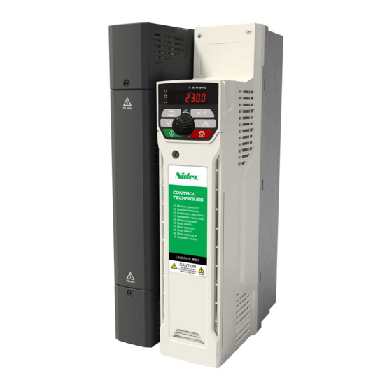
- Page 1 Control Quick Start Guide Unidrive M200/201 Flexible machine integration through communications Part Number: 0478-0282-03 Issue: 3...
- Page 2 Original Instructions For the purposes of compliance with the EU Machinery Directive 2006/42/EC This guide is intended to provide basic information required in order to set-up a drive to run a motor. For more detailed installation information, please refer to the relevant drive documentation which is available to download from: www.drive-setup.com Warnings, Cautions and Notes...
-
Page 3: Table Of Contents
Contents Safety information ..................4 Warnings, Cautions and Notes ................4 Installation and Use ....................4 Enclosure ......................... 4 Competence of the installer ..................4 Electric Shock and Fire Hazards ................5 Electrical installation ....................5 Setting up, commissioning and maintenance ............6 Safety of machinery, safety-critical applications ............ -
Page 4: Safety Information
Safety information Warnings, Cautions and Notes A Warning contains information which is essential for avoiding a safety hazard. WARNING A Caution contains information which is necessary for avoiding a risk of damage to the product or other equipment. CAUTION A Note contains information, which helps to ensure correct operation of the product. NOTE Installation and Use The information given in this publication is derived from tests and calculations on sample products. -
Page 5: Electric Shock And Fire Hazards
Electric Shock and Fire Hazards WARNING - Dangerous voltage Where products are supplied by or connected to mains voltages, the voltages used can cause severe electrical shock and/or burns, and could be lethal. Extreme care is necessary at all times when working with or adjacent to the equipment. Refer to the WARNING relevant documentation. -
Page 6: Setting Up, Commissioning And Maintenance
1.6.7 SELV terminals SELV terminals can be safely connected to other SELV equipment and further protection against human contact is not required. If an ELV terminal is connected directly to a SELV circuit (on the drive or other equipment), the combined circuit is ELV. -
Page 7: Electromagnetic Compatibility (Emc)
Electromagnetic compatibility (EMC) The product is designed to comply with international standards in a typical installation. Installation instructions are provided in the User Guide. If the installation is poorly designed or other equipment does not comply with international standards for EMC, the product might cause or suffer from disturbance due to electromagnetic interaction with other equipment. -
Page 8: Introduction
Introduction Unidrive M200/M201 delivers substantial communications and application integration through optional RS485 plus a wide range of industry standard fieldbus and I/O SI modules. Enhances machine up-time and performance with it’s remote control monitoring. Operating modes The drive is designed to operate in any of the following modes: 1. -
Page 9: Options
Options Table 3-1 System Integration (SI) option module identification Type Option module Color Name Further details Purple SI-PROFIBUS Medium SI-DeviceNet Grey Light Grey SI-CANopen Fieldbus Beige SI-Ethernet See relevant option module User Guide Brown Red SI-EtherCAT Yellow SI-PROFINET V2 Green Automation Orange SI-I/O... -
Page 10: Control Connections
Table 3-2 Adaptor Interface (AI) option module identification Type Option module Name AI-485 Adaptor Communications AI-485 24V Adaptor Backup AI-Backup Adaptor Backup AI-SMART Adaptor Control connections For information on the default control connections, refer to the back cover of this guide. The functionality of the control connections change depending on the setting of Pr 05. - Page 11 Figure 4-1 Pr 05 = AV Voltage speed reference input (AI 1) + 10 V output Voltage speed reference input (AI 2) Analog output 1 (motor frequency) + 24 V output Digital output (zero frequency) Drive enable Run forward Run reverse Analog input 1/ input 2 select Figure 4-2 Pr 05 = AI...
- Page 12 Figure 4-3 Pr 05 = AV.Pr Voltage speed reference input (AI 1) + 10 V output Reference select Analog output 1 (motor frequency) + 24 V output Digital output Terminal 5 Terminal 14 Reference selected (zero frequency) Analog reference 1* Drive enable Preset speed 2* Preset speed 3*...
- Page 13 Figure 4-5 Pr 05 = PrESEt Voltage speed reference input (AI 1) + 10 V output Reference select Analog output 1 (motor frequency) + 24 V output Digital output Terminal 5 Terminal 14 Reference selected (zero frequency) Preset speed 1* Drive enable Preset speed 2* Preset speed 3*...
- Page 14 Figure 4-7 Pr 05 = PAd.rEF Voltage speed reference input (AI 1) + 10 V output Voltage speed reference input (AI 2) Analog output 1 (motor frequency) + 24 V output Digital output (zero frequency) Drive enable Run forward Run reverse Analog input 1/ input 2 select Figure 4-8 Pr 05 = E.Pot...
- Page 15 Figure 4-9 Pr 05 = torquE Current speed reference Current speed input (AI 1) reference input + 10 V output Torque reference input (AI 2) When torque mode is selected and the drive is connected to an unloaded motor, the motor speed may increase rapidly to the WARNING maximum speed (Pr 02 +10 %)
-
Page 16: Keypad And Display
Keypad and display The keypad and display provide information to the user regarding the operating status of the drive, alarms and trip codes, and provide the means for changing parameters, stopping and starting the drive, and the ability to perform a drive reset. Figure 5-1 Unidrive M200 keypad detail Figure 5-2 Unidrive M201 keypad detail V A Hz rpm %... -
Page 17: Saving Parameters
Saving parameters When changing a parameter in Menu 0, the new value is saved when pressing the Enter button to return to parameter view mode from parameter edit mode. If parameters have been changed in the advanced menus, then the change will not be saved automatically. -
Page 18: Basic Parameters (Menu 0)
Basic parameters (Menu 0) Menu 0 is used to bring together various commonly used parameters for basic easy set up of the drive. Menu 0: Basic parameters Range Default Parameter Type RFC-A RFC-A Minimum Speed 0.00 to Pr 02 Hz 0.00 Hz RW Num Def.50: 50.00 Hz... - Page 19 Range Default Parameter Type RFC-A RFC-A NonE (0), rEAd (1), Prog (2), Parameter Cloning NonE (0) Auto (3), boot (4) CoASt (0), rP (1), CoASt (0), rP (1), rP.dc I (2), rP.dc I (2), Stop Mode dc I (3), td.dc I (4), dc I (3), rP (1) diS (5),...
- Page 20 Range Default Parameter Type RFC-A RFC-A Brake Controller Brake Apply Through 0.00 to 25.00 Hz 1.00 Hz RW Num Zero Threshold Brake Controller diS (0), rELAy (1), dig IO (2), diS (0) Enable USEr (3) Trip 0 0 to 255 ND NC PT PS Trip 1 0 to 255...
- Page 21 ** Setting Pr 07 to 0.0 will disable slip compensation. *** Following a rotating autotune, Pr 09 is continuously written to by the drive, calculated from the value of Stator Inductance (Pr 05.025). To manually enter a value into Pr 09, Pr 05.025 will need to be set to 0. Refer to the description of Pr 05.010 in the Parameter Reference Guide for further details.
- Page 22 Figure 6-1 Menu 0 logic diagram Analog Input 1/ Input 2 select Analog Input 1 Analog reference Analog Input Analog Input 1 1 Mode Analog Input 2 Analog Input 2 01.050 01.015 >1 Bipolar Reference Drive Enable Configuration Select Preset frequency reference Preset Reference 1 Preset Reference 2 Preset Reference 3...
- Page 23 RFC-A> FREQUENCY FORWARD REVERSE AT ZERO FREQUENCY Analog output Digital output Reference On Reverse Select Pre-ramp Final Demand Reference Reference Maximum Speed Ramp Enable Minimum Speed Motor parameters RFC-A mode only Rated Current Rated Speed x(-1) Rated Voltage Ramps Power Factor Catch A Spinning Motor RFC-A Speed-loop Rated Frequency...
-
Page 24: Unidrive M200/201 Parameter Descriptions
Unidrive M200/201 parameter descriptions Key: Read / Read Number Binary Text string Filtered Write only parameter parameter parameter Protected Rating Power-down default User save DE Destination copied parameter dependent save value Minimum Speed 0.00 to Pr 02 Hz 0.00 Hz RFC-A Set Pr 01 at the required minimum output frequency of the drive for both directions of rotation. - Page 25 Drive Configuration AV (0), AI (1), AV.Pr (2), AI.Pr (3), PrESEt (4), PAd (5), PAd.rEF (6), AV (0)* E.Pot (7), torquE (8), Pid (9) * With Unidrive M201, the default is PAd (5). Use Pr 05 to select the required frequency/speed reference as follows: Value Text Description...
- Page 26 Motor Rated Speed Def.50: 1500.0 rpm Def.60: 1800.0 rpm 0.0 to 33000.0 rpm Def.50: 1450.0 rpm RFC-A Def.60: 1750.0rpm Set to the rated speed of the motor (taken from the motor name plate). The motor rated speed is used to calculate the correct slip speed for the motor. Motor Rated Voltage 200V drive: 230 V 400V drive Def.50: 400 V...
- Page 27 Start/Stop Logic Select 0 to 6 RFC-A This parameter changes the functions of the input terminals which are normally associated with the enabling, starting and stopping the drive. Pr 11 Terminal 11 Terminal 12 Terminal 13 Latching Enable Run Forward Run Reverse /Stop Run Forward...
- Page 28 The table below gives all the possible analog input modes. Value Text Function 4-20.S Stop on loss 20-4.S Stop on loss 4-20.L 4-20 mA switching to equivalent of 4 mA input current on loss 20-4.L 20-4 mA switching to equivalent of 20 mA input current on loss 4-20.H 4-20 mA hold at level before loss on loss 20-4.H...
- Page 29 Status Mode Parameter 2 0.000 to 30.999 4.020 RFC-A This parameter and Status Mode Parameter 1 (Pr 23) define which parameters are displayed in Status mode. The values can be alternated by pressing the Escape key, if the drive is running. Status Mode Parameter 1 0.000 to 30.999 2.001...
- Page 30 Ramp Mode Select Fast (0), Std (1), Std.bst (2), Std (1) Fst.bst (3) RFC-A Defines the mode used by the ramp system. 0: Fast ramp 1: Standard ramp 2: Standard ramp with motor voltage boost 3: Fast ramp with motor voltage boost Fast ramp is linear deceleration at programmed rate, normally used when a braking resistor is installed.
- Page 31 Stop Mode CoASt (0), rP (1), rP.dc I (2), dc I (3), td.dc I (4), dis (5) rP (1) CoASt (0), rP (1), rP.dc I (2), RFC-A dc I (3), td.dc I (4), dis (5), No.rP (6) Defines how the motor is controlled when the run signal is removed from the drive. Value Text Description...
- Page 32 Pr 33 Text Function Disabled Enable Detect all frequencies Fr.Only Detect positive frequencies only Rv.Only Detect negative frequencies only Digital Input 5 Select Input (0), th.Sct (1), th (2), Input (0) th.Notr (3), Fr (4) RFC-A This parameter selects the function of Digital Input 5 (terminal 14). Value Text Function...
- Page 33 Digital Output 1 Control 0 to 21 RFC-A Defines the behaviour of digital output 1 (terminal 10). Value Description User defined by Digital IO1 Source/Destination A Drive running signal Frequency arrived signal Frequency level detection signal Frequency level detection signal Overload detection signal Power off state External fault stop...
- Page 34 Value Description User defined by Analog Output 1 Source A Frequency output Frequency reference Motor speed Current Magnitude Torque output Torque current output Voltage output DC bus voltage (0 to 800 V) Analog Input 1 Analog Input 2 Power output (0 to 2 x Pe) Torque limitation Torque reference (0 to 300 %) Maximum Switching Frequency...
- Page 35 Autotune 0 to 2 RFC-A 0 to 3 Defines the auto-tune test to be performed. There are two autotune tests available in open loop mode, a stationary and a rotating test. A rotating autotune should be used whenever possible so the measured value of power factor of the motor is used by the drive.
- Page 36 Control Mode Ur.S (0), Ur (1), Fd (2), Ur.Auto (3), Ur.I (4) Ur.I (4), SrE (5), Fd.tap (6) RFC-A Defines the drive output mode, which can either be a voltage mode or a current mode. Value Text Description Ur.S Stator resistance and voltage offset measured at each start No measurements Fixed boost mode.
- Page 37 Serial Address 1 to 247 RFC-A Used to define the unique address for the drive for the serial interface. The drive is always a slave, address 0 is used to globally address all slaves, and so this address should not be set in this parameter.
- Page 38 Brake Controller Brake Release Frequency 0.00 to 20.00 Hz 1.00 Hz RFC-A Defines the Brake Release Frequency. See Brake Controller Brake Release in Parameter Reference Guide. Brake Controller Brake Apply Frequency 0.00 to 20.00 Hz 2.00 Hz RFC-A Defines the Brake Apply Frequency. See Brake Controller Brake Release in Parameter Reference Guide.
- Page 39 Brake Controller Brake Apply Through Zero Threshold 0.00 to 25.00 Hz 1.00 Hz RFC-A Defines if the brake is applied through zero threshold. See Brake Controller Brake Release in Parameter Reference Guide. Brake Controller Enable diS (0), rELAy (1), dig IO (2), diS (0) USEr (3) RFC-A...
- Page 40 OUP Status -2147483648 to 2147483647 RFC-A This parameter indicates the status of the user program in the drive. For further information, refer to the Control User Guide. Frequency Controller Proportional Gain Kp1 RFC-A 0.000 to 200.000 s/rad 0.100 s/rad Defines the proportional gain for frequency controller 1. RFC modes only.
- Page 41 Spin Start Boost 0.0 to 10.0 RFC-A Spin Start Boost (Pr 69) is used by the algorithm that detects the frequency of a spinning motor when the drive is enabled and Catch A Spinning Motor (Pr 33) ≥ 1. For smaller motors the default value of 1.0 is suitable, but for larger motors, Spin Start Boost (Pr 69) may need to be increased.
- Page 42 PID1 Output Upper Limit 0.00 to 100.00 % 100.00 % RFC-A This parameter with PID1 Output Lower Limit (Pr 75) allows the output to be limited to a range. For further information, refer to the Parameter Reference Guide. PID1 Output Lower Limit ±100.00 % -100.00 % RFC-A...
- Page 43 User Drive Mode OPEn.LP (1) OPEn.LP (1), RFC-A (2) RFC-A RFC-A (2) Defines the mode of the drive. Reference Selected -Pr 02 to Pr 02 or Pr 01 to Pr 02 Hz RFC-A This is the basic reference selected from the available sources. Pre-ramp Reference -Pr 02 to Pr 02 or Pr 01 to Pr 02 Hz RFC-A...
- Page 44 Output Frequency ± 550.00 Hz RFC-A Open loop mode: The Output Frequency is the sum of the Post Ramp Reference and the motor slip compensation frequency. RFC-A mode: The output frequency is not controlled directly, but the Output Frequency is a measurement of the frequency applied to the motor.
- Page 45 Digital I/O Read Word 0 to 2047 RFC-A Digital I/O Read Word reflects the state of digital inputs/outputs 1 to 5 and the relay. Reference On Off (0) or On (1) RFC-A Reference On, which is controlled by the drive sequencer, indicates that the reference from the reference system is active.
-
Page 46: Running The Motor
Running the motor This section takes a new user through all the essential steps to running a motor for the first time. Table 7-1 Open Loop and RFC-A Action Detail Ensure: • The drive enable signal is not given, terminal 11 is open •... - Page 47 Action Detail Ready to run The drive is now ready to run the motor.Close the Run Forward or Run Reverse terminals on Unidrive M200; press keypad Start button on M201. Changing the selected Analog frequency reference (Speed Ref Increasing and Potentiometer on M201) will increase and decrease the speed decreasing speed of the motor.
-
Page 48: Diagnostics
Diagnostics Users must not attempt to repair a drive if it is faulty, nor carry out fault diagnosis other than through the use of the diagnostic features described in this chapter. If a drive is faulty, it must be returned to the supplier of the drive for repair. WARNING Table 8-1 Trip indications Trip... - Page 49 Trip Condition Description code Two or more parameters are The dESt trip indicates that destination output parameters of two dESt writing to the same destination or more logic functions (Menus 7 and 8) within the drive are parameter writing to the same parameter. dr.CF Drive configuration Contact the supplier of the drive.
- Page 50 Trip Condition Description code The instantaneous drive output current has exceeded.The set limit. Possible solutions: • Increase acceleration/deceleration rate Instantaneous output over current • If seen during autotune reduce the voltage boost OI.AC detected • Check for short circuit on the output cabling •...
- Page 51 Trip Condition Description code Control word watchdog has timed The control word has been enabled and has timed out Option module in option slot 1 has Option slot 1 on the drive is a different type to that installed SL.dF changed when parameters were last saved on the drive.
-
Page 52: Alarm Indications
Trip Condition Description code The U.S trip indicates that an error has been detected in the User Save error / not completed user save parameters saved in non-volatile memory. This trip can be initiated from within an onboard user program. UP.uS User Program trip Refer to the Control User Guide. -
Page 53: Nv Media Card Operation
NV Media Card Operation Figure 9-1 Installing the AI-Backup adaptor (SD Card) 1. Identify the two plastic fingers on the underside of the AI-Backup adaptor (1) - then insert the two fingers into the corresponding slots in the spring-loaded sliding cover on the top of the drive. 2. -
Page 54: Machine Control Studio
Machine Control Studio Machine Control Studio programming software powered by CODESYS Machine Control Studio software provides a flexible and intuitive environment for programming Unidrive M's new automation and motion control features. This new software offers programming for the Unidrive M200's onboard PLC (not available on Unidrive M201). Machine Control Studio is powered by CODESYS, the leading open software for programmable machine control. - Page 55 Figure 10-1 Frame 1 to 4 connections Quick start setup using default parameter settings Digital I/O Analog I/O 24 V user Analog input 1+ Digital I/O1 Frequency Zero frequency reference 1 10 V user Digital Input 2 Drive enable Digital input 3 Analog input 2 Frequency Run forward...
- Page 56 Figure 10-2 Frame 5 to 9 connections Quick start setup using default parameter settings Digital I/O Analog I/O 24 V user Analog input 1+ Digital I/O1 Frequency Zero frequency reference 1 10 V user Digital Input 2 Drive enable Digital input 3 Analog input 2 Frequency Run forward...