Table of Contents
Advertisement
Quick Links
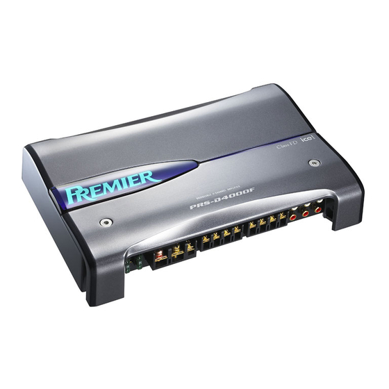
BRIDGEABLE FOUR-CHANNEL POWER AMPLIFIER
PRS-D4000F
PRS-D400
PRS-D4000F
PRS-D4000F
For details, refer to "Important Check Points for Good Servicing".
PIONEER CORPORATION
PIONEER ELECTRONICS (USA) INC. P.O. Box 1760, Long Beach, CA 90801-1760, U.S.A.
PIONEER EUROPE NV Haven 1087, Keetberglaan 1, 9120 Melsele, Belgium
PIONEER ELECTRONICS ASIACENTRE PTE. LTD. 253 Alexandra Road, #04-01, Singapore 159936
PIONEER CORPORATION 2006
/XU/EW5
4-1, Meguro 1-chome, Meguro-ku, Tokyo 153-8654, Japan
PRS-D4000F/XU/UC
/XU/ES
/XU/CN5
ORDER NO.
CRT3617
/XU/UC
K-ZZU. MAR. 2006 Printed in Japan
Advertisement
Table of Contents

Related Manuals for Pioneer PRS-D4000F/XU/UC


Summary of Contents for Pioneer PRS-D4000F/XU/UC
- Page 1 PIONEER CORPORATION 4-1, Meguro 1-chome, Meguro-ku, Tokyo 153-8654, Japan PIONEER ELECTRONICS (USA) INC. P.O. Box 1760, Long Beach, CA 90801-1760, U.S.A. PIONEER EUROPE NV Haven 1087, Keetberglaan 1, 9120 Melsele, Belgium PIONEER ELECTRONICS ASIACENTRE PTE. LTD. 253 Alexandra Road, #04-01, Singapore 159936 PIONEER CORPORATION 2006 K-ZZU.
-
Page 2: Safety Information
• Be careful in handling ICs. Some ICs such as MOS type are so fragile that they can be damaged by electrostatic induction. PRS-D4000F/XU/UC... - Page 3 To protect products from damages or failures during transit, the shipping mode should be set or the shipping screws should be installed before shipment. Please be sure to follow this method especially if it is specified in this manual. PRS-D4000F/XU/UC...
-
Page 4: Table Of Contents
5. ELECTRICAL PARTS LIST ..........................22 6. ADJUSTMENT ............................... 29 7. GENERAL INFORMATION ..........................30 7.1 DIAGNOSIS ............................. 30 7.1.1 DISASSEMBLY ............................. 30 7.1.2 CONNECTOR FUNCTION DESCRIPTION ..................31 7.2 IC ................................32 7.3 PRODUCT DESCRIPTION........................35 8. OPERATIONS ..............................36 PRS-D4000F/XU/UC... -
Page 5: Specifications
1. SPECIFICATIONS PRS-D4000F/XU/UC... -
Page 6: Exploded Views And Parts List
• Screw adjacent to mark on the product are used for disassembly. • For the applying amount of lubricants or glue, follow the instructions in this manual. (In the case of no amount instructions,apply as you think it appropriate.) 2.1 PACKING PRS-D4000F/XU/UC... - Page 7 See Contrast table(2) 5-4 Warranty Card See Contrast table(2) Shaft YLP5001 Cord Assy YDE5010 (2) CONTRAST TABLE PRS-D4000F/XU/UC , PRS-D400/XU/EW5 , PRS-D4000F/XU/ES and PRS-D4000F/XU/CN5 are constructed the same except for the following: Mark Description PRS-D4000F/XU/UC PRS-D400/XU/EW5 PRS-D4000F/XU/ES PRS-D4000F/XU/CN5 Owner's Manual...
-
Page 8: Exterior
2.2 EXTERIOR PRS-D4000F/XU/UC... - Page 9 Terminal(CN607) VNF1084 LED(D604) NSPB346BS Cushion YNN5001 Terminal(CN608) VNF1084 Terminal(CN821) VNF1084 (2) CONTRAST TABLE PRS-D4000F/XU/UC , PRS-D400/XU/EW5 , PRS-D4000F/XU/ES and PRS-D4000F/XU/CN5 are constructed the same except for the following: Mark Description PRS-D4000F/XU/UC PRS-D400/XU/EW5 PRS-D4000F/XU/ES PRS-D4000F/XU/CN5 Heat Sink YNR5012 YNR5006 YNR5020 YNR5020...
-
Page 10: Block Diagram And Schematic Diagram
Detailed page 18.32dBs(RCA IN) 6.2dBs(SP IN) GAIN CONTROL INPUT 18.5dBs(MAX)(SP IN) 18.5dBs(MAX)(RCA IN) CUT OFF FREQUENCY CONTROL CCH1543 INPUT C831 SELECT 18.32dBs(RCA IN) 6.2dBs(SP IN) C834 CCH1543 GAIN CONTROL INPUT CUT OFF FREQUENCY CONTROL LPF/HPF CCH1543 C833 LED PCB PRS-D4000F/XU/UC... - Page 11 No differentiation is made between chip capacitors and discrete capacitors. > > POWER TERMINALS The > mark found on some component parts indicates the importance of the safety factor of the part. Therefore, when replacing, be sure to use parts of identical designation. PRS-D4000F/XU/UC...
- Page 12 RCA/SPEAKER INPUT PRS-D4000F/XU/UC...
- Page 13 PRS-D4000F/XU/UC...
- Page 14 PRS-D4000F/XU/UC...
- Page 15 PRS-D4000F/XU/UC...
-
Page 16: Pcb Connection Diagram
1.The parts mounted on this PCB include all necessary parts for several destination. SIDE A For further information for respective destinations, be sure to check with the schematic dia- gram. SIDE B P.C.Board Chip Part RY501 CN601 CN301 SPEAKER POWER TERMINALS PRS-D4000F/XU/UC... - Page 17 SIDE A AMP PCB L501 L502 L503 L504 CN858 CN859 RY501 RY502 CN851 CN302 SPEAKER OUTPUT SPEAKER OUTPUT CN860 CN861 PRS-D4000F/XU/UC...
- Page 18 AMP PCB IC321 IC322 PRS-D4000F/XU/UC...
- Page 19 SIDE B IC602 CN609 CN610 PRS-D4000F/XU/UC...
-
Page 20: Sw Pcb
4.2 SW PCB SW PCB SW PCB SIDE A SIDE B CN861 CN859 CN860 CN858 PRS-D4000F/XU/UC... -
Page 21: Led Pcb
4.3 LED PCB LED PCB LED PCB SIDE A SIDE B CN609 CN610 PRS-D4000F/XU/UC... -
Page 22: Electrical Parts List
IC 851 (B,181,52) IC NJM2068MD Q 632 (A,95,168) Transistor 2SD2395 IC 852 (B,222,52) IC NJM2068MD Q 633 (A,81,168) Transistor 2SB1566 IC 853 (B,270,37) IC NJM2068MD Q 634 (A,108,168) Transistor 2SD2395 IC 854 (B,287,37) IC NJM2068MD IC 902 (B,113,144) IC NJM78M05DL1A PRS-D4000F/XU/UC... - Page 23 R 211 (B,141,51) RS1/16S103J RY501 (A,143,38) Relay YSR5002 R 212 (B,141,53) RS1/16S102J RY502 (A,203,38) Relay YSR5002 R 213 (B,141,56) RS1/16S224J TH601 (A,216,166) Thermistor CCX1013 R 301 (B,306,45) RS1/16S222J TH602 (A,13,78) Thermistor CCX1013 R 302 (B,308,42) RS1/16S222J TH603 (A,81,61) Thermistor CCX1064 PRS-D4000F/XU/UC...
- Page 24 R 358 (B,246,96) RS1/16S102J R 542 (B,191,96) RS1/16S103J R 359 (B,186,96) RS1/16S682J R 543 (B,239,89) RS1/16S103J R 360 (B,243,96) RS1/16S682J R 544 (B,248,96) RS1/16S103J R 363 (B,188,73) RS1/16S473J R 545 (A,153,110) RS2LMF100J R 364 (B,205,90) RS1/16S473J R 546 (A,209,110) RS2LMF100J PRS-D4000F/XU/UC...
- Page 25 R 660 (A,65,114) RS1/2PMF220J C 101 (B,314,40) CCSRCH470J50 R 661 (A,51,111) RS1/2PMF220J C 102 (B,314,71) CCSRCH470J50 R 662 (A,84,104) RS1/2PMF220J C 103 (B,314,126) CCSRCH470J50 R 665 (A,87,161) RS1/2PMF100J C 104 (B,314,157) CCSRCH470J50 R 666 (A,104,160) RS1/2PMF100J C 105 (A,324,33) CFTNA154J50 PRS-D4000F/XU/UC...
- Page 26 C 334 (B,272,84) CKSRYB104K50 C 526 (B,189,154) CKSQYF105Z50 C 335 (A,208,81) CEAT4R7M50 C 527 (B,247,160) CKSQYF105Z50 C 336 (A,265,81) CEAT4R7M50 C 528 (B,259,154) CKSQYF105Z50 C 337 (A,215,86) CEAT4R7M50 C 535 (B,171,156) CKSQYF105Z50 C 338 (A,272,86) CEAT4R7M50 C 536 (B,182,162) CKSQYF105Z50 PRS-D4000F/XU/UC...
- Page 27 (A,109,155) 22 µF/ 35 V YCH5008 C 611 (A,123,42) CEAT471M16 C 697 (A,87,150) 22 µF/ 35 V YCH5008 C 612 (B,97,41) CKSRYB103K50 C 811 (B,244,27) CKSQYB102K50 C 613 (A,106,49) CEAT220M25 C 812 (B,233,28) CKSQYB102K50 C 614 (B,232,78) CKSRYB104K50 C 813 (B,270,25) CKSQYB102K50 PRS-D4000F/XU/UC...
- Page 28 C 881 (B,184,59) CKSRYB103K50 C 882 (B,226,58) CKSRYB103K50 C 883 (B,266,37) CKSRYB103K50 C 884 (B,283,38) CKSRYB103K50 C 885 (B,177,49) CKSRYB103K50 C 886 (B,218,50) CKSRYB103K50 C 887 (B,275,40) CKSRYB103K50 C 888 (B,293,41) CKSRYB103K50 C 951 (A,139,83) CEANP221M16 C 953 (B,133,65) CKSRYB473K50 PRS-D4000F/XU/UC...
-
Page 29: Adjustment
6. ADJUSTMENT There is no information to be shown in this chapter. PRS-D4000F/XU/UC... -
Page 30: General Information
Remove the two screws. Remove the five screws and then remove the Case. Case Fig.1 Removing the Amp Unit (Fig.2) Remove the six screws. Remove the nine screws. Disconnect the connector and then remove the Amp Unit. Amp Unit Fig.2 PRS-D4000F/XU/UC... -
Page 31: Connector Function Description
7.1.2 CONNECTOR FUNCTION DESCRIPTION PRS-D4000F/XU/UC... - Page 32 - Block Diagram Receiver, Control Comparator clip control and DC servo Local protection VD/VS Thermal Protection Vdd/Vss Check Local disable Voltage (Global And current Protect.) Reference Local protection Receiver, clip control Control Comparator and DC servo - Pin Layout PRS-D4000F/XU/UC...
- Page 33 ICC3 - Block Diagram - Pin Layout High side section Current protection detection High side Receiver protection Receiver, Pulse safestart generator Current & Enable detection Levelshift decoding Minimum Blanking pulse Delay Delay PRS-D4000F/XU/UC...
- Page 34 NJM78M05DL1A 3 OUT 2 GND 1 IN NJM79M05DL1A 3 OUT 2 IN 1 COMMON PRS-D4000F/XU/UC...
-
Page 35: Product Description
However, with this amplifier, the circuit that controls On/Off of amplifier by detecting DC element of SP output line of OEM product is mounted. This is called "Input Sensor". Therefore, if there is a DC element in SP output, the Input Sensor functions. PRS-D4000F/XU/UC... -
Page 36: Operations
8. OPERATIONS PRS-D4000F/XU/UC... - Page 37 PRS-D4000F/XU/UC...