Table of Contents
Advertisement
Quick Links
Installation Manual
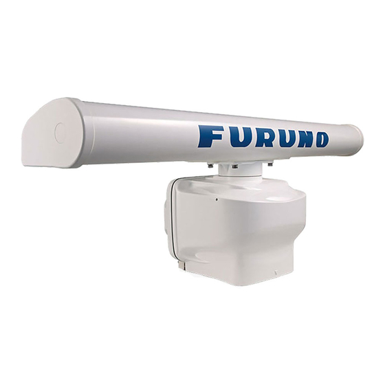
RADAR SENSOR
DRS6A X-Class/DRS12A X-Class/DRS25A X-Class
Model
SAFETY INSTRUCTIONS ................................................................................................ i
SYSTEM CONFIGURATION .......................................................................................... iii
EQUIPMENT LISTS........................................................................................................ iv
1. INSTALLATION AND WIRING................................................................................... 1
1.1 Mounting Considerations ......................................................................................................1
1.2 Included Items.......................................................................................................................3
1.3 Required Tools and Materials ...............................................................................................4
1.4 Fastening the Radiator to the Radiator Bracket....................................................................5
1.5 Mounting the Antenna Unit ...................................................................................................7
1.6 Wiring..................................................................................................................................10
2. INITIAL SETUP......................................................................................................... 15
2.1 Initial Setup for TZT9/TZT14/TZTBB ..................................................................................16
2.2 Initial Setup for TZTL12F/TZTL15F ....................................................................................18
3. MAINTENANCE, TROUBLE SHOOTING ................................................................ 23
3.1 Maintenance .......................................................................................................................24
3.2 Troubleshooting ..................................................................................................................25
3.3 Replacement of Fuse..........................................................................................................25
3.4 Life of Parts.........................................................................................................................26
APPENDIX 1 RADIO REGULATORY INFORMATION ............................................AP-1
SPECIFICATIONS ..................................................................................................... SP-1
PACKING LISTS ......................................................................................................... A-1
OUTLINE DRAWINGS ................................................................................................ D-1
INTERCONNECTION DIAGRAM ................................................................................ S-1
www.furuno.com
All brand and product names are trademarks, registered trademarks or service marks of their respective holders.
Advertisement
Table of Contents
Troubleshooting

Related Manuals for Furuno DRS12A X-Class


Summary of Contents for Furuno DRS12A X-Class
-
Page 1: Table Of Contents
Installation Manual RADAR SENSOR DRS6A X-Class/DRS12A X-Class/DRS25A X-Class Model SAFETY INSTRUCTIONS ....................i SYSTEM CONFIGURATION ..................iii EQUIPMENT LISTS......................iv 1. INSTALLATION AND WIRING................... 1 1.1 Mounting Considerations ......................1 1.2 Included Items........................3 1.3 Required Tools and Materials ....................4 1.4 Fastening the Radiator to the Radiator Bracket..............5 1.5 Mounting the Antenna Unit ....................7... -
Page 3: Safety Instructions
SAFETY INSTRUCTIONS The installer of the equipment must read the safety instructions before attempting to install the equipment. Indicates a potentially hazardous situation which, if not avoided, WARNING could result in death or serious injury. Indicates a potentially hazardous situation which, if not avoided, CAUTION can result in minor or moderate injury. - Page 4 - Name: FURUNO (UK) LTD. - Address: West Building Penner Road Havant Hampshire PO9 1QY, U.K. Program No. • 0359355-01.** ** denotes minor modifications. CE declaration With regards to CE declarations, please refer to our website (www.furuno.com), for further information about RoHS conformity declarations.
-
Page 5: System Configuration
Multi Function Display NavNet TZtouch/Navnet TZtouch 2 NavNet TZtouch/Navnet TZtouch 2 This radar series is compatible with the FURUNO Multi Function Displays and software version combinations shown below. The combination with other models may not operate properly. • DRS6A X-Class TZT9, TZT14 and TZTBB: Version 4.21 or later... -
Page 6: Equipment Lists
EQUIPMENT LISTS Standard supply Name Type Code No. Remarks Scanner Unit RSB-134-112 For DRS6A X-Class RSB-134-113 For DRS12A X-Class RSB-134-114 For DRS25A X-Class Radiator XN10A* 3.4 ft XN12A 4 ft XN13A 6 ft Installation CP03-37101 001-426-290 For scanner unit Materials... -
Page 7: Installation And Wiring
INSTALLATION AND WIRING NOTICE Do not apply paint, anti-corrosive sealant or contact spray to coating or plastic parts of the equipment. Those items contain organic solvents that can damage coating and plastic parts, especially plastic connectors. Mounting Considerations Select a mounting location, keeping in mind the following points: •... - Page 8 Not recommended • Setup the antenna unit position on the FURUNO Multi Function Display after install- ing the unit, referring to the chapter 2. If the antenna unit position is not setup cor- rectly, the radar echoes on the display may not be aligned with the actual target’s...
-
Page 9: Included Items
• Documents (1 set): 10 A: For DRS12A/25A X-Class 15 A: Not used. Cable assembly Supplied for DRS12A X-Class and DRS25A X-Class • Cable assembly* (1 pcs): • Fuse for replacement** • Label** (3 pcs) • How to Replace the Fuse... -
Page 10: Required Tools And Materials
1. INSTALLATION AND WIRING Required Tools and Materials The following tools should be prepared in advance for this installation. Name Remarks Electrical drill For making the mounting holes, drill bit: 15 mm Phillips-head screw driver #3, for securing the cable cover Wrench For M8 (Hex. -
Page 11: Fastening The Radiator To The Radiator Bracket
1. INSTALLATION AND WIRING Fastening the Radiator to the Radiator Bracket 1. Remove the radiator cap from the radiator bracket. Radiator bracket Radiator cap 2. Apply adhesive to the surface of the radiator bracket as shown in the figure below. Top view: Scanner unit Adhesive 10 mm... - Page 12 1. INSTALLATION AND WIRING 4. Apply adhesive to the thread holes on the bottom of the radiator (4 locations). Adhesive Bottom view: Radiator 5. Prepare four bolt assemblies; pass the spring washer (M8) and flat washer (M8) through the each hex bolt (M8 30) then apply adhesive. Flat washer Adhesive Spring washer...
-
Page 13: Mounting The Antenna Unit
1. INSTALLATION AND WIRING 7. Apply adhesive to the holes and bolts at the locations indicated with arrows in the figure below. Also apply adhesive to the junction between the radiator and the ra- diator bracket. Bolt assembly - side view (detailed) Radiator Apply adhesive to the Apply adhesive to the... - Page 14 1. INSTALLATION AND WIRING Detailed view Vent hole: Do NOT cover this hole. Adhesive Adhesive Stud bolt Stud bolt NOTICE Do not fasten stud bolts tightly after the bolts contact with the bottom of the threaded holes. If the bolts are fastened excessively, the chassis bottom may be damaged which can result in malfunction.
- Page 15 1. INSTALLATION AND WIRING 6. Hoist the antenna unit to the installation location, using two belt slings. Note: When you hoist the antenna unit. keep in mind the following points: • When you hoist the antenna unit, set two belt slings to the radiator bracket. Do not set the belt slings to the radiator, the radiator may get damaged.
-
Page 16: Wiring
For details, see “How to Replace the Fuse” (C32- 01604). • For DRS12A X-Class and DRS25A X-Class, insert the 10 A fuse in the fuse hold- er. Also, attach the supplied fuse rating label to the fuse holder. For details, see “How to Replace the Fuse”... - Page 17 1. INSTALLATION AND WIRING 1. Unfasten two screws, circled in the following figure, to remove the cable cover. Cable cover Cable cover 2. Connect the cable assembly (supplied) to the power/LAN cable that is pre-at- tached to the antenna unit. 3.
- Page 18 Cable cover - bottom view 8. Reattach the cable cover. 9. Connect the LAN connector of the cable assembly to a LAN port on the FURUNO Multi Function Display or Ethernet HUB. Note 1: Do not connect the LAN connector to on-board LAN.
- Page 19 Ethernet HUB Cable assembly LAN connector FURUNO Multi Function Display Note 2: When LAN cable extension is needed, use the optional LAN cable (MOD- Z072) and joint box (TL-CAT-012). After connection is completed, wrap the con- nector with vinyl tape to waterproof the LAN connector.
- Page 20 1. INSTALLATION AND WIRING...
-
Page 21: Initial Setup
TZT9, TZT14 and TZTBB: Version 5.01 or later (Planned release: End of 2016) TZTL12F and TZTL15F: Version 4.01 or later (Planned release: End of 2016) Turn on the antenna unit and FURUNO Multi Function Display. Initial setup for this an- tenna must be done on the FURUNO Multi Function Display. -
Page 22: Initial Setup For Tzt9/Tzt14/Tztbb
2. INITIAL SETUP Initial Setup for TZT9/TZT14/TZTBB 1. Press the Home key (or tap the Home icon). 2. Select [Menu] on the menu icon bar to open the main menu. 3. Select [Radar]. 4. Select [Radar Source] on the [Menu Radar] sub menus, then select the radar type connected. - Page 23 2. INITIAL SETUP Menu item Description [Antenna Longitudinal Po- Referring to the figure on the right, enter sition] the radar antenna positioning bow-stern Origin (Longitudinal) and port-starboard (Lateral) [Antenna Lateral Position (- position from the origin. Port)] [Auto Tuning] Enable/disable auto tuning for the connected radar. [Tuning Source] For dual-range display, select the range to use as the manual tuning source.
-
Page 24: Initial Setup For Tztl12F/Tztl15F
2. INITIAL SETUP 1. Select a range between 0.125 and 0.25 NM and set the mode to “head up“. You can select a range by a pinch action. The range and range ring interval ap- pear at the bottom left of the screen. Range Range ring interval Zoom in... - Page 25 2. INITIAL SETUP 5. Referring to the tables below, set up the radar. [Radar] menu - [Radar Initial Setup] Menu item Description [Antenna Rotation] Select the antenna rotation speed. [Antenna Heading Align] See "How to align the antenna heading" on page 20. [Main Bang Suppression] If main bang appears at the screen center, slide the circle icon so that the main bang disappears, while watching the...
- Page 26 2. INITIAL SETUP How to align the antenna heading You have mounted the antenna unit facing straight ahead in the direction of the bow. Therefore, a small but conspicuous target dead ahead visually should appear on the heading line (zero degrees). You may observe a minor bearing error on the display.
- Page 27 2. INITIAL SETUP 2. Turn the vessel’s bow toward a target. 3. Tap the [Home] icon to show the home screen and display mode settings. 4. Tap [Radar] to show the [Radar] menu. 5. Drag the [Radar] menu to show the [RADAR INITIAL SETUP] menu. 6.
- Page 28 2. INITIAL SETUP This page is intentionally left blank.
-
Page 29: Maintenance, Trouble Shooting
MAINTENANCE, TROUBLE SHOOTING Periodic checks and maintenance are important for proper operation of any electronic system. This chapter contains maintenance and troubleshooting instructions to be fol- lowed to obtain optimum performance and the longest possible life of the equipment. Before attempting any maintenance or troubleshooting procedure please review the safety information below and at the front of this manual. -
Page 30: Maintenance
3. MAINTENANCE, TROUBLE SHOOTING Maintenance Regular maintenance is important for good performance. Check the points mentioned below every 3 to 6 months to keep the antenna unit in good working order. Check point Action Remedy, remarks Check points every 3 to 6 months Cable Check that all cables are firmly •... -
Page 31: Troubleshooting
3. MAINTENANCE, TROUBLE SHOOTING Troubleshooting The table below provides simple troubleshooting procedures to restore normal opera- tion. If you cannot restore normal operation, contact your dealer for advice. Problem Remedy The multi function display can- • Check that all cables are tightly fastened. not control the radar. -
Page 32: Life Of Parts
MAF1422B 000-158-788-12 5,000 hours For DRS6A X-Class FNE1201 001-245-890 5,000 hours For DRS12A X-Class MG5436 000-140-762-13 5,000 hours For DRS25A X-Class Antenna Motor When an antenna motor reaches the end of its life, the antenna’s rotation may stop or abnormal noise sounds from the antenna unit. If such symptom occurs, contact your dealer about replacement of the antenna motor. - Page 33 Relative wind load 70 kn or less RADAR FUNCTION Tx frequency 9410 ±30 MHz Output power DRS6A X-Class 6 kW nominal DRS12A X-Class 12 kW nominal DRS25A X-Class 25 kW nominal Duplexer Ferrite circulator with diode limiter Intermediate frequency 60 MHz...
- Page 34 FURUNO DRS6A/12A/25A X-Class POWER SUPPLY DRS6A X-Class 24 VDC (21.6-31.2 VDC): 4.0 A DRS12A X-Class 24 VDC (21.6-31.2 VDC): 4.5 A DRS25A X-Class 24 VDC (21.6-31.2 VDC): 5.6 A ENVIRONMENTAL CONDITIONS Ambient temperature -25°C to +55°C (storage: -30°C to +70°C) Relative humidity 95% or less at +40°C...
-
Page 35: Appendix 1 Radio Regulatory Information
êolé et respecte les règles d'exposition aux fréquences radioélectriques (RF) CNR-102 de l'IC. Cet équipement doit etre installé et utilise en gardant une distance de 300 cm (DRS6A X-Class (RTR-112)), 310 cm (DRS12A X-Class (RTR-113)), 770 cm (DRS25A X-Class (RTR-114)) ou plus entre le dispositif rayonnant et le corps. - Page 44 When a claim is made, FURUNO has a right to choose whether with other electronic devices. The imported product may also be to repair the product or replace it.
- Page 45 24 months from installation date provided the work is done by Furuno U.S.A., Inc. or an AUTHORIZED Furuno dealer during normal shop hours and within a radius of 50 miles of the shop location.
- Page 46 Цялостният текст на EC/UK декларацията за съответствие може да се намери на следния интернет адрес: Spanish Por la presente, Furuno Electric Co., Ltd. declara que el tipo de equipo radioeléctrico arriba mencionado es conforme con la Directiva 2014/53/UE, SI 2017/1206. (ES) El texto completo de la declaración de conformidad de la EU/UK está...
- Page 47 Lithuanian Aš, Furuno Electric Co., Ltd., patvirtinu, kad pirmiau minėta radijo įrenginių tipas (LT) atitinka Direktyvą 2014/53/ES, SI 2017/1206. Visas ES/JK atitikties deklaracijos tekstas prieinamas šiuo interneto adresu: Hungarian Furuno Electric Co., Ltd. igazolja, hogy fent említett típusú rádióberendezés (HU) megfelel a 2014/53/EU, SI 2017/1206 irányelvnek.
- Page 48 The paper used in this manual is elemental chlorine free. ・FURUNO Authorized Distributor/Dealer 9-52 Ashihara-cho, Nishinomiya, 662-8580, JAPAN A : DEC 2015 Printed in Japan All rights reserved. E3 : APR . 07, 2021 Pub. No. IME-36460-E3 (YOTA ) DRS6A_X-Class...