
Related Manuals for Icom IC-F6121D


Summary of Contents for Icom IC-F6121D
- Page 1 Limited functions only Limited functions only INSTRUCTION MANUAL VHF MOBILE TRANSCEIVERS iF5120D Series UHF MOBILE TRANSCEIVERS iF6120D Series...
-
Page 2: Explicit Definitions
• Consult the dealer or an experienced radio/TV technician for help. Icom, Icom Inc. and the Icom logo are registered trademarks of Icom Incor- porated (Japan) in Japan, the United States, the United Kingdom, Germany, France, Spain, Russia and/or other countries. -
Page 3: Precautions
Approved Icom optional equipment is designed for optimal different pin assignments and may damage the transceiver. performance when used with an Icom transceiver. Icom is not responsible for the destruction or damage to an DO NOT use or place the transceiver in areas with tem- Icom transceiver in the event the Icom transceiver is used peratures below –30°C (–22°F) or above +60°C (+140°F), or... -
Page 4: Table Of Contents
TABLE OF CONTENTS IMPORTANT ................i 3 CONNECTION AND MAINTENANCE ....14–16 EXPLICIT DEFINITIONS ............i ■ Rear panel connection ..........14 FCC INFORMATION ............. i ■ Supplied Accessories ..........15 PRECAUTIONS ..............ii ■ Mounting the transceiver ..........15 TABLE OF CONTENTS ............iii ■... -
Page 5: Anel Descri.tion .Anel Descri.tion
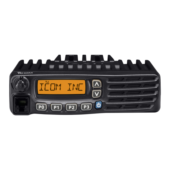
.ANEL DESCRI.TION ■ Front panel Function display (p. 2) Speaker q AF VOLUME CONTROL KNOB [VOL] t MICRO.HONE CONNECTOR Rotate the knob to adjust the desired audio output level. Connect the supplied or optional microphone. • Minimum audio level is pre-set. (p. 11) NEVER connect non-specified microphones. -
Page 6: Function Display
PANEL DESCRIPTION ■ Function display y ENCRY.TION ICON Appears when the encryption function is activated while operating in the digital mode. u BELL ICON Appears/blinks when the specific 2/5-tone/MDC* code is received, according to the pre-programming. i SCAN ICON Blinks during scan. q TRANSMIT ICON o AL.HANUMERIC DIS.LAY Appears while transmitting. -
Page 7: Programmable Function Keys
[.0], [.1], [.2] and [.3] programmable function keys. • When Power ON Scan function is activated, push to pause Consult your Icom dealer or system operator for details con- the scanning operation. And the paused scan restarts after the cerning your transceivers programming. - Page 8 PANEL DESCRIPTION PRIO A/B KEYS LOCK KEY ➥ Push to select Priority A or Priority B channel. Hold down to electronically lock all programmable keys ex- ➥ Hold down [.rio A (Rewrite)] or [.rio B (Rewrite)] for 1 cept the following: [Moni(Audi)], [Lock], [Call] (incl.
- Page 9 PANEL DESCRIPTION WIDE/NARROW KEY EMERGENCY KEY Push to toggle the IF bandwidth between wide and narrow. Hold down this for specified period to transmit an emergency • The wide passband width can be selected from 25.0 or 20.0 kHz call. using the CS-F3100D/F5120D .
- Page 10 PANEL DESCRIPTION TX CODE CHANNEL SELECT KEY USER SET MODE KEY ➥ Push to enter the TX code channel selection mode. Then ➥ Hold down for 1 sec. to enter user set mode. set the desired channel using [CH Up]/[CH Down]. (p. 9) •...
-
Page 11: Basic O.eration Basic O.eration
BASIC O.ERATION ■ Turning power ON ■ Channel selection q Push [ ] to turn the power ON. Several types of channel selections are available. Methods w If the transceiver is programmed for a start up password, may differ according to your system set up. input the digit codes as directed by your dealer. -
Page 12: Call Procedure
BASIC OPERATION ■ Call procedure ■ Receiving and transmitting Receiving: When your system employs tone signaling (excluding CTCSS and DTCS), a call procedure may be necessary prior to voice q Hold down [ ] for 1 sec. to turn the power ON. w Push [CH Up] or [CH Down] to select a channel, in se- transmission. - Page 13 BASIC OPERATION D Transmitting notes D TX code channel selection • Transmit inhibit function If the transceiver has [TX Code CH Select] assigned to it, The transceiver has several inhibit functions which restrict the indication can be toggled between the operating channel transmission under the following conditions: number (or name) and TX code channel number (or name).
- Page 14 BASIC OPERATION D TX code number edit USING [TX CODE ENTER] KEY: (PMR operation only) q Push [TX Code Enter] to enter the TX code edit mode. If the transceiver has [TX Code CH Select] or [TX Code • The digit to be edited blinks. Enter] assigned to it, TX code contents can be edited within w Push [TX Code Enter] to select the desired digit to be the allowable digits.
-
Page 15: User Set Mode
BASIC OPERATION ■ User set mode User set mode can be accessed with ‘Power ON’ function. In this case, all set mode items are available. e Push [.0] several times to select the appropriate item. User set mode allows you to set seldom-changed settings Then, push [Up] or [Down] to set the desired level/condi- and you can “customize”... -
Page 16: Scrambler Function
BASIC OPERATION ■ Encryption function ■ Stun function The encryption function provides private communication be- When the specified ID, set as a stun ID or kill ID, is received, tween stations while operating in the digital mode. the stun function is activated. When the stun ID is received, the transceiver becomes unus- q Push [Encryption] to turn the encryption function ON. -
Page 17: Mdc 1200 System Operation
Emergency MDC 1200 system command once or repeat- An additional feature of MDC 1200 system found in Icom edly for a programmed number of times until it receives the transceivers is called aliasing. Each transceiver on the system acknowledgement signal. -
Page 18: Connection And Maintenance
CONNECTION AND MAINTENANCE ■ Rear panel connection q ANTENNA CONNECTOR e MICRO.HONE HANGER Antenna Connects to an antenna. Contact Connect the supplied micro- phone hanger to the vehicle’s your dealer about antenna selec- tion and placement. ground for microphone on/off hook functions. -
Page 19: Supplied Accessories
CONNECTION AND MAINTENANCE ■ Supplied Accessories ■ Mounting the transceiver The universal mounting bracket supplied with your trans- Microphone Microphone hanger Microphone ceiver allows overhead mounting. and screw set hanger cable • Mount the transceiver securely with the 4 supplied screws to a thick surface which can support more than 1.5 kg (3.3 lb). -
Page 20: Antenna
CONNECTION AND MAINTENANCE ■ Antenna ■ Options A key element in the performance of any communication sys- • O.C-1132A/O.C-347 dc power cable tems is an antenna. Contact your dealer for more information 2 fuse holders are attached. USE the 20 A fuse only. regarding antennas and how to install them. -
Page 21: Safety Training Information
SAFETY TRAINING INFORMATION 3. IC-F5121D: Your Icom radio generates RF electromagnetic en- Transmit only when people outside the vehicle are at least the ergy during transmit mode. This radio is designed recommended minimum distance of 100 centimeters away from for and classified as “Occupational Use Only”, the properly installed antenna. - Page 22 LCD. You can cause the radio to transmit by pressing the “PTT” switch. Electromagnetic Interference/Compatibility During transmissions, your Icom radio generates RF energy that can possibly cause interference with other devices or systems. To avoid such interference, turn off the radio in areas where signs are posted to do so.
- Page 23 MEMO...
- Page 24 A-6xxxX-1EX Printed in Japan © 2010 Icom Inc. 1-1-32 Kamiminami, Hirano-ku, Osaka 547-0003, Japan Printed on recycled paper with soy ink.