
Related Manuals for Omega HH520


Summary of Contents for Omega HH520
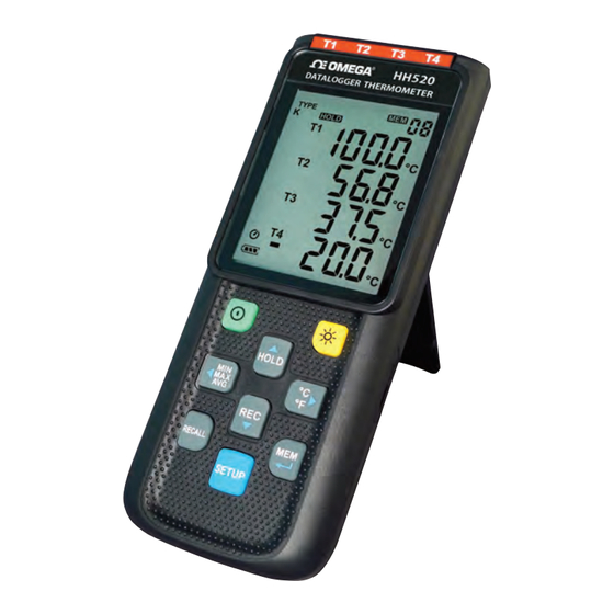
- Page 1 User’ s Gui d e Shop online at omega.com e-mail: info@omega.com For latest product manuals: www.omegamanual.info NORWALK, CT HH520 4 Channel ype J, K, T, E Data Logger Thermometer...
- Page 2 Fax: (203) 359-7700 e-mail: info@omega.com For Other Locations Visit omega.com/worldwide The information contained in this document is believed to be correct, but OMEGA accepts no liability for any errors it contains, and reserves the right to alter specifications without notice.
-
Page 3: Table Of Contents
7.3.5 Set T1-T2 subtraction mode.………………...…........9 7.3.6 Set auto power off time.…………..……………….………......9 7.3.7 Set system clock.………………………….………........9 7.4 Clearing Data Logger Records.……..………………........10 7.5 Clearing Instant Read-out Memory.…..…………….………......10 7.6 Connecting To A computer.…………….….…………........10 8. Power Preparation………………………………………………………………...10 8.1 Battery Replacement……………………………………………………….....10 9. Testlink HH520 Software………………………………………….…….....11 10. Maintenance.….….……………………………………………………………...…..…17... -
Page 4: General Description
DATALOGGER THERMOMETER 1. GENERAL DESCRIPTION Thank you for choosing our data logger thermometer. To ensure the safety and the best performance of this instrument, we recommend you to read and follow the manual carefully before operation. Data can be stored in the meter or directly saved on a computer through PC interface. Recorded data can be further processed by PC computer. -
Page 5: Specifications
DATALOGGER THERMOMETER 4. SPECIFICATIONS Measurement range: K: -200°C ~1372°C (- 328°F ~ 2501°F) J: -200°C~1000°C (- 328°F ~ 1832°F) E: -200°C~750°C (- 328°F ~ 1382°F) T: -200°C~400°C (-328 °F ~ 752°F) Resolution: 0.1°C < 600°C / 0.1°F < 1000°F, 1°C ≧ 600°C / 1°F ≧1000°F Accuracy:... -
Page 6: Symbol Definition And Button Location
DATALOGGER THERMOMETER 5. SYMBOL DEFINITION & BUTTON LOCATION : Battery condition indicator : Minimum indicator : Maximum indicator : Average indicator : Setup option indicator : Auto Power Off enabled indicator : Recording data logger indicator : Memory full indicator : Memory group indicator : Recall Memory group reading indicator : Thermocouple type... - Page 7 DATALOGGER THERMOMETER ○ ○ Thermocouple Input REC Button ○ ○ Display Screen RECALL Saved Reading Button ○ ○ Power ON/OFF Button SETUP Button ○ ○ Back Light Button MEM Button (Set 100 Memory) ○ ○ MAX MIN AVG Button USB Interface ○...
-
Page 8: Button Instructions
DATALOGGER THERMOMETER 6. BUTTON INSTRUCTIONS 6.1 Power ON/OFF Button: Press the button to turn on the meter. Press and hold button for 3 seconds to turn off. 6.2 Backlight Button: Press to turn on the LCD backlight. This makes it easier to read in dark environment. Press again to turn off backlight. -
Page 9: Recall Saved Reading Button
DATALOGGER THERMOMETER 6.7 MAX/MIN/AVG Button: Under this mode, the unit simultaneously monitors and stores the maximum, minimum and average value in the memory. The unit will keep updating/refreshing the data. To start: (1) Press button. “ ” symbol lights up on LCD, the reading shows the maximum data. (2) Press button again to show minimum data;... - Page 10 DATALOGGER THERMOMETER Fig.2 Set interval time for data logging. Fig.3 Set offset to compensate for probe errors. Fig.4 Set alarm point. Fig.5 Set T1-T2 subtraction mode. Fig.6 Set auto power off time.
-
Page 11: Menu Description
DATALOGGER THERMOMETER Fig.7 Set system clock. 7.3 Menu Description: 7.3.1 Select thermocouple type: K, J, E, or T Press the button to select thermocouple type. (see Fig.8) Fig.8 7.3.2 Setting interval time for data storing: (1) Press the button to set minute or second. (see Fig.9) (2) Press the button to increase / decrease value. -
Page 12: Set T1-T2 Subtraction Mode
DATALOGGER THERMOMETER Note: When measuring thermocouple value over alarm point, the symbol will blink “ ” or “ ” on the LCD. The beeper will make “ beep-beep-beep ” sound. The Lo alarm set cannot be greater than Hi alarm set. Fig.13 7.3.5 Set T1-T2 subtraction mode: Press the... -
Page 13: Clearing Data Logger Records
DATALOGGER THERMOMETER 7.4 Clearing Data Logger Records: (1) Turn off the unit. (2) Press and hold button and then press power button to turn on the unit. SUrE 5, (3) Keep holding button, then LCD will show " "," " and “ 4…1, 0 ”... -
Page 14: Testlink Hh520 Software
9.3 Minimum Hardware Required: PC or laptop with CD-ROM drive. At least 50 MB hard disk space available to install HH520. Recommended screen resolution 1024X768 or above. 9.4 Tutorial - Quick Start to Use HH520: Recording real time data in waveform: (1) Power on the 4 Channel Thermometer first and connect it to a PC USB port with the cable, (2) Start HH520 program. - Page 15 EXCEL format file(*.csv). The *.ghf file use much fewer disk space to save the data than the other two file formats, but it can only be used in HH520. Text file can be opened by HH520 and any other word processor program like word, notepad etc. EXCEL format file can be opened by HH520 and Microsoft EXCEL.
- Page 16 (2) Press the “ REC ” button of the meter to start recording data. (3) After a while, press “ REC ” button again to stop recording data. (4) Connect the Meter to PC (5) Start HH520 program. (6) Choose Data Logger from main menu or click from tool bar.
- Page 17 DATALOGGER THERMOMETER DataLogger: By opening the DataLogger Window, the user can load recorded data of meter to PC in this window. Output To Graph - Graphing tabular data. 9.8 DataLogger: When you have the theromameter connceted to PC, select " DataLogger " from main menu or click Datalogger icon from tool bar to load recorded data from the meter and there will be a progress indicator to show the loading status.
- Page 18 DATALOGGER THERMOMETER It will transfer first data set to graph on the right hand side. The user can also click at any other data set to choose that set for graph. Graph: Tool Bar: - Display or hide Statistic1. - Display or hide Statistic2. - Normal cursor.
- Page 19 DATALOGGER THERMOMETER - Seperate the four channel. - Combine the four channel. - Graph Customization - Change the Y axis extention Note: When the Split is unchecked, graph will use T1 as the Y axis display range.
-
Page 20: Maintenance
(1) How to uninstall HH520 ? Answer: Uninstall HH520 by launching the Add/Remove Programs applet out of the Control Panel, highlighting the HH520, and clicking on the Add/Remove... push button, then it will remove the HH520 folder and files from your computer. - Page 21 DATALOGGER THERMOMETER NOTE:...
- Page 22 DATALOGGER THERMOMETER NOTE:...
- Page 23 Department will issue an Authorized Return (AR) number immediately upon phone or written request. Upon examination by OMEGA, if the unit is found to be defective, it will be repaired or replaced at no charge. OMEGA’s WARRANTY does not apply to defects resulting from any action of the purchaser, including but not limited to mishandling, improper interfacing, operation outside of design limits, improper repair, or unauthorized modification.
- Page 24 Where Do I Find Everything I Need for Process Measurement and Control? OMEGA…Of Course! Shop online at omega.com TEMPERATURE Thermocouple, RTD & Thermistor Probes, Connectors, Panels & Assemblies Wire: Thermocouple, RTD & Thermistor Calibrators & Ice Point References Recorders, Controllers & Process Monitors...