
Related Manuals for EUTECH INSTRUMENTS WD-19505-40

Summary of Contents for EUTECH INSTRUMENTS WD-19505-40
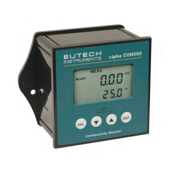
- Page 1 Instruction Manual lpha-CON560 Conductivity Controller mS/μS/ºC/ºF meter Technology Made Easy ... 68X216878 Rev 3 Aug 07 GlobalTestSupply www. .com Find Quality Products Online at: sales@GlobalTestSupply.com...
- Page 2 The information presented in this manual is subject to change without notice as improvements are made, and does not represent a commitment on part of Eutech Instruments. Eutech Instruments cannot accept any responsibility for damage or malfunction of the unit due to improper use of the instrument. Copyright 2006 All rights reserved.
-
Page 3: Table Of Contents
Table of Contents 1. Introduction ......................1 Before You Begin ........................1 Intended Use .......................... 1 Safety Instructions........................2 Taking Out of Service / Correct Disposal of the Unit ............. 2 2. Getting Started ......................3 Description of Instrument ....................... 3 Measurement and Control System..................4 Connecting Peripherals...................... - Page 4 10.3 Appendix 3 General Instructions Concerning Controller Setting ........38 10.4 Appendix 4 - Abbreviations Used in LCD................39 GlobalTestSupply www. .com Find Quality Products Online at: sales@GlobalTestSupply.com...
-
Page 5: Introduction
Instruction Manual lpha-CON 560 1. Introduction 1.1 Before You Begin We thank you for purchasing the lpha CON 560 controller. The construction of the CON 560 controller employs leading edge technology and complies with safety regulations currently in force. Notwithstanding this, improper use could lead to hazards for the user or a third-party, and/or adverse effects on the plant or other equipment. -
Page 6: Safety Instructions
Instruction Manual lpha-CON 560 1.3 Safety Instructions - The lpha CON 560 controller should be installed and operated only by personnel familiar with the instrument and who are qualified for such work. - A defective CON controller must neither be installed nor put into service. -
Page 7: Getting Started
Instruction Manual lpha-CON 560 2. Getting Started 2.1 Description of Instrument The Eutech Instruments’ lpha CON 560 controller is used for measuring conductivity and temperature values. The controller can be used for applications such water treatment controlling, galvanic- decontamination, chemical processing, food processing, clean or wastewater control and neutralization processes. -
Page 8: Measurement And Control System
Instruction Manual lpha-CON 560 2.2 Measurement and Control System A typical measurement system consists of: A conductivity process controller A conductivity sensor with integrated or separate Pt100/Pt1000 temperature sensor An appropriate measurement cable An immersion, flow or process assembly A final control element such as pump or valve Alpha CON 560 Controller Pump or Valve lpha pH560... -
Page 9: Connecting Peripherals
Instruction Manual lpha-CON 560 2.3 Connecting Peripherals 2.3.1 Connection Terminals Remove Back Cover: Remove the screws from the four corners at the back of the conductivity controller. Remove the back cover. The connectors are exposed on the back PCBA as shown in the Figure 1 below. Connectors: J8 –... -
Page 10: Switching Between Pt100 & Pt1000 Temperature Sensors
Instruction Manual lpha-CON 560 2.3.2 Switching Between Pt100 & Pt1000 Temperature Sensors The controller supports both Pt100 & Pt1000 (2-wire or 3-wire) temperature sensors. The default factory setting is Pt100. If you need to use Pt1000 temperature sensor, you have to change the jumper setting (J7) as described below. -
Page 11: Connecting Conductivity Probe
Instruction Manual lpha-CON 560 2.3.3 Connecting Conductivity Probe Any industrial conductivity probe (2-cell or 4-cell) can be connected to the conductivity controller. 2-Cell Conductivity Probe: 1. Short Pin 1 & 2 of J10 connector using a jumper wire. 2. Connect CON low input wire (white) to Pin 2 of J10 connector. 3. -
Page 12: Installation
Instruction Manual lpha-CON 560 2.4 Installation 2.4.1 Mechanical Dimensions lpha CON560 Conductivity Monitor 2.4.2 Wall Mount Pierce through holes at both sides Cover the catch slots at both sides with overlays GlobalTestSupply www. .com Find Quality Products Online at: sales@GlobalTestSupply.com... -
Page 13: Panel Mount
Instruction Manual lpha-CON 560 2.4.3 Panel Mount Prepare panel cut-out of 92.0 mm X 92.0 mm Remove back cover of conductivity controller and slide it through panel cut-out Gasket Panel Panel Insert threaded rods through catch until conductivity controller is held against panel Attach catch to both sides of conductivity controller... -
Page 14: Display & Keypad
Instruction Manual lpha-CON 560 2.5 Display & Keypad 2.5.1 Display Overview The Liquid Crystal Display (LCD) of lpha CON 560 conductivity controller has two alpha-numerical displays (Upper and a Lower). Upper display: Measured conductivity value is displayed when the controller is in normal operation (measurement) mode. Lower display: Measured temperature value is displayed when the controller is in normal operation (measurement) mode. -
Page 15: Key Functions
Instruction Manual lpha-CON 560 Units of Measurement Indicators Conductivity in Milli Siemens μS Conductivity in Micro Siemens Line Resistance in Ohms (Refer Section Temperature Coefficient (Refer Section 5.2 Temperature in Celsius ºC (Refer Section ºF Temperature in Fahrenheit (Refer Section 2.5.2 Key Functions lpha CON560 Conductivity Monitor... -
Page 16: Operation
Instruction Manual lpha-CON 560 3. Operation 3.1 Measurement mode When the conductivity controller is powered on, the display shows all the LCD segments briefly, and then automatically enters into the measurement mode. MEAS μS READY °C 2 5 . 0 The mode indicator ‘MEAS’... -
Page 17: Menu Overview
Instruction Manual lpha-CON 560 3.2 Menu Overview MEAS μS READY °C SETUP HOLD SETUP HOLD SETUP HOLD SETUP HOLD SETUP HOLD SETUP HOLD SETUP HOLD SETUP HOLD GlobalTestSupply www. .com Find Quality Products Online at: sales@GlobalTestSupply.com... -
Page 18: Calibration Mode
Instruction Manual lpha-CON 560 4. Calibration Mode 4.1 About Calibration Calibration should be carried out each time a new electrode is attached to the controller or when you suspect that the controller/electrode is out of calibration. The controller allows you to perform temperature calibration and conductivity calibration. -
Page 19: Calibration
Instruction Manual lpha-CON 560 4.2 Calibration The controller requires one-point calibration. Conductivity calibration is always carried out in the specific measuring range selected for the controller. Make sure, the controller is set to desired measuring range before you enter calibration mode (Refer Section 5.6 for selecting measuring ranges). Select a suitable standard conductivity solution so that its conductivity value is within 10% to 100% of the full scale of the selected measuring range of the controller. - Page 20 Instruction Manual lpha-CON 560 NOTES: The acceptable calibration window is ±40% of the displayed (default) value. For example, if the display is 1000 μS, the values to which it can be adjusted is 600 to 1400 μS. If the conductivity reading of the solution is not within 10% to 100% of the full scale of the selected measuring range, calibration error occurs;...
-
Page 21: Setup Mode
Instruction Manual lpha-CON 560 5. Setup Mode 5.1 Enter Setup mode The setup mode allows you to customize the settings of the conductivity controller to suite your requirements. While in measurement mode, press the ENT key to access setup mode. LCD shows ‘SETUP’ mode indicator and the first page of setup (rAng – Range settings). -
Page 22: Temperature Coefficient Settings
Instruction Manual lpha-CON 560 5.2 Temperature Coefficient Settings Setting the temperature coefficient to match your process/calibration liquids allows controller to achieve conductivity readings with higher accuracy. SETUP SETUP SETUP SETUP HOLD HOLD HOLD HOLD SETUP HOLD From measurement mode press ENT key to enter setup mode as described in section 5.1. -
Page 23: Temperature Settings
Instruction Manual lpha-CON 560 5.3 Temperature Settings Automatic Temperature Compensation (ATC): The conductivity value of a sample is affected by temperature. Use ATC feature of the controller to compensate for conductivity changes when the temperature of the sample or process liquid fluctuates. Connect a separate temperature probe (Pt100/pt1000) to the controller if an integrated conductivity/Temperature probe is not available. - Page 24 Instruction Manual lpha-CON 560 If ATC enabled (ATC On): Selecting temperature offset: The upper display shows the last configured temperature offset value (if any), otherwise the default is zero. The lower display shows currently measured temperature reading (including last configured offset value). LCD shows ‘ATC’ annunciator in lower-right corner.
-
Page 25: Relay 1/Relay 2 Settings
Instruction Manual lpha-CON 560 5.4 Relay 1/Relay 2 Settings NOTE: If controller type is set to ‘OFF’ (Refer section 5.5 for controller settings), the ‘Relay 1/Relay 2 Setting’ is not available. The SP1 settings determine the operating parameters for Relay 1; while SP2 settings define the operating parameters for Relay 2. - Page 26 Instruction Manual lpha-CON 560 This parameter lets you choose the relay function. Select ‘LO’ to NOTE: activate the relay when the conductivity reading undershoots the set point (SP1) or select ‘HI’ to activate the relay when the conductivity reading overshoots the set point (SP1). SP1 and SP2 can be selected as ‘LO/LO’, ‘LO/HI’, ‘HI/LO’, or ‘HI/HI’.
-
Page 27: Controller Settings
Instruction Manual lpha-CON 560 5.5 Controller Settings The controller settings allow you to set the relay type and relay status of the controller. SETUP SETUP HOLD HOLD SETUP SETUP HOLD HOLD SETUP HOLD From measurement mode press ENT key to enter setup mode as described in section 5.1. - Page 28 Instruction Manual lpha-CON 560 If Controller type was set to Off (OFF) The controller reverts to Cntr screen. If Controller type was set to On (L.Ct) Select the relay status under Non-Alarm condition: The lower display shows ‘rEL’. The upper display shows the last configured relay status.
-
Page 29: Measuring Range Settings
Instruction Manual lpha-CON 560 5.6 Measuring Range Settings The conductivity controller has 6 different measuring ranges. You need to select a range which is the most suitable for conductivity reading of your applications/samples. The factory default is 2000 μS (0 to 2000 μS/cm). The measuring range you select here will affect the way the controller behaves in the measurement mode and calibration mode. -
Page 30: Configuration Settings
Instruction Manual lpha-CON 560 5.7 Configuration Settings Configuration settings let you to enable/disable backlight of the LCD, select between 2-cell & 4-cell and reset the controller to factory defaults. SETUP SETUP SETUP SETUP HOLD HOLD HOLD HOLD This screen appears only when 2-cell is selected and measuring range is set to 0.0 to 200.0 mS/cm... - Page 31 Instruction Manual lpha-CON 560 Press key to select the cell type of your conductivity probe. Press ENT key to confirm your selection. NOTE: If you use a 2-cell conductivity sensor, make sure that the pin 1 and 2 are shorted and pin 3 and 4 are shorted on the J10 connector. (Refer section 2.3.3 for more details) Setting line resistance: The lower display shows ‘L.Ad’...
-
Page 32: Viewing Electrode Properties
Instruction Manual lpha-CON 560 5.8 Viewing Electrode Properties Each time you calibrate the conductivity sensor, the controller re-calculates the calibration factor of the sensor and shown in the LCD at the end of calibration. The setup mode allows you to view the last saved calibration factor and cell constant at any time. -
Page 33: Technical Specifications
Instruction Manual lpha-CON 560 6. Technical Specifications General Specification Conductivity Measuring Range: Resolution: 0.000 - 2.000 μS/cm 0.001 μS/cm 0.00 - 20.00 μS/cm 0.01 μS/cm 0.0 - 200.0 μS/cm 0.1 μS/cm 0- 2000 μS/cm 1 μS/cm 0.00 - 20.00 mS/cm 0.01 mS/cm 0.0 - 200.0 mS/cm 0.1 mS/cm... - Page 34 Instruction Manual lpha-CON 560 Other Power Input Universal +9 V DC Adaptor and 24V DC Supply Dimensions (W x H x D) 96mm x 96mm x 66 mm Weight (Estimated) 210g Ambient Temp. operating range 0 to 40 Maximum Relative Humidity 80% up to 31 C decreasing linearly to 50% at 40 Calibration Default Settings (CAL dEF)
-
Page 35: List Of Accessories
Instruction Manual lpha-CON 560 7. List of Accessories Controller Replacement and Accessories Item Description Order Code Alpha CON 560 Controller EC-PHCP0560 Conductivity cell, Epoxy body, Graphite sensor, w/3-wire Pt100, k = 0.1 EC-CONSEN89X Conductivity cell, Epoxy body, Graphite sensor, w/3-wire Pt100, k = 1.0 EC-CONSEN88X Conductivity 2 Cell type probe, 0.1 - 200 S;... -
Page 36: Troubleshooting
Instruction Manual lpha-CON 560 8. Troubleshooting Cause Problem Solution Power on, but no display a) Loose connections a) Ensure cables make good contact b) Incorrect output voltage of the power adaptor b) Use an power adaptor with specified output voltage c) Cables not in correct polarity (+ and –... -
Page 37: General Information
Dept. has to be informed in advance. Items must be carefully packed to prevent damage during shipment, and insured against possible damage or loss. Eutech Instruments will not be responsible for any damage resulting from careless or insufficient packing. Warning: Shipping damage as a result of inadequate packaging is the user's/distributor’s responsibility. -
Page 38: Appendices
Instruction Manual lpha-CON 560 10. Appendices 10.1 Appendix 2 Conductivity of various aqueous solutions At Temperature 25 C /77 Solution Conductivity Resistivity Ultra-pure Water 0.055 μS/cm 18.18 M -cm Power Plant Boiler Water 0.05 - 1 μS/cm 1 - 18 M -cm Distilled Water 0.5 μS/cm 2 M -cm... -
Page 39: Appendix 2 Graphical Representation Of The Function Of Hysteresis
Instruction Manual lpha-CON 560 10.2 Appendix 2 Graphical Representation of the Function of Hysteresis μS SP1 = 100 & Set to LO μS SP2 = 1900 & Set to HI RELAY ON μS RELAY OFF 1880 1900 Forward Direction Reverse Direction The relay of the conductivity controller activates when the set-point is reached (forward direction). - Page 40 Instruction Manual lpha-CON 560 10.3 Appendix 3 General Instructions Concerning Controller Setting Control characteristic of controller used as limit value switch MIN function MAX function 100% SP 2 Xp = 0 GlobalTestSupply www. .com Find Quality Products Online at: sales@GlobalTestSupply.com...
- Page 41 Instruction Manual lpha-CON 560 10.4 Appendix 4 - Abbreviations Used in LCD Abbreviation Description Automatic Temperature Compensation Calibration mode C.ºC Calibration temperature CdAt Electrode properties Cell CnFg Configuration Cntr Controller C.tC Temperature coefficient for calibration liquid Default values dEEn De-energized Energized Factory (defaults) High limit...