Table of Contents
Advertisement
GA-VM900M
Intel
Core
2 Duo / Intel
®
TM
Intel
Pentium
®
®
User's Manual
Rev. 2001
12ME-VM900M-2001R
* The WEEE marking on the product indicates this product must not be disposed of with user's other household waste
and must be handed over to a designated collection point for the recycling of waste electrical and electronic equipment!!
* The WEEE marking applies only in European Union's member states.
Pentium
®
4 / Celeron
D LGA775 Processor Motherboard
®
D /
®
Advertisement
Table of Contents
Troubleshooting

Related Manuals for Gigabyte GA-VM900M


Summary of Contents for Gigabyte GA-VM900M
- Page 1 GA-VM900M Intel Core 2 Duo / Intel ® Intel Pentium 4 / Celeron ® ® User's Manual Rev. 2001 12ME-VM900M-2001R * The WEEE marking on the product indicates this product must not be disposed of with user's other household waste and must be handed over to a designated collection point for the recycling of waste electrical and electronic equipment!! * The WEEE marking applies only in European Union's member states.
- Page 3 Gigabyte's prior written permission. Specifications and features are subject to change without prior notice. Product Manual Classification In order to assist in the use of this product, Gigabyte has categorized the user manual in the following: For detailed product information and specifications, please carefully read the "Product User Manual".
-
Page 4: Table Of Contents
Table of Contents Box Contents ... 6 Optional Items ... 6 GA-VM900M Motherboard Layout ... 7 Block Diagram ... 8 Chapter 1 Hardware Installation ... 9 Considerations Prior to Installation ... 9 Feature Summary ... 10 Installation of the CPU and CPU Cooler ... 12 1-3-1 Installation of the CPU ... - Page 5 Chapter 3 Drivers Installation ... 45 Installing Chipset Drivers ... 45 Software Applications ... 46 Driver CD Information ... 46 Hardware Information ... 47 Contact Us ... 47 Chapter 4 Appendix ... 49 Unique Software Utilities ... 49 4-1-1 EasyTune 5 Introduction ... 49 4-1-2 Xpress Recovery2 Introduction ...
-
Page 6: Box Contents
Box Contents GA-VM900M motherboard Motherboard driver disk User's Manual Intel LGA775 CPU Installation Guide ® One IDE cable and one floppy disk drive cable One SATA 3Gb/s cable I/O Shield The box contents above are for reference only and the actual items shall depend on product package you obtain. -
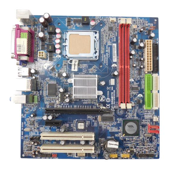
Page 7: Ga-Vm900M Motherboard Layout
GA-VM900M Motherboard Layout KB_MS ATX_12V AUDIO F_AUDIO PCIE_16 RTL8201 PCIE_1 PCI1 CD_IN PCI2 CODEC SPDIF_IO HDA_SUR CPU_FAN LGA775 P4M900 BIOS CLR_CMOS BATTERY COMB F_USB1 - 7 - IDE1 IDE2 SYS _FAN SATAII1 VT8237S SATAII0 F_PANEL F_USB2... -
Page 8: Block Diagram
Block Diagram PCIe CLK (100 MHz) PCI Express x16 PCI Express Bus PCIe CLK (100 MHz) PCI Express x1 PCI Bus RJ45 2 PCI PCI CLK (33 MHz) (Note) Use of a 1066/800 MHz FSB CPU is required if you wish to install DDR2 667 MHz memory. LGA775 Processor D-Sub... -
Page 9: Chapter 1 Hardware Installation
2. Damage as a result of violating the conditions recommended in the user manual. 3. Damage due to improper installation. 4. Damage due to use of uncertified components. 5. Damage due to use exceeding the permitted parameters. 6. Product determined to be an unofficial Gigabyte product. - 9 - Hardware Installation... -
Page 10: Feature Summary
1 S/PDIF In/Out connector 2 USB 2.0/1.1 connectors for additional 4 USB 2.0/1.1 ports by cables 1 COMB connector 1 chassis intrusion connector 1 power LED connector GA-VM900M Motherboard Core 2 Duo / Pentium ® (Note 1) - 10 - D / Pentium ®... - Page 11 Rear Panel I/O 1 PS/2 keyboard port 1 PS/2 mouse port 1 parallel port 1 serial port 1 D-Sub port 4 USB 2.0/1.1 ports 1 RJ-45 port 3 audio jacks (Line In / Line Out / MIC In) I/O Control Winbond W83627 chip Hardware Monitor System voltage detection...
-
Page 12: Installation Of The Cpu And Cpu Cooler
Avoid twisting or bending motions that might cause damage to the CPU during installation.) GA-VM900M Motherboard Fig. 2 Remove the plastic covering on the CPU socket. -
Page 13: Installation Of The Cpu Cooler
1-3-2 Installation of the CPU Cooler Fig.1 Please apply an even layer of CPU cooler paste on the surface of the installed CPU. Fig. 3 Place the CPU cooler atop the CPU and make sure the push pins aim to the pin hole on the motherboard.Pressing down the push pins diagonally. -
Page 14: Installation Of Memory
The motherboard supports DDR2 memory modules, whereby BIOS will automatically detect memory capacity and specifications. Memory modules are designed so that they can be inserted only in one direction. The memory capacity used can differ with each slot. GA-VM900M Motherboard DDR2 DIMM Fig.1 The DIMM socket has a notch, so the DIMM memory module can only fit in one direction. -
Page 15: Installation Of Expansion Cards
Installation of Expansion Cards Follow the steps below to correctly install your expansion card in the expansion slot. 1. Locate an expansion slot that supports your card. Remove the metal slot cover from the chassis back panel. 2. Align the card with the slot, and press down on the card until it is fully seated in the slot. 3. -
Page 16: I/O Back Panel Introduction
To configure 7.1-channel audio, you need to install a 5.1/7.1 surround cable (optional) and enable the multi-channel audio feature through the audio driver. Refer to the instructions on setting up a 2/4/5.1/7.1-channel audio configuration in Chapter 4, "Configuring 2/4/5.1/7.1- Channel Audio Introduction." GA-VM900M Motherboard Connection LED: Description Data transmission or receiving is occurring... -
Page 17: Connectors Introduction
Connectors Introduction ATX_12V ATX (Power Connector) CPU_FAN SYS_FAN IDE1 / IDE2 SATAII0 / SATAII1 F_PANEL PWR_LED 16 17 F_AUDIO CD_IN SPDIF_IO HDA_SUR F_USB1 / F_USB2 COMB CLR_CMOS BATTERY - 17 - Hardware Installation... - Page 18 If you use a 24-pin ATX power supply, please remove the small cover on the power connector on the motherboard before plugging in the power cord ; Otherwise, please do not remove it. GA-VM900M Motherboard ATX_12V : Pin No.
- Page 19 3/4) CPU_FAN / SYS_FAN (Cooler Fan Power Connector) The cooler fan power connector supplies a +12V power voltage via a 3-pin/4-pin(CPU_FAN) power connector and possesses a foolproof connection design. Most coolers are designed with color-coded power connector wires. A red power connector wire indicates a positive connection and requires a +12V power voltage.
- Page 20 Each SATA connector supports a single SATA device. The VT8237S controller supports RAID 0 and RAID 1. Refer to Chapter 4, "Configuring SATA Hard Drive(s)," for instructions on configuring a RAID array. A RAID 0 or RAID 1 configuration requires two hard drives. GA-VM900M Motherboard IDE1 IDE2 Pin No.
-
Page 21: F_Panel (Front Panel Connector)
F_PANEL (Front Panel Connector) Please connect the power LED, PC speaker, reset switch and power switch etc. of your chassis front panel to the F_PANEL connector according to the pin assignments below. MSG (Message LED/Power/Sleep LED) PW (Power Switch) SPEAK (Speaker Connector) HD (IDE Hard Disk Active LED) RES (Reset Switch) Speaker Connector... -
Page 22: Front Audio Connector
By default, the audio driver is configured to support HD Audio. To connect an AC'97 front panel audio module to this connector, please refer to the instructions on page 71 about the software settings. GA-VM900M Motherboard Pin No. Definition MPD+... - Page 23 11) CD_IN (CD In Connector, black) Connect CD-ROM or DVD-ROM audio out to the connector. 12) SPDIF_IO (S/PDIF In/Out connector, red) The S/PDIF output is capable of providing digital audio to external speakers or compressed AC3 data to an external Dolby Digital Decoder. Use this feature only when your stereo system has digital input function.
- Page 24 14) F_USB1 / F_USB2 (Front USB Connectors) The connectors conform to USB 2.0/1.1 specification. Each USB header can provide two USB ports via an optional USB bracket. For purchasing the optional USB bracket, please contact the local dealer. GA-VM900M Motherboard Pin No. Definition LEF_P...
- Page 25 15) COMB (COMB Connector) The COMB connector can provide one serial port via an optional COM port cable. For purchasing the optional COM port cable, please contact the local dealer. 16) CI (Chassis Intrusion Header) This motherboard provides a chassis detection feature that detects if the chassis cover has been removed.
- Page 26 18) BATTERY GA-VM900M Motherboard Open: Normal Short: Clear CMOS Danger of explosion if battery is incorrectly replaced.
-
Page 27: Chapter 2 Bios Setup
CMOS SETUP screen. You can enter the BIOS setup screen by pressing "Ctrl + F1". If you wish to upgrade to a new BIOS, either GIGABYTE's Q-Flash or @BIOS utility can be used. Q-Flash allows the user to quickly and easily update or backup BIOS without entering the operating system. -
Page 28: The Main Menu (For Example: Bios Ver. : Fam)
This action makes the system reset to the default settings for stability. 3. The BIOS Setup menus described in this chapter are for reference only and may differ from the exact settings for your motherboard. GA-VM900M Motherboard <F12> : Boot Menu Boot Menu... - Page 29 Standard CMOS Features This setup page includes all the items in standard compatible BIOS. Advanced BIOS Features This setup page includes all the items of Award special enhanced features. Integrated Peripherals This setup page includes all onboard peripherals. Power Management Setup This setup page includes all the items of Green function features.
-
Page 30: Standard Cmos Features
Allows BIOS to automatically detect IDE/SATA devices during POST(default) • None Select this if no IDE/SATA devices are used and the system will skip the automatic detection step and allow for faster system start up. GA-VM900M Motherboard Standard CMOS Features Tue, May 29 2007 14:31:24... - Page 31 Access Mode Use this to set the access mode for the hard drive. The two options are: Large/Auto(default:Auto) Capacity Capacity of currently installed hard drive. Hard drive information should be labeled on the outside drive casing. Enter the appropriate option based on this information.
-
Page 32: Advanced Bios Features
Floppy Select your boot device priority by Floppy. LS120 Select your boot device priority by LS120. (Note) This item will show up when you install a processor which supports this function. GA-VM900M Motherboard Advanced BIOS Features [PEG] [Disabled] [64M] [Press Enter]... - Page 33 Hard Disk Select your boot device priority by Hard Disk. CDROM Select your boot device priority by CDROM. Select your boot device priority by ZIP. USB-FDD Select your boot device priority by USB-FDD. USB-ZIP Select your boot device priority by USB-ZIP. USB-CDROM Select your boot device priority by USB-CDROM.
-
Page 34: Integrated Peripherals
Auto Auto detect the onboard Azalia audio function. (Default value) Disabled Disable this function. LAN Controller Enabled Enable the onboard LAN function. (Default value) Disabled Disable this function. GA-VM900M Motherboard Integrated Peripherals [Enabled] [IDE] [Enabled] [Enabled] [Enabled] [Enabled] [Auto] [Enabled]... - Page 35 USB 1.1 Controller Enabled Enable the USB 1.1 controller. (Default value) Disabled Disable this function. USB 2.0 Controller Enabled Enable the USB 2.0 controller. (Default value) Disabled Disable this function. USB Keyboard Support Enabled Enable the USB keyboard support. Disabled Disable this function.
- Page 36 This item is configurable only if the Parallel Port Mode option is set to EPP or ECP+EPP mode. EPP1.7 Set LPT port use EPP 1.7. (Default value) EPP1.9 Set LPT port use EPP 1.9. GA-VM900M Motherboard - 36 -...
-
Page 37: Power Management Setup
Power Management Setup CMOS Setup Utility-Copyright (C) 1984-2007 Award Software USB Resume from S3 ACPI Suspend Type Soft-Off by PWRBTN AC BACK Function PS2KB Power On Select PS2 Mouse Power On PME Event Wake Up Modem Ring Resume Resume by Alarm x Date (of Month) x Resume Time (hh:mm:ss) : Move... - Page 38 Disable this function. (Default value) Enabled Enable alarm function to POWER ON system. If Resume by Alarm is Enabled. Date (of Month) : Everyday, 1~31 Resume Time (hh: mm: ss) : (0~23) : (0~59) : (0~59) GA-VM900M Motherboard - 38 -...
-
Page 39: Pnp/Pci Configurations
PnP/PCI Configurations CMOS Setup Utility-Copyright (C) 1984-2007 Award Software PCI 1 IRQ Assignment PCI 2 IRQ Assignment : Move Enter: Select F5: Previous Values PCI 1 IRQ Assignment Auto 3,4,5,7,9,10,11,12,14,15 PCI 2 IRQ Assignment Auto 3,4,5,7,9,10,11,12,14,15 PnP/PCI Configurations [Auto] [Auto] +/-/PU/PD: Value F10: Save ESC: Exit... -
Page 40: Pc Health Status
Monitor system/CPU temperature at 90 Disabled Disable this function. (Default value) SYS/CPU FAN Fail Warning Disabled Disable the fan fail warning function. (Default value) Enabled Enable the fan fail warning function. GA-VM900M Motherboard PC Health Status [Disabled] C/114 C/116 2880 RPM [Disabled] [Disabled]... - Page 41 CPU Smart FAN Control Disabled Disable this function. Enabled When this function is enabled, CPU fan will run at different speed depending on CPU temperature. Users can adjust the fan speed with EasyTune based on their requirements. (Default value) - 41 - BIOS Setup...
-
Page 42: Load Fail-Safe Defaults
PC Health Status ESC: Quit F8: Q-Flash Selecting this field loads the factory defaults for BIOS and Chipset Features which the system automati- cally detects. GA-VM900M Motherboard Load Fail-Safe Defaults Load Optimized Defaults Set Supervisor Password Set User Password Load Fail-Safe Defaults (Y/N)? N Save &... -
Page 43: Set Supervisor/User Password
Set Supervisor/User Password CMOS Setup Utility-Copyright (C) 1984-2007 Award Software Standard CMOS Features Advanced BIOS Features Integrated Peripherals Power Management Setup Enter Password: PnP/PCI Configurations PC Health Status ESC: Quit F8: Q-Flash When you select this function, the following message will appear at the center of the screen to assist you in creating a password. -
Page 44: Save & Exit Setup
PC Health Status ESC: Quit F8: Q-Flash Type "Y" will quit the Setup Utility without saving to RTC CMOS. Type "N" will return to Setup Utility. GA-VM900M Motherboard Load Fail-Safe Defaults Load Optimized Defaults Set Supervisor Password Set User Password Save to CMOS and EXIT (Y/N)? Y Save &... -
Page 45: Chapter 3 Drivers Installation
Chapter 3 Drivers Installation • Before installing the drivers, first install the operating system. (The following instructions use Windows XP as the example operating system.) • After installing the operating system, insert the motherboard driver disk into your optional drive. The driver Autorun screen is automatically displayed which looks like that shown in the screen shot below. -
Page 46: Software Applications
Software Applications This page displays all the tools and applications that GIGABYTE develops and some free software. You may press the Install button following an item to install it. Driver CD Information This page provides information about the drivers, applications and tools in this driver disk. -
Page 47: Hardware Information
Hardware Information This page provides information about the hardware devices on this motherboard. Contact Us Check the contacts information of the GIGABYTE headquarter in Taiwan and the overseas branch offices on the last page of this manual. - 47 -... - Page 48 GA-VM900M Motherboard - 48 -...
-
Page 49: Chapter 4 Appendix
EASY MODE/ADVANCED MODE Display Field Function LEDs GIGABYTE Logo Help Exit or Minimize (Note) EasyTune 5 functions may vary depending on different motherboards. (Note) Description Enters the Overclocking setting page Enters the C.I.A. and M.I.B. setting page Enters the Smart-Fan setting page... -
Page 50: Xpress Recovery2 Introduction
2. System storage capacity and the reading/writing speed of the hard disk will affect the data backup speed. 3. It is recommended that Xpress Recovery2 be immediately installed once you complete installations of OS and all required drivers as well as software. GA-VM900M Motherboard Boot from CD/DVD: <F9> Xpress Recovery2 - 50 -... - Page 51 2. It is normal that data backup takes longer time than data restoration. 3. Xpress Recovery2 is compliant with the GPL regulations. 4. On a few motherboards based on Nvidia chipsets, BIOS update is required for Xpress Recovery2 to correctly identify RAID and SATA IDE mode. Please contact your motherboard manufacturer.
-
Page 52: Flash Bios Method Introduction
Before Use: Follow the steps below before using Q-Flash to update BIOS: 1. From GIGABYTE's website, download the latest compressed BIOS update file that matches your motherboard model 2. Extract the downloaded BIOS files and save the new BIOS file (e.g. VM900M.FA) to your floppy disk or hard disk. - Page 53 c . Select the BIOS file and press ENTER. Make sure again the BIOS file matches your motherboard model. Step 2: The process of system reading the BIOS file from the floppy disk is displayed on the screen. When the message "Are you sure to update BIOS?" appears, press ENTER. The BIOS update will begin and the current process will be displayed.
- Page 54 Fig 3. The @BIOS Utility Click "Update New BIOS" Click " " 1. Methods and steps: I. Update BIOS through Internet Click "Find BIOS From Gigabyte" icon Click "Update New BIOS" icon Select @BIOS sever Select the exact model name on your motherboard System will automatically download and update the BIOS.
- Page 55 Otherwise, your system won't boot. III. In method I, if the BIOS file you need cannot be found in @BIOS Gigabyte's web site for downloading and updating it according to method II. IV. Please note that any interruption during updating will cause system unbooted.
-
Page 56: Configuring Sata Hard Drive(S)
Make sure that the SATA Controller under the Integrated Peripherals menu is enabled. To create RAID, set SATA Controller Mode (Figure 1) to RAID (IDE by default). Set SATA Controller Mode to IDE if you do not want to create RAID. (Note) Required for setting up RAID array. GA-VM900M Motherboard (Note) (Note) (Note) - Page 57 CMOS Setup Utility-Copyright (C) 1984-2007 Award Software SATA Controller SATA Controller Mode IDE DMA transfer access OnChip IDE Channel0 OnChip IDE Channel1 IDE Prefetch Mode Azalia HDA Controller LAN Controller USB 1.1 Controller USB 2.0 Controller USB Keyboard Support USB Mouse Support OnBoard LAN Boot ROM Legacy USB storage detect Onboard Serial Port 1...
- Page 58 Select/Clear Boot Array Serial Number View Dev. Posi. Drive Name Channel0 Master ST3120026AS Channel1 Master ST3120026AS GA-VM900M Motherboard ST3120026AS ST3120026AS Figure 3 VIA VT8237S V-RAID Utility V1.20 Create a RAID array with the hard disks attached to VIA RAID controller...
- Page 59 A. Create Array: In Main Menu, select Create Array and press ENTER, a screen similar to Figure 5 below will appear. Auto Setup For Data Security Array Mode RAID 1 (Mirroring) Select Disk Drives Start Create Process Dev. Posi. Drive Name Channel0 Master ST3120026AS Channel1 Master...
- Page 60 Continue? (Y/N)" will appear. Press Y to confirm or N to abort. Important All existing contents in the hard drive will be destroyed after the array creation. GA-VM900M Motherboard VIA VT8237S V-RAID Utility V1.20 Create a RAID array with...
- Page 61 B. View Array Status: Press F1 to show the array status on the lower screen. If there are no disk arrays then nothing will be displayed on the screen (Figure 9). Create Array Delete Array Select/Clear Boot Array Serial Number View View Array/Disks Status..
- Page 62 Deleting a disk array will destroy all the data on the disk array except for RAID 1 array(s). When a RAID 1 array is deleted, the data on the two hard drives will be reserved and the two hard drives will become two normal drives. GA-VM900M Motherboard VIA VT8237S V-RAID Utility V1.20 View the serial number of hard disks, it is userful for identify same model disks.
- Page 63 0 to exit when finished. (Note) For users without a startup disk: Use an alternative system and insert the GIGABYTE motherboard driver CD-ROM. From the CD-ROM drive folder, double click the MENU.exe file in the BootDrv folder (Figure 15). A command prompt window will open similar to that in Figure 14.
- Page 64 * If you do not have any device support disks from a mass storage device manufacturer, or do not want to specify additional mass storage devices for use with Windows, press ENTER. S=Specify Additional Device ENTER=Continue F3=Exit GA-VM900M Motherboard Figure 16 Figure 17 - 64 -...
- Page 65 Step 3: If Setup correctly recognizes the driver in the floppy disk, a controller menu similar to Figure 18 below will appear. If you want to install Windows XP, use the ARROW keys to select VIA V-RAID Controller Series (Windows XP/SRV2003) (Note) the floppy disk.
- Page 66 Windows (R) XP to run on your computer. To set up Windows XP now, press ENTER. To repair a Windows XP installation using Recovery Console, press R. To quit Setup without installing Windows XP, press F3. Enter= Continue GA-VM900M Motherboard R=Repair F3=Exit Figure 20 - 66 -...
-
Page 67: 4- / 5.1- / 7.1- Channel Audio Introduction
4-1-5 2- / 4- / 5.1- / 7.1- Channel Audio Introduction This motherboard comes with three audio jacks. To set up multi-channel surround sound, install an additional 5.1/7.1 surround cable (optional) and enable the feature through the audio driver. Installing the 5.1/7.1 Surround Cable (Optional) The 5.1/7.1 Surround Cable provides center/ subwoofer speaker out, rear speaker out, and side speaker out audio jacks. - Page 68 Double-click the icon to open the Audio Control Panel. STEP 2: In the Audio Control Panel, click the Speaker tab. In the left list, click the 2 Channel button. The 2-channel audio setup is completed. GA-VM900M Motherboard - 68 -...
- Page 69 Setting Up 4-Channel Audio STEP 1 : After installation of the audio driver, you should find a VIA HD Audio Deck icon in your system tray. Double-click the icon to open the Audio Control Panel. STEP 2: In the Audio Control Panel, click the Speaker tab. In the left list, click the 4 Channel button.
- Page 70 Double-click the icon to open the Audio Control Panel. STEP 2: In the Audio Control Panel, click the Speaker tab. In the left list, click the 8 Channel button. The 7.1-channel audio setup is completed. GA-VM900M Motherboard - 70 -...
- Page 71 Auto-detecting: In the Audio Control Panel, click the Jack tab. Click the Auto Show Dialog checkbox will enable the Retasking function. A Retasking dialog will show up when you plug the audio device into the jacks. Click the right output device checkbox that you connect in, then press OK.
-
Page 72: Troubleshooting
1 long, 2 short: Monitor or graphics card error 1 long, 3 short: Keyboard error 1 long, 9 short: BIOS ROM error Continuous long beeps: Graphics card not inserted properly Continuous short beeps: Power error GA-VM900M Motherboard - 72 -... -
Page 73: Troubleshooting Procedure
4-2-2 Troubleshooting Procedure If you encounter any troubles during system startup, follow the troubleshooting procedure below to solve the problem. START Turn off the power. Remove all peripherals, connecting cables, and power cord etc. Make sure the motherboard does not short-circuit with the chassis or other metal objects. - Page 74 If the procedure above is unable to solve your problem, contact the place of purchase or local dealer for help. Or go to the Support\Technical Service Zone page to submit your question. Our customer service staff will reply you as soon as possible. GA-VM900M Motherboard - 74 - The power supply, CPU or CPU socket might fail.
-
Page 75: Windows Vista Readyboost
Windows Vista ReadyBoost Windows ReadyBoost allows you to use flash memory on a Windows Vista certified USB flash drive to boost your computer's performance. You may enable ReadyBoost and allocate part of your USB flash drive's memory to speed up your computer. Follow the steps below to enable the ReadyBoost function: Step 1: Go to Computer. - Page 76 GA-VM900M Motherboard - 76 -...
- Page 77 - 77 - Appendix...
- Page 78 GIGA-BYTE TECHNOLOGY CO., LTD. Address: No.6, Bau Chiang Road, Hsin-Tien, Taipei 231, Taiwan TEL: +886-2-8912-4888 FAX: +886-2-8912-4003 Tech. and Non-Tech. Support (Sales/Marketing) : http://ggts.gigabyte.com.tw WEB address (English): http://www.gigabyte.com.tw WEB address (Chinese): http://www.gigabyte.tw U.S.A. G.B.T. INC. TEL: +1-626-854-9338 FAX: +1-626-854-9339 Tech. Support: http://rma.gigabyte-usa.com...
- Page 79 Representative Office Of GIGA-BYTE Technology Co., Ltd. in SERBIA & MONTENEGRO WEB address : http://www.gigabyte.co.yu You may go to the GIGABYTE website, select your language in the language list on the top right corner of the website. To submit a technical or non-technical (Sales/ Marketing) question, please link to : http://ggts.gigabyte.com.tw...
- Page 80 - 80 -...