
Related Manuals for Fluke FL1730-BAS


Summary of Contents for Fluke FL1730-BAS
- Page 1 1730 Energy Logger Users Manual September 2013 © 2013 Fluke Corporation. All rights reserved. Specifications are subject to change without notice. All product names are trademarks of their respective companies.
- Page 2 LIMITED WARRANTY AND LIMITATION OF LIABILITY Each Fluke product is warranted to be free from defects in material and workmanship under normal use and service. The warranty period is two years and begins on the date of shipment. Parts, product repairs, and services are warranted for 90 days. This warranty extends only to the original buyer or end-user customer of a Fluke authorized reseller, and does not apply to fuses, disposable batteries, or to any product which, in Fluke's opinion, has been misused, altered, neglected, contaminated, or damaged by accident or abnormal conditions of operation or handling.
-
Page 3: Table Of Contents
Table of Contents Title Page Introduction ........................1 How to Contact Fluke ....................2 Safety Information ......................2 Before You Start ......................5 Tilt Stand ........................6 Hanger Accessory ..................... 6 Storage .......................... 7 Power Supply ........................ 7 How to Charge Battery ....................8 Accessories ........................ - Page 4 1730 Users Manual Touch Screen ......................17 Brightness Button ....................17 Calibration ......................17 Basic Navigation ....................... 17 Function Selection Buttons .................... 18 Meter ......................... 18 Power ........................25 Logger ........................25 Memory/Settings Button .................... 29 Logging Sessions ....................29 Screen Capture ....................
- Page 5 List of Tables Table Title Page Symbols ..........................4 Accessories .......................... 9 Front Panel ........................... 12 Connector Panel ........................13 Power/Battery Status ......................16 Replacement Parts ....................... 38...
- Page 6 1730 Users Manual...
- Page 7 List of Figures Figure Title Page Country-Specific Mains Cords ....................5 Hanger Accessory ........................ 6 Power Supply and Battery ....................7 R-Coil Operation Principle ....................10 Test Leads with Color Coding ....................11 Front Panel ........................... 12 Connector Panel ........................13 Decal for Connector Panel ....................
- Page 8 1730 Users Manual...
-
Page 9: Introduction
Harmonic Distortion: Total Harmonic Distortion of location. Voltage and Current The Logger makes these measurements: Fluke Energy Analyze software is included with the • Product for a thorough energy analysis and professional Basic Measurements: Voltage (V), Current (A), report of the measurement results. -
Page 10: How To Contact Fluke
1730 Users Manual How to Contact Fluke Safety Information To contact Fluke, use one of these telephone numbers: A Warning identifies hazardous conditions and procedures that are dangerous to the user. A Caution • USA: 1-800-760-4523 identifies conditions and procedures that can cause •... - Page 11 Energy Logger Safety Information • • Use Product-approved measurement Do not touch voltages >30 V ac rms, category (CAT), voltage, and amperage 42 V ac peak, or 60 V dc. rated accessories (probes, test leads, and • Do not apply more than the rated voltage, adapters) for all measurements.
- Page 12 Conforms to relevant North American Safety recycler or hazardous materials handler per local Standards regulations. Contact your authorized Fluke Service Center for recycling information. Conforms to European Union directives This product complies with the WEEE Directive ...
-
Page 13: Before You Start
See Figure 1. • Documentation Info Pack (Quick Reference Card, Safety Information, Battery Pack Safety Information, iFlex Probe Safety Information, i40s-EL Current Clamp Safety Information • 4 GB USB Flash Drive (includes Users Manual and PC application software, Fluke Energy Analyze) -
Page 14: Tilt Stand
1730 Users Manual Tilt Stand The power supply includes a tilt stand. When used, the tilt stand positions the display at a good angle for use on a tabletop surface. To use, attach the power supply to the Logger and open the tilt stand. Hanger Accessory The optional hanger accessory shown in Figure 2 is used •... -
Page 15: Storage
Energy Logger Storage The power cord/measurement line cover slides to select Storage the input source. When not in use, keep the Logger in the protective storage bag/case. The bag/case has sufficient space for the Warning Logger and all the accessories. To prevent possible electrical shock, fire, or personal injury, do not use the power supply if If the Logger is stored for an extended period of time or is... -
Page 16: How To Charge Battery
1730 Users Manual Caution How to Charge Battery To prevent damage to the Product: The Logger also operates on an internal rechargeable Lithium-ion battery. After you unpack and inspect the • Do not leave batteries unused for extended Logger, fully charge the battery before first use. periods of time, either in the product or in Afterwards, charge the battery when the battery icon on storage. -
Page 17: Accessories
Set of three Thin-Flexi Current Probes 3000 A 61 cm (24 in) 4345625 i1730-flex 6000 Thin-Flexi Current Probe (single) i1730-flex6000/3PK 4357423 Set of three Thin-Flexi Current Probes 6000 A 90.5 cm (36 in) Fluke-1730 Test Lead, 0.10 m 4344653 Fluke-1730 Test Lead, 2 m 4344675... -
Page 18: Thin-Flexi Current Probe
1730 Users Manual The R-coil has many advantages over other types of Thin-Flexi Current Probe current transformers: The Thin-Flexi Current Probe works on the Rogowski coil (R-coil) principle that is a toroid of wire used to measure • It is not a closed loop. The second terminal is passed an alternating current through a cable encircled by the back through the center of the toroid core (commonly a toroid. -
Page 19: Test Leads
Energy Logger Accessories Test Leads Kensington Lock Test leads are four-core, flat, test leads that do not tangle A Kensington Security Slot (also called a K-Slot or and can be installed in tight spaces. On installations where Kensington lock) is part of a built-in anti-theft system. It is the access to Neutral is out of reach with the three-phase a small, metal-reinforced, oval hole found on the right side test lead, use the black test lead to extend the Neutral... -
Page 20: Navigation And User Interface
1730 Users Manual Navigation and User Interface Table 3. Front Panel See Figure 8 and Table 3 for a list of the front panel Item Control Description controls and their functions. See Figure 7 and Table 4 is a Power on/off and status list of the connectors and their functions. - Page 21 Energy Logger Navigation and User Interface Table 4. Connector Panel Item Description Current measurement inputs (3 phases) Voltage measurement inputs (3 phases) Power Cord/Measurement Line Slide-Cover Power Cord AC Input 100-240 V 50/60 Hz 15 VA Measurement line AC Input ...
-
Page 22: Applying The Connector Panel Decal
1730 Users Manual Applying the Connector Panel Decal USA (4275029) Canada (4280546) Self-adhesive decals are supplied with the Logger. The decals correspond to the wiring color codes used in the USA, Europe and UK, UK (old), Canada, and China. Apply the decal appropriate for your local wiring codes around the current and voltage inputs on the connector panel as Europe/UK (New STD 4280531) -
Page 23: Power On/Off
Energy Logger Navigation and User Interface For 3-phase delta systems connect the safety sockets Power ON/OFF of the power supply with the input sockets A/L1 and The Logger has several options for power: mains, B/L2. measurement line, and battery. The front panel LED shows the status. -
Page 24: Power From Battery
1730 Users Manual Power from Battery The Logger can operate on battery power without a connection to the power supply or dc power cord. Push . The Logger turns on and is ready to use in <20 seconds. The battery symbol in the status bar and the power LED indicate the battery status. -
Page 25: Touch Screen
Energy Logger Navigation and User Interface Touch Screen Calibration The touch screen enables you to interact directly with what The touch screen is pre-calibrated in the factory. If you is on the display. To change parameters, touch a target on notice that the targets do not align with your touch on the the display with a finger. -
Page 26: Function Selection Buttons
1730 Users Manual Function Selection Buttons Study Type Depending on the application, select either Load Study or The Logger has three buttons that toggle between the Energy Study. Meter, Power, and Logger function modes. The current mode shows in the upper left corner of the display: •... - Page 27 Energy Logger Function Selection Buttons Single Phase Single Phase IT Example: Branch circuit at an outlet. The logger has a galvanic isolation between the voltage inputs and ground based signals like USB and mains input. A/L1 Example: Used in Norway and in some hospitals. This would be the connection at a branch circuit.
- Page 28 1730 Users Manual Split Phase 3-Ф Wye Example: A North American residential installation at the Example: Also called “Star” or four-wire connection. service entrance. Typical commercial building power. A/L1 A/L1 B/L2 B/L2 C/L3 hcf045.eps hcf043.eps Energy Study Energy Study A/L1 A/L1 B/L2 C/L3...
- Page 29 Energy Logger Function Selection Buttons 3-Ф Wye IT 3-Ф Wye Balanced The logger has a galvanic isolation between the voltage Example: For symmetrical loads like motors the inputs and ground based signals like USB and mains connection can be simplified by measuring only one phase input.
- Page 30 1730 Users Manual 3-Ф Delta Open Leg 3-Ф Delta Example: A variant of power transformer winding type. Example: Often found in industrial settings where electric motors are used. A/L1 A/L1 B/L2 C/L3 B/L2 C/L3 hcf053.eps Energy Study hcf051.eps Energy Study A/L1 A/L1 B/L2...
- Page 31 Energy Logger Function Selection Buttons 2 Element Delta (Aron/Blondel) Nominal Voltage: Load Studies Only Example: Blondel or Aron connection, simplifies the Select a nominal voltage from the list. If a voltage is not connection by the use of only two current sensors. shown in the list, a custom voltage can be entered.
- Page 32 1730 Users Manual In the connection verification screen: Voltage Ratio (only in energy studies) Configure a ratio factor for the voltage inputs when a 1. Push (Correct Digitally) to access the connection potential transformer (PT) is in series with the voltage correction screen.
-
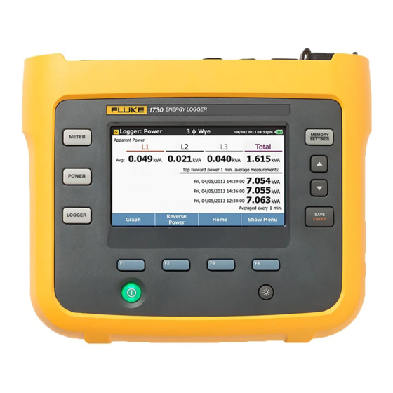
Page 33: Power
Energy Logger Function Selection Buttons Power Logger – In the Power mode you can get the values and a – In Logger mode, you can: live trend chart for each phase (A, B, C or L1, L2, L3) and •... - Page 34 1730 Users Manual measurement configuration. After you review these Duration parameters, push the Start Logging touch target to start Select the duration of the measurement from the list. The recording. logging session stops automatically when the time duration If you want to modify the parameters, push the Edit Setup has elapsed.
- Page 35 Energy Logger Function Selection Buttons Demand Interval Description Electrical suppliers use this interval to measure the Enter more details about the measurement, such as customer demand. Select an interval to get energy costs customer, location, and load-rating plate data with the and the maximum demand value (average power virtual keyboard.
- Page 36 1730 Users Manual In the "V, A, Hz, +", "Power" and "Energy" screens, use Push (Graph) to display the measured values in a (Show Menu) or the cursor keys to see a list of chart. The table on the right side of the screen shows the available parameters.
-
Page 37: Memory/Settings Button
Energy Logger Function Selection Buttons Push (Graph) to display the measured values in a Details chart. The table on the right side of the screen shows the The details screen provides an overview of the logging highest and lowest value of the graph measured with the setup. -
Page 38: Screen Capture
1730 Users Manual Note Instrument Settings It is not possible to review a completed logging The Logger has settings for language, date and time, session when another session is active. phase information, firmware version and update, and calibration. 2. Push (Delete) to remove the selected logging session. - Page 39 Energy Logger Function Selection Buttons Phase Color/Phase Labels Date/Time Zone The phase colors are configurable to match with the The logger stores the measurement data in universal time connector panel decal. Five schemes are available: coordinate (UTC) to ensure continuity in time and accounts for time changes due to daylight saving time (DST).
-
Page 40: Touch Screen Calibration
1730 Users Manual 4. Push to toggle between a 12 hour or 24 hour Touch Screen Calibration format. A preview of the configured date format shows The touch screen has been calibrated at the factory before on the display. shipment. -
Page 41: Firmware Update
Energy Logger Function Selection Buttons This firmware update works only when the firmware Firmware Update version on the USB flash drive is newer than the installed To update: version. 1. Take a USB flash drive with at least 40 MB of free To install the same version or an older version: space available and create a folder called "Fluke1730"... -
Page 42: Reset To Factory Defaults
1730 Users Manual 3. Pick the language (see page 30). Reset to Factory Defaults The reset function deletes all user data, such as logging 4. Push (Next) or to navigate to the next page. sessions and screen captures, and sets the instrument 5. -
Page 43: First Measurements
B/L2 input jack on the logger, and the phase C/L3 For more information, see the white paper, current probe into the phase C/L3 input jack on the Measurement Theory Formulas, at www.fluke.com logger. for a list of formulas. 6. Apply the iFlex Probes to the wires in the electrical First Measurements panel. - Page 44 1730 Users Manual 8. With all of the connections done, check that the logging session is completed it is accessible in voltages for phases A/L1, B/L2, and C/L3 are as Memory/Settings - Logging Sessions. expected. 17. Review the logged data using the softkeys V, A, Hz, +, 9.
-
Page 45: Maintenance
Logger. The recommended calibration cycle is 2 years. • Use only specified replacement parts. More information about how to contact Fluke is on page 2. • Have an approved technician repair the Product. How to Clean Caution ... -
Page 46: Service And Parts
1730 Users Manual Service and Parts Replacement parts and accessories are listed in Table 6 and shown in Figure 9. To order parts and accessories, see How to Contact Fluke. Table 6. Replacement Parts Fluke Part or Description Qty. Ref. - Page 47 Energy Logger Service and Parts hcf060.eps Figure 9. Replacement Parts...
-
Page 48: Energy Analyze Software
Users Manual Energy Analyze Software System Requirements The computer hardware requirements for the Energy The 1730 Energy Logger includes the Fluke Energy Analyze software are: Analyze software that lets you do tasks from a computer. • Free Hard Disk space 50 MB, You can: >10 GB (for measurement data) recommended... -
Page 49: Pc Connections
Energy Logger Energy Analyze Software PC Connections To connect the computer to the Logger: 1. Power on the computer and the Logger. USB Port 2. Connect the USB cable to the USB ports of the computer and the Logger as shown in Figure 10. 3. -
Page 50: Wiring Configurations
1730 Users Manual Wiring Configurations V, A, Hz, + ● ● ● ● ◦ ● ● ◦ ● ◦ ● ● ● ● ● ● ◦ ◦ ● ● ● ● ◦ ◦ ● ● ● ● ● ● ● ●... - Page 51 Energy Logger Wiring Configurations THD V ● ● ● ● ◦ THD V ● ● ◦ THD V ● THD V ● ● ● ● ◦ THD V ● ● ● ◦ THD V ● ● ● THD I ● ●...
- Page 52 1730 Users Manual Power ● ● ● ● A fund ◦ ● ● B fund ◦ ● C fund ◦ ● ● ● ● ● ● Total Total fund ● ● ● ● A fund ◦ ● ● B fund ◦...
-
Page 53: Specifications
Energy Logger Specifications Specifications General Specifications Color LCD Display ..........4.3-inch active matrix TFT, 480 pixels x 272 pixels, resistive touch panel. Text and graphics in color. Power/Charging/LED Indicator Warranty 1730 and Power Supply ........2 years (battery not included) Accessories ............ - Page 54 1730 Users Manual Radio Frequency Emissions ........ IEC CISPR 11: Group 1, Class A. Group 1 has intentionally generated and/or use conductively coupled radio-frequency energy which is necessary for the internal functioning of the equipment itself. Class A equipment is suitable for use in non-domestic locations and/or directly connected to a low-voltage power supply network.
- Page 55 Energy Logger Specifications Total Harmonic Distortion (THD) ......THD for voltage and current is calculated on 25 harmonics Averaging Time ..........User selectable: 1 sec, 5 sec, 10 sec, 1 min, 5 min, 10 min, 15 min, 30 min Demand Interval ..........User selectable: 5 min, 10 min, 15 min, 20 min, 30 min Data Storage ............
- Page 56 1730 Users Manual Voltage Inputs Number of Inputs ..........4 (3 phases and neutral) Maximum Input Voltage ........1000 V (1700 V ) phase to neutral Input Impedance ..........10 MΩ each phase to neutral Bandwidth (−3 dB) ..........2.5 kHz Scaling ..............
- Page 57 Energy Logger Specifications Accuracy at Reference Conditions Intrinsic Accuracy at Reference Conditions Parameter Range Resolution (% of Reading + % of Range) ±(0.2 % of rdg. + 0.01%) 1000 V 0.1 V Voltage ±(0.3 % + 0.02 %) 15 mV 0.01 mV Rogowski Mode ±(0.3 % + 0.02 %)
- Page 58 1730 Users Manual Intrinsic Uncertainty ±(% of reading + % of range) iFlex1500-12 iFlex3000-24 iFlex6000-36 i40S-EL Influence Parameter Direct Input Quantity 150A/1500A 300A/3000A 600/6000A 4A/40A PF ≥0.99 0.5 % + 0.005 % 1.2 % + 0.005 % 1.2 % + 0.0075 % 1.7 % + 0.0075 % 1.2 % + 0.005 % Active Power P...
- Page 59 Energy Logger Specifications iFlex Probe Specifications External magnetic field rejection in reference to external current (with cable >100 mm from the head-coupling Measuring range and r-coil) ..........40 dB iFlex 1500-12 ........1 to 150 A ac / 10 to 1500 A ac Phase shift ..........
- Page 60 1730 Users Manual Transducer length i40s-EL Current Clamp Specifications iFlex 1500-12 .......... 305 mm (12 in) Measuring range ........40mA to 4A ac / 0.4 to 40A ac iFlex 3000-24 .......... 610 mm (24 in) Crest factor ..........≤ 3 iFlex 6000-36 ..........
- Page 61 Energy Logger Specifications hcf027.eps Single Insulated current carrying conductor Release button Load direction arrow Tactile barrier Figure 12. i40s-EL Setup Relative Humidity, operating ....15 % to 85 % non condensing Max Operating Altitude ......2000 m (6,500 ft) up to 4000 m (13,000 ft) derate to 600 V CAT II/300 V CAT IV Max Storage Altitude ......
- Page 62 1730 Users Manual...