Table of Contents
Advertisement
Installation, Operation & Application Guide
For more information on our complete range of American-made
products – plus wiring diagrams, troubleshooting tips and more,
visit us at www.icmcontrols.com
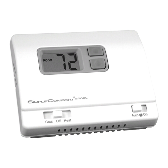
SC2000/SC2001
Non-Programmable Electronic Thermostats
• Controls Single Stage Heating/
Cooling Systems
• Single Stage Heat Pump
Systems
• Compatible with Gas, Oil or
Electric Systems
• Millivolt and Hydronic (water or
steam) System Compatible
• Mercury-Free, Environmentally
Safe
Advertisement
Table of Contents

Related Manuals for ICM Controls SC2000L


Summary of Contents for ICM Controls SC2000L
- Page 1 SC2000/SC2001 Non-Programmable Electronic Thermostats • Controls Single Stage Heating/ Cooling Systems • Single Stage Heat Pump Systems • Compatible with Gas, Oil or Electric Systems • Millivolt and Hydronic (water or steam) System Compatible • Mercury-Free, Environmentally Safe Installation, Operation & Application Guide For more information on our complete range of American-made products – plus wiring diagrams, troubleshooting tips and more, visit us at www.icmcontrols.com...
-
Page 2: Table Of Contents
Table of Contents Parts Diagram ..........................1 Specifications ..........................2 Important Safety Information ..................... 2 Package Contents/Tools Required ....................3 General Description ........................3 To Remove Existing Thermostat ....................4 To Install Thermostat ........................4 Installing and Changing Batteries ....................6 Replacing Wiring Labels ...................... -
Page 3: Parts Diagram
Parts Diagrams SC2000 SC2001 Battery RH RC Non HP – HP Reset Switch Non HP – HP Compartment Switch Jumper Jumper NON HP–HP NON HP–HP SC2000 RH RC SC2001 RH RC ELEC ELEC Electric/Gas Mode High Temp. Freeze Electric/Gas Mode High Temp. -
Page 4: Specifications
Specifications SC2000 SC2001 Input: Input: • Voltage: Millivolt to 30 VAC/VDC • Voltage: 18-30 VAC • DC Power: 3 volts (2 “AA” alkaline batteries included) Output: • Maximum: 1 amp per terminal (3 amp total for all terminals) • Temperature control ranges: 45°F to 90°F Accuracy: ± 1°F •... -
Page 5: Package Contents/Tools Required
Package Contents/Tools Required Package includes: SimpleComfort ® non-programmable thermostat on base, thermostat cover, wiring labels, screws and wall anchors, batteries (if applicable), Installation, Operation and Application Guide. Tools required for installation: Drill with 3/16” bit, hammer, screwdriver. General Description • The SimpleComfort ® thermostat is a digital, mercury-free, non-programmable, electronic thermostat •... -
Page 6: To Remove Existing Thermostat
To Remove Existing Thermostat ELECTRICAL SHOCK HAZARD – Turn off power at the main service panel by removing the fuse or switching the appropriate circuit breaker to the OFF position before removing the existing thermostat. 1. Turn off power to the heating and cooling system by removing the fuse or switching off the appropriate circuit breaker. 2. Remove cover of old thermostat. This should expose the wires. 3. - Page 7 To Install Thermostat (continued) Move the FAN AUTO/ON switch to AUTO. To remove cover, insert and twist a coin or screwdriver in the slots on the top of the thermostat. Put thermostat base against the wall where you plan to mount it (Be sure wires will feed through the wire opening in the base of the thermostat).
-
Page 8: Installing And Changing Batteries
Installing and Changing Batteries (SC2000 only) If your LCD is blank, or displaying LO BAT, the batteries are not installed or need to be changed. We suggest you change the batteries at least once a year, or whenever the LO BAT warning displays. Note: After installing new batteries, you have to reset the room temperature setting and the differential setting. -
Page 9: Sc2000 Wiring Diagrams
SC2000 Wiring Diagrams Zone Valve/Damper Motor Systems 3-Wire, Zone Valve/Damper Motor System RH RC W Y B O G RH RC W Y B O G RH RC W Y B O G 24 VAC * Use appropriate size, single pole/ double throw relay Zone 1 Zone 2... - Page 10 SC2000 Heating/Cooling 4-Wire, Single Transformer 5-Wire, Two Transformer RH RC RH RC Remove Pre-Installed Jumper Pre-Installed Jumper Transformer 120 VAC 24 VAC 120 VAC 24 VAC (Heating) Transformer Heating Heating Control Control Cooling Cooling Control Control 120 VAC 24 VAC Control Control (Cooling)
- Page 11 SC2000 Heating Only 3-Wire, Single Transformer 2-Wire, Single Transformer or Millivolt RH RC RH RC Pre-Installed Jumper Pre-Installed Jumper Transformer 120 VAC 24 VAC Thermopile Transformer Heating Heating Control Control Control...
- Page 12 SC2000 Heat Pump Cool Only Cool Active Heat Active 3-Wire, Reversing Valve Reversing Valve Single Transformer RH RC RH RC RH RC Pre-Installed Jumper Pre-Installed Jumper Pre-Installed Jumper Transformer Transformer Transformer 120 VAC 24 VAC 120 VAC 24 VAC 120 VAC 24 VAC Compressor Compressor...
-
Page 13: Sc2001 Wiring Diagrams
SC2001 Wiring Diagrams Heating and Cooling 4 or 5-Wire, Single Transformer Transformer 120 VAC 24 VAC (Optional) Heating Control Cooling Control Control... - Page 14 SC2001 Heating Only 4-Wire, Single Transformer 3-Wire, Single Transformer Transformer Transformer 120 VAC 24 VAC 120 VAC 24 VAC Heating Heating Control Control Control...
- Page 15 SC2001 Heat Pump Cooling Only Cool Active Heat Active 4-Wire Reversing Valve Reversing Valve Single Transformer Transformer Transformer Transformer 120 VAC 24 VAC 120 VAC 24 VAC 120 VAC 24 VAC Compressor Compressor Cooling Control Contactor Contactor Reversing Valve Reversing Valve Relay Relay...
-
Page 16: A Quick Test
A Quick Test CAUTION!: Do not switch system to cool if the temperature is below 50°F. This can damage the air conditioning system and may cause personal injury. Do not short jumper across terminals on the gas valve or at the system control to test installation. Action: Set the Cool/Off/Heat switch to Cool. Press the button until the temperature setting is 3°F below the room temperature. -
Page 17: Operation
Operation Setting the Room Temperature (Setpoint Temperature) Step 1: Press one of the arrow buttons; the current temperature setting displays. Step 2: Press the arrow button until the desired temperature setting displays. The new temperature setting is automatically saved. After 5 seconds, the display returns to showing the current room temperature. -
Page 18: Troubleshooting
Troubleshooting Symptom Remedy The system isn’t turning on Check the wiring (see Installation, Page 4) Check the batteries (SC2000 only) LCD is blank, or displaying “LO BAT” SC2000: Replace batteries, or make sure the existing ones are properly installed (see Installing and Changing Batteries, Page 6) SC2001: Verify 24 VAC is at thermostat. - Page 20 ONE-YEAR LIMITED WARRANTY The Seller warrants its products against defects in material or workmanship for a period of one (1) year from the date of manufacture. The liability of the Seller is limited, at its option, to repair, replace or issue a non-case credit for the purchase prices of the goods which are provided to be defective.