Table of Contents
Advertisement
• Configurable
• 2-Stage Heat/1-Stage Cool Systems
• Heat Pump Systems
• Backlit Display
• Field Temperature Calibration
• Filter Check
• Status Indicator Light
• Relay Outputs
(minimum voltage drop in thermostat)
• Ideally Suited for:
–
Residential (New Construction/Replacement)
–
Light Commercial
Installation, Operation & Application Guide
For more information on our complete range of American-made
products – plus wiring diagrams, troubleshooting tips and more,
visit us at www.icmcontrols.com
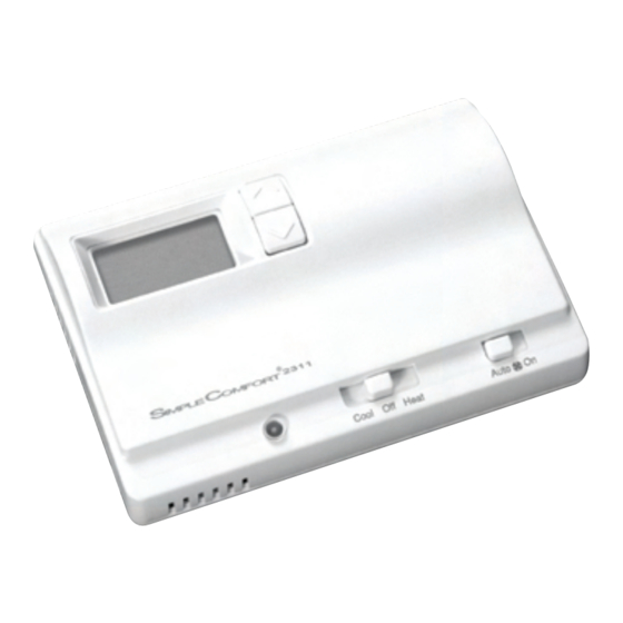
SC 231 1
Non-Programmable Electronic Thermostat
2 Heat/1 Cool
Manual Changeover
Hardwired
Advertisement
Table of Contents

Related Manuals for ICM Controls SC 2311


Summary of Contents for ICM Controls SC 2311
- Page 1 SC 231 1 2 Heat/1 Cool Manual Changeover Hardwired Non-Programmable Electronic Thermostat • Configurable • 2-Stage Heat/1-Stage Cool Systems • Heat Pump Systems • Backlit Display • Field Temperature Calibration • Filter Check • Status Indicator Light • Relay Outputs (minimum voltage drop in thermostat) • Ideally Suited for: – Residential (New Construction/Replacement) – Light Commercial Installation, Operation & Application Guide For more information on our complete range of American-made products –...
-
Page 2: Table Of Contents
Table of Contents Parts Diagram ..........................1 Specifications ..........................2 Important Safety Information .....................2 Package Contents/Tools Required ....................2 To Remove Existing Thermostat ....................3 To Install Thermostat ........................3 Terminal Designator Descriptions....................5 SC2311 Output Chart........................5 Wiring Diagrams ..........................6 Wiring Diagram Conversions .......................9 Configuration Mode ........................19 Testing the Thermostat ......................22 Mode of Operation ........................23 Operating Modes ........................24... -
Page 3: Parts Diagram
Parts Diagram Y W2 E... -
Page 4: Specifications
Specifications Electrical rating: • 24 VAC (18-30 VAC) • 1 amp maximum per terminal • 4 amp maximum total load Temperature control range: 45°F to 90°F (7°C to 32°C) Accuracy: ± 1°F (± 0.5°C) System configurations: 2-stage heat, 1-stage cool, heat pump, gas, oil, electric Timing: Anti-short Cycle: 5 minutes Backlight Operation: 13 seconds after mode change or button press Terminations: R, C, W1/O/B, Y, W2, E, G... -
Page 5: To Remove Existing Thermostat
To Remove Existing Thermostat ELECTRICAL SHOCK HAZARD – Turn off power at the main service panel by removing the fuse or switching the appropriate circuit breaker to the OFF position before removing the existing thermostat. 1. Turn off power to the heating and cooling system by removing the fuse or switching off the appropriate circuit breaker. 2. Remove cover of old thermostat. This should expose the wires. 3. - Page 6 To Install Thermostat (continued) To remove cover, insert and twist a coin or screwdriver in the slots on the sides of the thermostat. Put thermostat base against the wall where you plan to mount it (Be sure wires will feed through the wire opening in the base of the thermostat).
-
Page 7: Terminal Designator Descriptions
Terminal Designator Descriptions R – 24 VAC hot C – 24 VAC common W1/O/B – Configurable W1 – 1st stage heat for non-hp systems O – cool active reversing valve B – heat active reversing valve Y – 1st stage cool, 1st stage heat for heat pumps W2 –... -
Page 8: Wiring Diagrams
Wiring Diagrams First Heating Control First First Cooling Control Cooling Control Second Heating Control Control Control... - Page 9 Single Transformer Single Transformer First First Heating Control Heating Control Second Second Heating Control Heating Control Control...
- Page 10 Single Compressor Reversing Valve Compressor Stage Heat Emergency Heat Control...
-
Page 11: Wiring Diagram Conversions
Wiring Diagram Conversions SimpleComfort 2311 Electronic Thermostat Conversion to: ® Carrier Split Stream Condensers and Heat Pump Systems SC 231 1 Note 1: L terminal on PCB capped Electronic Thermostat Note 2: W3 terminal on PCB capped 24 VAC, return 24 VAC, common Reversing valve (cooling mode) Compressor contactor 2nd stage heating circuit Fan contactor circuit... - Page 12 SimpleComfort 2311 Electronic Thermostat Conversion to: ® Coleman 3000 Series Heat Pump Systems SC 231 1 Note 1: L terminal on PCB capped Electronic Thermostat Note 2: W3 terminal on PCB capped 24 VAC, return 24 VAC, common Reversing valve (cooling mode) Compressor contactor 2nd stage heating circuit Fan contactor circuit Emergency heating circuit...
- Page 13 SimpleComfort 2311 Electronic Thermostat Conversion to: ® ComfortMaker CYC Series Heat Pump Systems SC 231 1 Note 1: W2 terminal on PCB capped Electronic Thermostat Note 2: X terminal on PCB capped 24 VAC, return 24 VAC, common Reversing valve (cooling mode) Compressor contactor 2nd stage heating circuit Fan contactor circuit Outdoor thermostat...
- Page 14 SimpleComfort 2311 Electronic Thermostat Conversion to: ® Heil-Quaker 867.814 Series and PH50 Series Heat Pump Systems SC 231 1 Note 1: W2 terminal on PCB capped Electronic Thermostat 24 VAC, return 24 VAC, common Reversing valve (cooling mode) Compressor contactor 2nd stage heating circuit (sequencer 1) Fan contactor circuit 3rd stage heating circuit (sequencer 2) (capped)
- Page 15 SimpleComfort 2311 Electronic Thermostat Conversion to: ® Payne Reliant and Endura Model Heat Pump Systems SC 231 1 Note 1: L terminal on PCB capped Electronic Thermostat Note 2: W3 terminal on PCB capped 24 VAC, return 24 VAC, common Reversing valve (cooling mode) Compressor contactor 2nd stage heating circuit Fan contactor circuit...
- Page 16 SimpleComfort 2311 Electronic Thermostat Conversion to: ® Rheem/Ruud: -PGB, -PFA, -PCB, -PLA, and -PKA Series Heat Pump Systems SC 231 1 Note 1: L terminal on PCB capped Electronic Thermostat 24 VAC, return 24 VAC, common Reversing valve (heating mode) Compressor contactor 2nd stage heating circuit Fan contactor circuit Emergency heating circuit System monitor LED...
- Page 17 SimpleComfort 2311 Electronic Thermostat Conversion to: ® Goodman, Janitrol, Trane/American Standard Heat Pumps SC 231 1 Note 1: X2 terminal on PCB capped Electronic Thermostat Note 2: T terminal on PCB capped 24 VAC, return 24 VAC, common Reversing valve (cooling mode) Compressor contactor 2nd stage heating circuit Fan contactor circuit (capped)
- Page 18 SimpleComfort 2311 Electronic Thermostat Conversion to: ® York E1CS, E1FB, E1FH Heat Pump Systems SC 231 1 Note 1: X terminal on PCB capped Electronic Thermostat 24 VAC, return 24 VAC, common Reversing valve (cooling mode) Compressor contactor 2nd stage heating circuit Fan contactor circuit System monitor LED (capped)
- Page 19 SimpleComfort 2311 Electronic Thermostat Conversion to: ® Lennox CB19 Heat Pump Systems SC 231 1 Note 1: L terminal on PCB capped Electronic Thermostat 24 VAC, return 24 VAC, common Reversing valve (cooling mode) Compressor contactor 2nd stage heating circuit Fan contactor circuit Emergency heating circuit System monitor LED (capped)
- Page 20 SimpleComfort 2311 Electronic Thermostat Conversion to: ® Lennox HP19 and HP20 Heat Pump Systems SC 231 1 Electronic Thermostat 24 VAC, return V-VR 24 VAC, common Reversing valve (cooling mode) Compressor contactor 2nd stage heating circuit (sequencer 1) Fan contactor circuit Emergency heating circuit...
-
Page 21: Configuration Mode
Configuration Mode The configuration mode is used to set the SC2311 to match your heating/cooling system. The SC2311 functions with heat pump, air conditioning, gas, oil or electric heat systems. To configure the SC2311, perform the following steps: 1. Remove the cover of the thermostat by gently pulling on one of the corners. 2. - Page 22 3. Reversing Valve (O-Active or B-Active) – (Appears for REMOTE heat pump systems only) Change between “o” (O-Active) and “b” (B-Active). ROOM Press the button to set reversing valve setting. DIFF Press the SW6 button to advance to the next screen. FILTER 4. Temperature Scale (F or C) – Choose Fahrenheit or Celsius. REMOTE Press the button to select.
- Page 23 Maximum Heat Setpoint (55°F to 90°F) (13°C to 32°C) REMOTE REMOTE Adjust to control the maximum Heat set temperature allowed. ROOM ROOM Press the button to select. DIFF DIFF Press the SW6 button to advance to the next screen. FILTER FILTER Room temperature offset (+9°F to -9°F) (+4.5°C to -4.5°C) Adjust to calibrate displayed room temperature to match actual room temperature.
-
Page 24: Testing The Thermostat
Testing the Thermostat Once the thermostat is installed, it should be thoroughly tested. CAUTION!: Do not energize the air conditioning system when the outdoor temperature is below 50 degrees. It can result in equipment damage or personal injury. Cool Test 1. Slide Mode switch to Cool mode. 2. Adjust set temperature so it is 5 degrees below room temperature. 3. Air conditioning should come on within a few seconds. Status indicator may come on. Cool Off Heat 4. -
Page 25: Mode Of Operation
(Testing the thermostat continued from Page 22) Fan Test 1. Slide Fan switch to On position. 3. Slide Fan switch to Auto position. 2. Indoor fan turns on. 4. Indoor fan turns off. Auto Auto Mode of Operation The SC2311 is a two-stage heat, one-stage cool thermostat. It functions with air conditioning, heat pumps, gas, oil or electric heat. -
Page 26: Operating Modes
Operating Mode These are the possible operating modes of the SC2311. Off Mode In off mode, the thermostat will not turn on the heating or cooling appliances. Note 1: The indoor fan can be activated in every mode by sliding the Auto/On fan to the On position. Note 2: Off mode in used to enter the configuration setup (by pressing SW5 and SW6 simultaneously for 5 seconds). -
Page 27: Troubleshooting
Troubleshooting Symptom Remedy No display Check for 24 VAC at thermostat; display is blank when 24 VAC is not present System fan does not come on Verify wiring is correct properly Check configuration (see “Configuration Mode,” Setting 2, Page 19) See “Fan Test”... - Page 28 ONE-YEAR LIMITED WARRANTY The Seller warrants its products against defects in material or workmanship for a period of one (1) year from the date of manufacture. The liability of the Seller is limited, at its option, to repair, replace or issue a non-case credit for the purchase prices of the goods which are provided to be defective.