Table of Contents
Advertisement
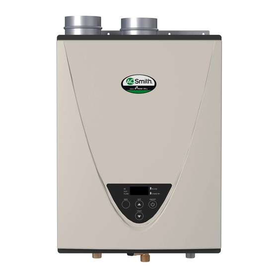
On-Demand Water Heater
Installation Manual and Owner's Guide
Gas Tankless Water Heater
Suitable for potable water heating and space-heating
Please refer to local codes for space-heating compliance.
FEATURING
•
ENDLESS HOT WATER
•
ON-DEMAND USAGE
•
COMPACT, SPACE SAVING
•
ENERGY CONSERVATION
•
COMPUTERIZED SAFETY
•
NO PILOT LIGHT
•
Satisfies the 2012 SCAQMD Rule
1146.2 for Ultra-Low NOx
Emissions
•
EASY-LINK SYSTEM AND
MULTI-UNIT SYSTEM
(540 (T-H3) model only)
Downloaded from http://GadgetsGo.com Authorized Dealer
ANSI Z21.10.3 and CSA 4.3
• 240 Indoor (T-H3J-DV)
• 340 Indoor (T-H3S-DV)
• 540 Indoor (T-H3-DV)
540 (T-H3)
model only
TM
Models
• 240 Outdoor (T-H3J-OS)
• 340 Outdoor (T-H3S-OS)
• 540 Outdoor (T-H3-OS)
If the information in these
instructions is not followed
exactly, a fire or explosion may
result causing property damage,
WARNING
personal injury or death.
- Do not store or use gasoline or other
flammable vapors and liquids in the vicinity
of this or any other appliance.
- WHAT TO DO IF YOU SMELL GAS
• Do not try to light any appliance.
• Do not touch any electric switch, do not
use any phone in your building.
• Immediately call your gas supplier from
a neighbor's phone. Follow the gas
supplier's instructions.
• If you cannot reach your gas supplier, call
the fire department.
- Installation and service must be performed
by a qualified installer, service agency or the
gas supplier.
If you have any questions, please
call or write to:
500 Tennessee Waltz Parkway
Ashland City, TN 37015
Toll Free: 1-877-737-2840
Advertisement
Table of Contents

Related Manuals for A.O. Smith T-H3S-DV


Summary of Contents for A.O. Smith T-H3S-DV
- Page 1 On-Demand Water Heater Installation Manual and Owner’s Guide ANSI Z21.10.3 and CSA 4.3 Models • 240 Indoor (T-H3J-DV) • 240 Outdoor (T-H3J-OS) • 340 Indoor (T-H3S-DV) • 340 Outdoor (T-H3S-OS) • 540 Indoor (T-H3-DV) • 540 Outdoor (T-H3-OS) 540 (T-H3) model only If the information in these instructions is not followed exactly, a fire or explosion may...
-
Page 2: Table Of Contents
Contents CONTENTS Installation Manual SPECIFICATIONS .......................... 4 INTRODUCTION .......................... 5 SAFETY GUIDELINES ........................6 INSTALLATION ..........................7 General.............................7 Clearances..........................9 Included accessories........................9 Optional items..........................9 Warning for installations......................11 High-altitude installations......................12 Venting instructions.......................13 Gas supply and gas pipe sizing....................25 Water connections........................27 Condensate drain........................28 Electrical connections......................30 Temperature remote controller....................31 Easy-Link System........................33... -
Page 3: Installation Manual
Installation Manual Installation Manual CONGRATULATIONS Congratulations and thank you for choosing our tankless water heater. Before use, we recommend that you read through this safety manual carefully. Please refer to the back of the manual for details about the warranty. Keep this manual for future reference. If you lose the manual, contact the manufacturer or your local distributor. -
Page 4: Specifications
Installation Manual Specifications SPECIFICATIONS Model Indoor Outdoor Indoor Outdoor Indoor Outdoor (T-H3J-DV) (T-H3J-OS) (T-H3S-DV) (T-H3S-OS) (T-H3-DV) (T-H3-OS) Natural Gas Input Min.: 15,000 Min.: 15,000 Min.: 15,000 BTU/h (Operating Range) Max.: 160,000 Max.: 180,000 Max.: 199,000 Propane Input Min.: 13,000 Min.: 13,000 Min.: 13,000 BTU/h (Operating Range) Max.: 160,000 Max.: 180,000 Max.: 199,000 Gas Connection 3/4"... -
Page 5: Introduction
• These high efficiency models have a built-in secondary heat exchanger that absorbs latent heat from the exhaust gas. • The 240 Indoor (T-H3J-DV), 340 Indoor (T-H3S-DV) and 540 Indoor (T-H3-DV) models are only to be installed indoors. The 240 Outdoor (T-H3J-OS), 340 Outdoor (T-H3S-OS) and 540 Outdoor (T-H3-OS) models are only to be installed outdoors. -
Page 6: Safety Guidelines
Installation Manual Safety Guidelines SAFETY GUIDELINES SAFETY DEFINITION Indicates an imminently hazardous situation which, if not avoided, will result in death or serious injury. DANGER Indicates an imminently hazardous situation which, if not avoided, could result in death or serious injury. WARNING Indicates an imminently hazardous situation which, if not avoided, could result in minor or moderate injury. -
Page 7: Installation
Regularly ensure that the area around the unit is dust- or debris-free. Regular maintenance is recommended for these types of environment. 9. The 240 Indoor (T-H3J-DV), 340 Indoor (T-H3S-DV), and 540 Indoor (T-H3-DV) are to be installed indoors only. These units are equipped with a thermistor and hi-limit switch for the exhaust gas, detecting excess temperatures within the flue and enabling the unit to safely stop operations if needed. - Page 8 Installation Manual Installation • Installation and service must be performed by a qualified installer (for example, a licensed plumber or gas fitter), otherwise the warranty will be void. WARNING • The installer (licensed professional) is responsible for the correct installation of the water heater and for compliance with all national, state / provincial, and local codes.
-
Page 9: Clearances
Front Side Bottom Model Bottom Front Back Sides 240 Indoor (T-H3J-DV) 12 in. 12 in. 4 in.* 0.5 in. 2 in. 340 Indoor (T-H3S-DV) (305 mm) (305 mm) (102 mm) (13 mm) (51 mm) 540 Indoor (T-H3-DV) 240 Outdoor (T-H3J-OS) 36 in. 12 in. 24 in. 0.5 in. 2 in. 340 Outdoor (T-H3S-OS) - Page 10 Installation Manual Installation 1. Temperature remote controller: 2. Pipe cover: 9008331005 (TH-PC03) 9008172005 (TM-RE40) The temperature remote controller has two functions. It allows the output temperature from the water heater to be adjusted within the range of 100 °F to 185 °F, and it also works as a diagnostic tool that will give a concise error code whenever there is a problem with the unit.
-
Page 11: Warning For Installations
Installation Manual Installation WARNING FOR INSTALLATIONS FOR YOUR SAFETY, READ BEFORE INSTALLATION: Do not install the heater where water, debris or Do not have the vent terminal pointing toward flammable vapors may get into the flue terminal. any opening into a building. Do not locate your This may cause damage to the heater and void the heater in a pit or location where gas and water warranty. -
Page 12: High-Altitude Installations
Installation Manual Installation HIGH-ALTITUDE INSTALLATIONS Check the elevation where your water heater is installed. Set DIPswitches shown in the table below depending on the altitude. Indoor models Altitude 0 to 2,000 ft. 2,000 to 3,000 to 5,000 to 7,500 to DIPswitches (DEFAULT) 3,000 ft. -
Page 13: Venting Instructions
Installation Manual Installation VENTING INSTRUCTIONS For the 240 Indoor (T-H3J-DV), 340 Indoor (T-H3S-DV) and 540 Indoor (T-H3-DV) models -General- • Improper venting of this appliance can result in excessive levels of carbon monoxide which can result in severe personal injury or death. - Page 14 3" venting 240 Indoor (T-H3J-DV) 540 Indoor (T-H3-DV) Vent length 340 Indoor (T-H3S-DV) (Upper bank of DIPswitches) ON 1 2 3 4 5 6 7 8 9 10 ON 1 2 3 4 5 6 7 8 5 to 20 ft.
- Page 15 Installation Manual Installation -Exhaust vent (ABS, PVC, CPVC, or polypropylene vent)- The Indoor models can be vented with ABS, PVC, CPVC, or polypropylene (temperature rated up to 149 °F). Vent material certified to ULC S636 standards is recommended in the USA. In Canada, plastic venting must be certified to ULC S636 standards. Item Material United States Canada Schedule 40 PVC ANSI/ASTM D1785 PVC-DWV ANSI/ASTM D2665 Exhaust pipe and Schedule 40 CPVC ANSI/ASTM F441...
- Page 16 Installation Manual Installation -Two-pipe, direct-vent illustrations- PVC, ABS, or polypropylene vent Typical installations using Vertical Installation Horizontal Installation Wall Hanger Roof Roof flashing Hanger Fire stop Connect between exhaust vent collar and piping. See the instructions below. For details of the optional items, refer to the Installation manual for each optional item. <How to install intake and exhaust venting (two-pipe, direct-vent) with the indoor models>...
- Page 17 Installation Manual Installation -Single pipe with room-air intake illustrations- Typical installations using PVC, ABS, or polypropylene vent Vertical Installation Horizontal Installation Wall Roof Hanger Roof flashing Elbow Fire stop Elbow Connect between exhaust vent collar and piping. See the instructions below. For details of the optional items, refer to the Installation manual for each Optional item. <How to install single vent with the indoor models>...
- Page 18 Installation Manual Installation -Exhaust vent (Stainless steel vent)- This is a Category IV appliance and must be vented accordingly. The vent system must be sealed airtight. All seams and joints without gaskets must be sealed with high heat resistant silicone sealant or UL listed aluminum adhesive tape having a minimum temperature rating of 160 °F. For best results, a vent system should be as short and straight as possible.
- Page 19 Installation Manual Installation -Direct-vent and single vent Illustrations- Typical installations using stainless steel vents Vertical Installation Horizontal Installation Wall Rain cap Roof Hanger Roof flashing Hanger Fire stop Sidewall vent termination • The diagram above shows direct-vent installations. For single vent installation, connect a 4" elbow directly on the intake vent collar instead of a straight pipe.
- Page 20 • For common-venting pieces and components, the manufacturer recommends Centrotherm's vent line. Allowable models for common-venting 240 Indoor (T-H3J-DV) 340 Indoor (T-H3S-DV) 540 Indoor (T-H3-DV) Only the models listed in the table above can be common-vented together. Different models cannot be common-vented.
- Page 21 Max. DIPswitch settings Vent Max. Vertical and No.of Diameter* Horizontal 240 Indoor (T-H3J-DV) 540 Indoor (T-H3-DV) water (Total) Vent Length** (L) (Upper bank of DIPswitches) 340 Indoor (T-H3S-DV) heaters 4 in. 25 ft. (7.6 m) (110 mm) 50 ft. (15.2 m) 5 in. (125 mm) 20 ft. (6.1 m) 100 ft. (30.5 m) 75 ft. (22.9 m) 6 in.
- Page 22 Installation Manual Installation -Vent termination clearances- INSIDE CORNER DETAIL Vent terminal Air supply inlet Area where is not permitted Gas meter / regulator Canada U.S.A Direct-vent and other Direct- Other than than Direct-vent vent Direct-vent Clearance above grade, veranda, porch, deck, or 1 foot 1 foot 1 foot...
- Page 23 Installation Manual Installation -For sidewall terminations- Please follow all local and national codes in regards to proper termination clearances. In the absence of such codes, the clearances below can be used as guidelines. Local codes supersede these guidelines. CAUTION For multiple sidewall exhaust terminations (e.g. Multi- 2 ft.
- Page 24 Installation Manual Installation Exhaust and/or direct-vent sidewall terminations should be at least 2 ft. (610 mm) away from an opposite surface/ wall. Do not place the termination directly in front of an opening into a building Exhaust termination 2 ft. (610 mm) min. -For rooftop terminations- Please follow all local and national codes in regards to proper termination clearances.
-
Page 25: Gas Supply And Gas Pipe Sizing
Installation Manual Installation GAS SUPPLY AND GAS PIPE SIZING -General- • Check that the type of gas matches the rating plate first. • Ensure that any and all gas regulators used are operating properly and providing gas pressures within the specified range shown below. Excess gas inlet pressure may cause serious accidents. - Page 26 Installation Manual Installation -Natural Gas Supply Piping- Maximum delivery Capacity of Cubic Feet of Gas per Hour of IPS Pipe carrying Natural Gas with 0.60 Specific Gravity. Based on Pressure Drop of 0.5" W.C. Based on Energy Content of 1,000 BTU/Cubic ft.: The water heater requires 160 Cubic ft./hr for the 240 (T-H3J) model, 180 Cubic ft./hr for the 340 (T-H3S) model, and 199 Cubic ft./hr for the 540 (T-H3) model. Unit: Cubic feet per hour Length Pipe Size...
-
Page 27: Water Connections
Installation Manual Installation -Measuring inlet gas pressure- 1. Turn off all electric power to the water heater if service is to be performed. 2. Turn the manual gas valve located on the outside of the unit clockwise to the off position. The water heater cannot perform properly without sufficient inlet gas pressure. -
Page 28: Condensate Drain
Installation Manual Installation -Pressure relief valve- The water heater has a high-temperature shutoff switch built in as a standard safety feature (called a Hi-Limit switch) therefore a “pressure only” relief valve is required. • This unit does not come with an approved pressure relief valve. •... - Page 29 Installation Manual Installation -Condensate Drain Connections- Discharge condensate (acidic water) in accordance with all local codes and common safety practices. WARNING The water heater is a high efficiency condensing water heater that produces condensate (acidic water). The acidic condensate generated in the secondary heat exchanger can be neutralized by the Neutralizer accessory.
-
Page 30: Electrical Connections
Installation Manual Installation • The condensate drain is at atmospheric pressure (non-pressurized) and therefore must be allowed to drain freely with gravity only. Please ensure that there are no blockages along the condensate drain tube. All portions of the WARNING condensate drain (neutralizer and drain tube) must be at a lower elevation than the water heater to prevent condensate water from building up inside the heat exchanger. -
Page 31: Temperature Remote Controller
Installation Manual Installation TEMPERATURE REMOTE CONTROLLER -Outdoor models only- Check that these items below are included with the remote controller. Temperature Screws Manual Remote controller cable remote controller Qty: 1 Qty: 2 Qty: 1 Qty: 1 -INSTALLATION- • This remote controller is NOT waterproof Do not install in high temperature environments, steamy conditions (such as a bathroom), outdoors, in direct sunlight, or within the reach of children. - Page 32 Installation Manual Installation 3. Tighten the two "Fork terminals" beneath the two "Remote controller terminal" screws on the back of the main body. (Fig. C-1) 4. Cut out the inlet for the remote controller cable from the bottom of the main body. (Fig. C-2) 5.
-
Page 33: Easy-Link System
Installation Manual Installation EASY-LINK SYSTEM (Available on the 540 (T-H3) model only) -General- The 540 (T-H3) model water heaters can be connected with allowable heaters (see the table below) with communication cables to work as a multiple-unit manifold system. • The Easy-Link System allows up to 4 units to manifold together. •... - Page 34 Installation Manual Installation 2. Select one unit to be the “PARENT” unit. 3. “PARENT” unit : Locate the two banks of DIPswitches at the bottom left of the computer board of the unit that you select to be the “PARENT” unit. Change DIPswitch No. 1 on the lower bank of DIPswitches to the ON position.
- Page 35 Installation Manual Installation • Either a temperature controller or a remote controller is required for the Easy- NOTICE Link System for ease of usage and maintenance. (C) Examples of incorrect settings and /or connections CASE 1: Wrong DIPswitch setting on the "PARENT" unit •...
- Page 36 Installation Manual Installation CASE 3: Wrong connections between the "CHILD-1" unit and the "CHILD-2" unit • If you connect the “PARENT” connector of the “CHILD-1” unit to the “1” connector of the “CHILD-2” unit, the “CHILD-2” unit will operate as an individual unit, and will not be part of the Easy-Link System.
-
Page 37: Multi-Unit System
Installation Manual Installation MULTI-UNIT SYSTEM Multiple 540 (T-H3) models can be combined for a Multi-Unit System, along with the multi-unit controller (Part 9008300005 (TM-MC02)). The multi-unit controller can control from 2 units to 20 units for commercial or residential applications. For a 20-unit system, the computer can modulate between the usages of 13,000 BTU/h (Propane) or 15,000 BTU/h (Natural gas) to 4.0 Million BTU/h. 9008300005 (TM-MC02) (T-H3) Hot Out Cold IN An individual cut-off switch is recommended for each unit in a Multi-Unit System for the purpose of maintenance. -
Page 38: Applications
Installation Manual Applications APPLICATIONS -Space-Heating Applications- • In order to purge air in water pipes within a closed-loop system, an air vent and air separator should be installed in the system. Required circulation flow rates are labeled next to each application diagram. These flow rate WARNING requirements must be followed. - Page 39 Installation Manual Installation -Dual-purpose hot water heating- (Domestic and Space Heating): Diagrammatic layout of radiant heating and domestic water heater per Mass. code. All water piping should be insulated in accordance with 780 CMR (Massachusetts energy code) 3-inch gas exhaust vent (Discharge must Cold water supply Automatic tempering device comply with local and must be installed below...
-
Page 40: Initial Operation
Installation Manual Initialial operation INITIAL OPERATION FOR YOUR SAFETY, READ BEFORE OPERATING • Check the GAS and WATER CONNECTIONS for leaks before firing unit for the first time. • Open the main gas supply valve to the unit using only your hand to avoid any spark. Never use tools. -
Page 41: Owner's Guide
Owner's Guide Operating Safety Owner's Guide CONGRATULATIONS Congratulations and thank you for choosing our tankless water heater. Before use, we recommend that you read through this safety manual carefully. Please refer to the back of the manual for details about the warranty. -
Page 42: Operating Safety
Owner's Guide Operating Safety OPERATING SAFETY FOR YOUR SAFETY READ BEFORE OPERATING WARNING: If you do not follow these instructions exactly, a fire or explosion may result causing property damage, personal injury or loss of life. A. This water heater does not have a pilot. It is equipped with an ignition device that automatically lights the burner. - Page 43 Owner's Guide Operating Safety DANGER Vapors from flammable liquids will explode and catch fire causing death or severe burns. Do not use or store flammable products such as gasoline, solvents or adhesives in the same room or area near the water heater. Keep flammable products: Vapors: 1.
-
Page 44: Normal Operation
Owner's Guide Normal Operation NORMAL OPERATION TEMPERATURE CONTROLLER and REMOTE CONTROLLER The illustration below shows an example of the controllers. The exact display may differ from examples. Temperature controller Remote controller Display for Temperature "INFO" Button When the STAND BY LED is ON, the hot water temperature will be Each time the button is pressed, displayed. -
Page 45: Temperature Settings
Owner's Guide Normal Operation TEMPERATURE SETTINGS -Set temperature Screen on the controller Operation Temperature controller Remote controller Turn on the 120 VAC power supply to the unit (the water heater or the multi-unit controller). Press the "ON/OFF" button on the controller in order to turn the controller on. When ON, the STAND BY LED is lit. It shows the set temperature on its display as shown in (EX.: 120 °F) the picture on the right. (EX.: 120 °F) -
Page 46: Additional Features
Owner's Guide Normal Operation ADDITIONAL FEATURES -Information mode- You can get some information about the water heater condition by pressing the "INFO" button. For more information, follow the procedures below: Screen on the controller Operation Temperature controller Remote controller Inlet water temperature First of all, inlet water temperature will be displayed on the controller by pressing the "INFO"... -
Page 47: Temperature Settings On The Pcb (Without Remote Controller)
Owner's Guide Normal Operation TEMPERATURE SETTINGS ON THE PCB (WITHOUT REMOTE CONTROLLER) There are 2 preset temperatures (120 °F (50 °C) and 140 °F (60 °C)) that you can select from by changing the DIPswitch settings on the computer board without the remote controller. See the table below. When the remote controller is in normal operation, the set temperature of the remote controller is given priority over the set temperature of the DIPswitch settings. -
Page 48: Flow
• The freeze protection system will activate when the surrounding and/or outside temperatures drop below 36.5 °F (2.5 °C). • For the 240 Indoor (T-H3J-DV), 340 Indoor (T-H3S-DV) and 540 Indoor (T-H3-DV) models: • In any areas subject to freezing temperatures, the manufacturer highly recommends an indoor installation with an indoor model. In such an installation, freezing issues can only occur if cold air enters through the venting into the heat exchanger, whether by negative pressures within the installation location or by strong outside winds. -
Page 49: Maintenance And Service
Owner's Guide Normal Operation MAINTENANCE AND SERVICE Turn off the electrical power supply and close the manual gas shutoff valve and the manual water control valve before servicing. WARNING • Clean the cold-water inlet filter. (Refer to the Unit Draining and Filter Cleaning Section in this page.) •... -
Page 50: Troubleshooting
Owner's Guide Troubleshooting TROUBLESHOOTING GENERAL PROBLEM SOLUTIONS It takes long time to • The time it takes to deliver hot water from the water heater to your get hot water at the fixtures depends on the length of piping between the two. The longer fixtures. - Page 51 Owner's Guide Troubleshooting PROBLEM SOLUTIONS Unit does not ignite • Is the flow rate over 0.5 GPM (1.9 L/min)? (p. 44) when water goes • Check for the filter on cold water inlet. (p. 49) through the unit. • Check for reverse connection and cross connection. • If you use the remote controller and/or temperature controller, is the power button turned on? •...
-
Page 52: Error Codes
Owner's Guide Troubleshooting ERROR CODES -General- • The units are self-diagnostic for safety and convenience when troubleshooting. • If there is a problem with the installation or the unit, the error code will be displayed on the temperature controller and remote controller. •... - Page 53 Owner's Guide Troubleshooting -Fault Analysis of Error Codes- If the error code is displayed on the computer board of the water heater or remote controller and/or temperature controller, please check the following. After checking, consult with the manufacturer. Green Malfunction Remote Diagnosis description...
- Page 54 Owner's Guide Troubleshooting Green Malfunction Remote Diagnosis description Two Times Air-fuel ratio rod • Check for connection/breakage of wires (Part #709) failure and/or soot on the AFR rod (Part #108). Two Times Flow sensor failure • Check for connection/breakage of wires and/or debris on the flow sensor impeller (Part #402). (Easy-Link System only) Six Times Abnormal main gas • Check for connection/breakage of wires (Part #708)
-
Page 55: Components Diagram
Owner's Guide Components Diagram COMPONENTS DIAGRAM Case assembly Outdoor models Indoor models Temperature controller Temperature Indoor models remote controller Page Downloaded from http://GadgetsGo.com Authorized Dealer... - Page 56 Owner's Guide Components Diagram Computer board assembly 240 (T-H3J) and 340 (T-H3S) models 540 (T-H3) model 707 722 Surge box assembly Page Downloaded from http://GadgetsGo.com Authorized Dealer...
- Page 57 Owner's Guide Components Diagram Burner assembly Burner assembly 109 111 Manifold assembly 540 (T-H3) model Page Downloaded from http://GadgetsGo.com Authorized Dealer...
- Page 58 Owner's Guide Components Diagram Water Way assembly 540 (T-H3) model 240 (T-H3J) and 340 (T-H3S) models Bypass section (540 (T-H3) model) Water outlet section Water inlet section Page Downloaded from http://GadgetsGo.com Authorized Dealer...
-
Page 59: Parts List
T-H3J, T-H3S and 540 models T-H3 models Case assembly for Indoor models EK159 for Outdoor models EK164 Front cover for 240 and 340 Indoor (T-H3J-DV and T-H3S-DV) 319143-505 EK187 for 240 and 340 Outdoor (T-H3J-OS and T-H3S-OS) 319143-506 EK188 for 540 Indoor (T-H3-DV) - Page 60 Owner's Guide Parts List Part # Item # Description 240, 340 and T-H3J, T-H3S and 540 models T-H3 models Pressure port 319143-042 EKK2D Combustion chamber tube 319143-344 EX019 Gas inlet 319143-455 EK117 Gas inlet ring 319143-342 EX00D Surge box plate 319143-522 EK163 O-ring P18 NBR (Black)
- Page 61 Owner's Guide Parts List Part # Item # Description 240, 340 and T-H3J, T-H3S and 540 models T-H3 models Fastener “16-25A” 319143-205 EKK39 Fastener “6-15” 319143-112 EX12K Flat heater 319143-535 EK217 Drain tube 319143-536 EK218 Cold pipe for 240 (T-H3J) and 340 (T-H3S) models 319143-537 EK219 for 540 (T-H3) model...
-
Page 62: Output Temperature Chart
Owner's Guide Output Temperature Chart OUTPUT TEMPERATURE CHART Chart is based on properly sized gas line 240 (T-H3J) model Output Temperature vs. GPM (Max. 6.6 GPM) with Various Inlet Water Temperature Set Temp. (°F) 340 (T-H3S) model Output Temperature vs. GPM (Max. 8.0 GPM) with Various Inlet Water Temperature Set Temp. -
Page 63: Limited Warranty
Owner's Guide Warranty LIMITED WARRANTY 1. The manufacturer warrants this product against defects in materials or workmanship as described in this document if installed within the United States or Canada. The manufacturer or its authorized Service Representative will, at its sole discretion, repair or replace any failed or defective mechanical or electrical parts, or components thereof, or, if the manufacturer or its authorized Service Representative cannot replace said parts, and repair is not commercially practicable, the manufacturer or its authorized Service Representative will refund the purchase price. - Page 64 Owner's Guide Warranty • Freeze damage that occurs without taking proper preventive measures as described in the installation manual. • Condensate damage due to improperly installed or lack of a condensate trap (drain). • Any product not installed in compliance with all applicable local & provincial codes, ordinances, and good trade practices. • Any product sold to or installed in areas outside of the fifty states (and the District of Columbia) of the United States of America and Canada. • Any product installed in applications that cause the water heater to activate more than 300 times per day. (This averages to an activation every 5 minutes in a 24-hour period.) • Any failures that are not due to defects in materials or workmanship (mechanical and/or electrical parts). • Damages due to improper installation: • Gas: incorrect gas pipe sizing, incorrect gas meter sizing, incorrect gas type, and/or gas pressures that fall outside the product’s specified range. • Water: incorrect water pipe sizing, water pressures that fall outside the product’s specified range, recirculation flow rates that fall outside the product’s specified range (air removal), and/or lack of proper methods of air removal in a closed-loop, circulation system.