Table of Contents
Advertisement
Quick Links
A75MD+/ A78MD Setup Manual
FCC Information and Copyright
This equipment has been tested and found to comply with the limits of a Class B
digital device, pursuant to Part 15 of the FCC Rules. These limits are designed
to provide reasonable protection against harmful interference in a residential
installation. This equipment generates, uses, and can radiate radio frequency
energy and, if not installed and used in accordance with the instructions, may
cause harmful interference to radio communications. There is no guarantee that
interference will not occur in a particular installation.
The vendor makes no representations or warranties with respect to the contents
here and specially disclaims any implied warranties of merchantability or fitness
for any purpose. Further the vendor reserves the right to revise this publication
and to make changes to the contents here without obligation to notify any party
beforehand.
Duplication of this publication, in part or in whole, is not allowed without first
obtaining the vendor's approval in writing.
The content of this user's manual is subject to be changed without notice and we
will not be responsible for any mistakes found in this user's manual. All the brand
and product names are trademarks of their respective companies.
Dichiarazione di conformità
sintetica
Ai sensi dell'art. 2 comma 3 del D.M.
275 del 30/10/2002
Si dichiara che questo prodotto è
conforme alle normative vigenti e
soddisfa i requisiti essenziali richiesti
dalle direttive
2004/108/CE, 2006/95/CE e
1999/05/CE
quando ad esso applicabili
Short Declaration of conformity
We declare this product is complying
with the laws in force and meeting all
the essential requirements as specified
by the directives
2004/108/CE, 2006/95/CE and
1999/05/CE
whenever these laws may be applied
Advertisement
Table of Contents

Related Manuals for Biostar A78MD


Summary of Contents for Biostar A78MD
- Page 1 A75MD+/ A78MD Setup Manual FCC Information and Copyright This equipment has been tested and found to comply with the limits of a Class B digital device, pursuant to Part 15 of the FCC Rules. These limits are designed to provide reasonable protection against harmful interference in a residential installation.
-
Page 2: Table Of Contents
Table of Contents Chapter 1: Introduction ...............1 Before You Start................. 1 Package Checklist ..............1 Motherboard Specifications ............2 Rear Panel Connectors ............. 3 Motherboard Layout ..............4 Chapter 2: Hardware Installation ..........5 Install Central Processing Unit (CPU) ........5 Install a Heatsink ............... -
Page 3: Chapter 1: Introduction
A75MD+/A78MD CHAPTER 1: INTRODUCTION 1.1 Before You Start Thank you for choosing our product. Before you start installing the motherboard, please make sure you follow the instructions below: Prepare a dry and stable working environment with sufficient lighting. Always disconnect the computer from power outlet before operation. -
Page 4: Motherboard Specifications
1x Serial Port Header Form Factor microATX Form Factor, 226 mm x 174 mm Windows XP / 7 / 8 / 8.1 OS Support Biostar reserves the right to add or remove support for any OS with or without notice. -
Page 5: Rear Panel Connectors
A75MD+/A78MD 1.4 Rear Panel Connectors Note 1: DVI-D / VGA Output require an AMD family processor with intedrated graphics. Note 2: The mainboard supports two independent display outputs. Note 3: Since the audio chip supports High Definition Audio Specification, the function of each audio jack can be defined by software. -
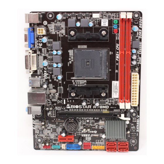
Page 6: Motherboard Layout
Motherboard Manual 1.5 Motherboard Layout Note: ■ represents the 1st pin. -
Page 7: Chapter 2: Hardware Installation
A75MD+/A78MD CHAPTER 2: HARDWARE INSTALLATION 2.1 Install Central Processing Unit (CPU) Step 1: Locate the CPU socket on the motherboard Step 2: Pull the socket locking out from the socket and then raise the lever up to a 90-degree angel. -
Page 8: Install A Heatsink
Motherboard Manual Step 4: Hold the CPU down firmly, and then close the lever to locked the position 2.2 Install a Heatsink Step 1: Place the heatsink and fan assembly onto the retention frame. Match the heatsink clip with the socket mounting-lug. Hook the spring clip to the mounting-lug. -
Page 9: Connect Cooling Fans
A75MD+/A78MD 2.3 Connect Cooling Fans These fan headers support cooling-fans built in the computer. The fan cable and connector may be different according to the fan manufacturer. Connect the fan cable to the connector while matching the black wire to pin#1. -
Page 10: Install System Memory
Motherboard Manual 2.4 Install System Memory A. DDR3 Modules Step 1: Unlock a DIMM slot by pressing the retaining clips outward. Align a DIMM on the slot such that the notch on the DIMM matches the break on the slot. Step 2: Insert the DIMM vertically and firmly into the slot until the retaining clips snap back in place and the DIMM is properly seated. - Page 11 A75MD+/A78MD B. Memory Capacity DDR3 Module DIMM Socket Location Total Memory Size DDR3_A1 512MB/1GB/2GB/4GB/8GB/16GB Max is 32GB. DDR3_B1 512MB/1GB/2GB/4GB/8GB/16GB C. Dual Channel Memory Installation Please refer to the following requirements to activate Dual Channel function: Install memory module of the same density in pairs, shown in the table.
-
Page 12: Expansion Slots
Motherboard Manual 2.5 Expansion Slots PEX16_1: PCI-Express Gen3 x16 Slot PCI-Express 3.0 compliant. Maximum theoretical realized bandwidth of 16GB/s simultaneously per direction, for an aggregate of 32GB/s totally. Only FM2+ processors can support PCIe 3.0. PEX1_1: PCI-Express Gen2 x1 Slot PCI-Express 2.0 compliant. -
Page 13: Jumper Setting
A75MD+/A78MD 2.6 Jumper Setting The illustration shows how to set up jumpers. When the jumper cap is placed on pins, the jumper is “close”, if not, that means the jumper is “open”. Pin opened Pin closed Pin1-2 closed JCMOS1: Clear CMOS Header Placing the jumper on pin2-3, it allows user to restore the BIOS safe setting and the CMOS data. -
Page 14: Headers & Connectors
Motherboard Manual 2.7 Headers & Connectors ATXPWR1: ATX Power Source Connector For better compatibility, we recommend to use a standard ATX 24-pin power supply for this connector. Make sure to find the correct orientation before plugging the connector. Assignment Assignment +3.3V +3.3V -12V... - Page 15 A75MD+/A78MD JPANEL1: Front Panel Header This 16-pin header includes Power-on, Reset, HDD LED, Power LED, and speaker connection. It allows user to connect the PC case’s front panel switch functions. Assignment Function Assignment Function Speaker Connector Speaker Power LED (+)
- Page 16 Motherboard Manual JFRONT_USB3_1: Header for USB 3.0 Ports at Front Panel This header allows user to add additional USB ports on the PC front panel, and also can be connected with a wide range of external peripherals. Assignment Assignment VBUS0 SSRX1- SSRX1+ Ground...
- Page 17 A75MD+/A78MD F_AUDIO1: Front Panel Audio Header This header allows user to connect the front audio output cable with the PC front panel. This header supports HD and AC’97 audio front panel connector. HD Audio AC’97 Assignment Assignment Mic Left in...
-
Page 18: Chapter 3: Uefi Bios & Software
BIOS Update Utility, BIOS Online Update Utility and BIOS Flasher. 1. BIOS Update Utility 1. Installing BIOS Update Utility from the DVD Driver. Download the proper BIOS from www.biostar.com.tw 3. Open BIOS Update Utility and click the Update BIOS button on the main screen. - Page 19 A75MD+/A78MD 6. After the BIOS Update process is finished, click on OK to reboot the system. 7. While the system boots up and the full screen logo shows up, please press <Delete> key to enter BIOS setup. After entering the BIOS setup, please go to the Save & Exit, using the Restore Defaults function to load Optimized Defaults, and select Save Changes and Reset to restart the computer.
- Page 20 Motherboard Manual 2. Online Update Utility 1. Installing BIOS Update Utility from the DVD Driver. 2. Please make sure the system is connected to the internet before using this function. 3. Open BIOS Update Utility and click the Online Update button on the main screen.
- Page 21 Note2: Shutting down or resetting the system while updating the BIOS will lead to system boot failure. The BIOSTAR BIOS Flasher is built in the BIOS ROM. To enter the utility, press <F12> during the Power-On Self Tests (POST) procedure while booting up.
- Page 22 Motherboard Manual 6. Select the proper BIOS file, and a message asking if you are sure to flash the BIOS file. Click Yes to start updating BIOS. 7. A dialog pops out after BIOS flash is completed, asking you to restart the system.
-
Page 23: Software
A75MD+/A78MD 3.3 Software Installing Software 1. Insert the Setup DVD to the optical drive. The driver installation program would appear if the Autorun function has been enabled. 2. Select Software Installation, and then click on the respective software title. 3. Follow the on-screen instructions to complete the installation. - Page 24 Note2: If you are not using Outlook Express as your default e-mail client application, you may need to save the system information to a .txt file and send the file to our tech support with other e-mail application. Go to the following web http://www.biostar.com.tw/app/en/about/contact.php for getting our contact information.
- Page 25 A75MD+/A78MD BIOScreen Utility This utility allows you to personalize your boot logo easily. You can choose BMP as your boot logo so as to customize your computer. Please follow the step-by-step instructions below to update boot logo: Load Image:Choose the picture as the boot logo.
-
Page 26: Chapter 4: Useful Help
Motherboard Manual CHAPTER 4: USEFUL HELP 4.1 Driver Installation After you installed your operating system, please insert the Fully Setup Driver DVD into your optical drive and install the driver for better system performance. You will see the following window after you insert the DVD The setup guide will auto detect your motherboard and operating system. -
Page 27: Ami Bios Beep Code
A75MD+/A78MD 4.2 AMI BIOS Beep Code Boot Block Beep Codes Number of Beeps Description Continuing Memory sizing error or Memory module not found POST BIOS Beep Codes Number of Beeps Description Success booting. Display memory error (system video adapter) 4.3 Troubleshooting... -
Page 28: Raid Functions
Motherboard Manual CPU Overheated If the system shutdown automatically after power on system for seconds, that means the CPU protection function has been activated. When the CPU is over heated, the motherboard will shutdown automatically to avoid a damage of the CPU, and the system may not power on again. In this case, please double check: The CPU cooler surface is placed evenly with the CPU surface. - Page 29 A75MD+/A78MD RAID 1: Data are stored twice by writing them to both the data disk (or set of data disks) and a mirror disk (or set of disks). If a disk fails, the controller uses either the data drive or the mirror drive for data recovery and continues operation.
-
Page 30: Amd Dual Graphics Technology
Motherboard Manual 4.5 AMD DUAL Graphics Technology AMD Dual Graphics Technology Introduction When user adds a PCIE display adapter, it can be integrated with IGD to show better performance. To make the two video devices work simultaneously and normally, please refer to the following setting. AMD Dual Graphics Requirement Operating System: Windows 7 / Windows 8 Supported Dual Graphics Combinations:... - Page 31 A75MD+/A78MD AMD Dual Graphics Setup Step 1: Insert Dual Graphics-Ready graphics card into PEX16_1 slot. Step 2: Set the BIOS setting as follows: [Chipset]→[North Bridge]→[GFX Configuration] →[Surround View]→[Enabled] Step 3: Install Driver DVD Chipset Driver, and reboot the system. Activate AMD VISION Engine Control Center to make sure CrossFire has been enabled.
-
Page 32: Appendix: Specifications In Other Languages
اﻟﻤﻌﺎﻟﺞ اﻟﺤﺪ اﻷﻗﺼﻰ ﻟﻠﻄﺎﻗﺔ اﻟﺤﺮارﻳﺔ ﻓﻲ ﺗﺼﻤﻴﻢ thermal design power اﻟﻤﺮآﺰﻳﺔ ﺋﻤﺔ دﻋﻢ اﻟﻤﻌﺎﻟﺞ ﻟﻘﺎ ﻳﺮﺟﻰ اﻟﺮﺟﻮع إﻟﻰ اﻟﻤﻮﻗﻊ www.biostar.com.tw A75MD+: AMD A75 FCH ﻣﺠﻤﻮﻋﺔ اﻟﺸﺮاﺋﺢ A78MD: AMD A78 FCH 2400(OC)/ 2133 1866 1600 1333 1066 DDR3 . ار دي... - Page 33 A75MD+/A78MD اﻟﻤﻮاﺻﻔﺎت اﻟﺜﺎﻧﻴﺔ ﺟﻴﺠﺎﺑﺎﻳﺖ x SATA وﺻﻠﺔ آﻞ ﻣﻮزع ﻳﺘﺤﻤﻞ ﻓﺘﺤﺘﻴﻦ ﻧﺎﻗﻞ ﻣﺘﺴﻠﺴﻞ ﻋﺎم ﻧﺎﻗﻞ ﻣﺘﺴﻠﺴﻞ ﻋﺎم ﻣﻮزع آﻞ ﻣﻮزع ﻳﺘﺤﻤﻞ ﻓﺘﺤﺘﻴﻦ ﻧﺎﻗﻞ ﻣﺘﺴﻠﺴﻞ ﻋﺎم ﻧﺎﻗﻞ ﻣﺘﺴﻠﺴﻞ ﻋﺎم ﻣﻮزع دﺑﺎﺑﻴﺲ ﻣﻮﺻﻠﺔ ﻟﻠﻄﺎﻗﺔ دﺑﻮس وﺻﻠﺔ ﻟﻠﻄﺎﻗﺔ اﻟﻤﺪاﺧﻞ واﻟﻤﺨﺎرج ﻣﺮوﺣﺔ ﺗﺒﺮﻳﺪ وﺣﺪة اﻟﻤﻌﺎﻟﺠﺔ اﻟﻤﺮآﺰﻳﺔ...
-
Page 34: French
Centrale. A75MD+: AMD A75 FCH Jeu de puces A78MD: AMD A78 FCH Supporte mémoire DDR3 double canal 800/ 1066/ 1333/ 1600/ 1866/ 2133/ 2400(OC)/ 2600(OC) Banc de mémoire 2 x DDR3 DIMM, Supporte max. jusqu’à une mémoire de 32 GB Mémoire... - Page 35 1x Embase port série Facteur Facteur d'encombrement microATX, 226 mm x 174 mm d'encombrement Windows XP / 7 / 8 / 8.1 Support SE Biostar se réserve le droit d’ajouter ou d'enlever le support pour toute SE avec ou sans préavis.
-
Page 36: German
* Bitte konsultieren Sie für CPU-Unterstützungsliste A75MD+: AMD A75 FCH Chipset A78MD: AMD A78 FCH Unterstützt zweikanaliges DDR3 800/ 1066/ 1333/ 1600/ 1866/ 2133/ 2400(OC)/ 2600(OC) 2 x DDR3 DIMM-SpeicherSlot, Max. Uterstützung bis zu 32 GB-Speicher Festplattenspeicher Jedes DIMM unterstützt nicht-ECC 512MB/ 1/ 2/ 4/ 8/ 16 GB DDR3-Module www.biostar.com.tw... - Page 37 1x Header für klares CMOS 1x Serieller Port-Header Formfaktor microATX Formfaktor, 226 mm x 174 mm Windows XP / 7 / 8 / 8.1 OS-Unterstützung Biostar reserves the right to add or remove support for any OS with or without notice.
-
Page 38: Italian
A75MD+: AMD A75 FCH Tipo scheda A78MD: AMD A78 FCH Supporta DDR3 800/ 1066/ 1333/ 1600/ 1866/ 2133/ 2400(OC)/ 2600(OC) Doppio Canale 2 x DDR3 DIMM Slot di Memoria Supporta fino a 32 GB Memoria... - Page 39 Fattore di Forma Fattore di Forma microATX, 226 mm x 174 mm Windows XP / 7 / 8 / 8.1 Supporto SO Biostar si riserva il diritto di aggiungere o ritirare il supporto per qualsiasi SO con o senza preavviso...
-
Page 40: Japanese
*CPU サポート リストについては、 を参照してください。 A75MD+: AMD A75 FCH チップセット A78MD: AMD A78 FCH デュアルチャンネル DDR3 800/ 1066/ 1333/ 1600/ 1866/ 2133/ 2400(OC)/ 2600(OC) をサポート 2 x DDR3 DIMM メモリ スロット、 最大 32 GB メモリまでサポート メモリ 各 DIMM は、 非-ECC 512MB/ 1/ 2/ 4/ 8/ 16 GB DDR3 モジュールをサポートしてい... - Page 41 1x システム ファン コネクタ 1x フロント パネル ヘッダー 1x フロント オーディオ ヘッダー 1x クリア CMOS ヘッダー 1x シリアル ポート ヘッダー microATX フォーム ファクタ、226 mm x 174 mm フォーム ファクタ Windows XP / 7 / 8 / 8.1 サポート OS Biostar には、通知なしでサポート OS を変更する権限があります。...
-
Page 42: Polish
* Proszę sprawdzić listę obsługiwanych procesorów na stronie internetowej www.biostar.com.tw A75MD+: AMD A75 FCH Rodzaj płyty A78MD: AMD A78 FCH Obsługa pamięci DDR3 800/ 1066/ 1333/ 1600/ 1866/ 2133/ 2400(OC)/ 2600(OC) Dwukanałowa 2 x DDR3 DIMM Pamięć Gniazda procesora (Slot), Maksymalna wielkość pamięci 32 Pamięć... - Page 43 Złącze bezpośrednie CMOS x1 Port szeregowy x1 Obudowa Obudowa microATX, 226 mm x 174 mm Windows XP / 7 / 8 / 8.1 Obsługa OS Biostar zastrzega sobie prawo do dodania lub wycofania obsługi dla OS, z wypowiedzeniem lub bez wypowiedzenia.
-
Page 44: Portuguese
A75MD+: AMD A75 FCH Tipo Placa Mãe A78MD: AMD A78 FCH Suporta DDR3 800/ 1066/ 1333/ 1600/ 1866/ 2133/ 2400(OC)/ 2600(OC) Canal Duplo 2 x DDR3 DIMM Slot de memória Suporta até 32 GB Memória Memória Cada DIMM suporta non-ECC 512MB/ 1/ 2/ 4/ 8/ 16 GB DDR3 módulo... - Page 45 Dispositivo Porta Série x1 Fator de Fôrma Fator de Fôrma microATX, 226 mm x 174 mm Windows XP / 7 / 8 / 8.1 Suporte OS Biostar reserva seu direito de adicionar ou retirar o suporte para qualquer OS com ou sem notificação.
-
Page 46: Russian
* Перечень поддержки центрального процессора смотрите на процессора www.biostar.com.tw A75MD+: AMD A75 FCH Набор микросхем A78MD: AMD A78 FCH Поддерживает двухканальный DDR3 800/ 1066/ 1333/ 1600/ 1866/ 2133/ 2400(OC)/ 2600(OC) 2 гнезда платы памяти DDR3 DIMM, максимальная память до 32 Гб Память... - Page 47 1 контакт микросхемы Clear CMOS 1 контакт последовательного порта Конструктив Форм-фактор microATX, 226 мм x 174 мм Windows XP / 7 / 8 / 8.1 Поддержка ОС Biostar оставляет за собой право добавлять или удалять поддержку любой ОС, с уведомлением или без.
-
Page 48: Spanish
A75MD+: AMD A75 FCH Tipo de Placa A78MD: AMD A78 FCH Soporta DDR3 800/ 1066/ 1333/ 1600/ 1866/ 2133/ 2400(OC)/ 2600(OC) Doble Canal 2x DDR3 DIMM Ranura de memoria Soporta hasta 32 GB Memoria Memoria Cada DIMM soporta un modulo non-ECC 512MB/ 1/ 2/ 4/ 8/ 16 GB DDR3 www.biostar.com.tw... - Page 49 Factor de Forma Factor de Forma microATX, 226 mm x 174 mm Windows XP / 7 / 8 / 8.1 Soporte OS Biostar reserva su derecho de añadir o retirar el soporte para cada OS con o sin notificación. 2013/11/21...