Table of Contents
Advertisement
Quick Links
Advertisement
Table of Contents

Related Manuals for ASROCK Z170M OC FORMULA


Summary of Contents for ASROCK Z170M OC FORMULA
- Page 2 (including damages for loss of profits, loss of business, loss of data, interruption of business and the like), even if ASRock has been advised of the possibility of such damages arising from any defect or error in the documentation or product.
- Page 3 If you require assistance please call ASRock Tel : +886-2-28965588 ext.123 (Standard International call charges apply) The terms HDMI™...
-
Page 4: Table Of Contents
Contents Chapter 1 Introduction Package Contents Specifications Motherboard Layout I/O Panel Chapter 2 Installation Installing the CPU Installing the CPU Fan and Heatsink Installing Memory Modules (DIMM) Expansion Slots (PCI Express Slots) Jumpers Setup Onboard Headers and Connectors Smart Switches Dr. - Page 5 Chapter 3 Software and Utilities Operation Installing Drivers Formula Drive ASRock Live Update & APP Shop 3.3.1 UI Overview 3.3.2 Apps 3.3.3 BIOS & Drivers 3.3.4 Setting Enabling USB Ports for Windows® 7 Installation Chapter 4 UEFI SETUP UTILITY Introduction...
- Page 6 4.6.7 USB Configuration 4.6.8 Trusted Computing Tools Hardware Health Event Monitoring Screen Security Screen 4.10 Boot Screen 4.11 Exit Screen...
-
Page 7: Chapter 1 Introduction
If you require technical support related to this mother- board, please visit our website for specific information about the model you are using. You may find the latest VGA cards and CPU support list on ASRock’s website as well. ASRock website http://www.asrock.com. -
Page 8: Specifications
ECC mode) * 4500+(OC) memory frequency can only be achieved when a single memory module is installed (Single channel memory). * Please refer to Memory Support List on ASRock's website for more information. (http://www.asrock.com/) • Max. capacity of system memory: 32GB • Supports Intel®... - Page 9 • 7.1 CH HD Audio with Content Protection (Realtek ALC1150 Audio Codec) • Premium Blu-ray Audio support • Supports Surge Protection (ASRock Full Spike Protection) • Supports Purity Sound - Nichicon Fine Gold Series Audio Caps - 115dB SNR DAC with Differential Amplifier - TI®...
- Page 10 • 1 x HDMI Port • 1 x DisplayPort 1.2 • 1 x Optical SPDIF Out Port • 2 x USB 2.0 Ports (Supports ESD Protection (ASRock Full Spike Protection)) • 1 x USB 3.1 Type-A Port (10 Gb/s) (ASMedia ASM1142) (Supports ESD Protection (ASRock Full Spike Protection)) • 1 x USB 3.1 Type-C Port (10 Gb/s) (ASMedia ASM1142)
- Page 11 * Only one Thunderbolt AIC Card is supported. • 2 x USB 2.0 Headers (Support 4 USB 2.0 ports) (Supports ESD Protection (ASRock Full Spike Protection)) • 1 x USB 3.0 Header (Supports 2 USB 3.0 ports) (Supports ESD Protection (ASRock Full Spike Protection)) • 1 x Dr.
- Page 12 * To install Windows® 7 OS, a modified installation disk with xHCI drivers packed into the ISO file is required. Please refer to page 52 for more detailed instructions. * For the updated Windows® 10 driver, please visit ASRock’s website for details: http://www.asrock.com Certifica- • FCC, CE, WHQL...
-
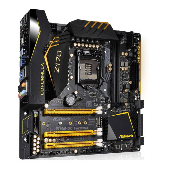
Page 13: Motherboard Layout
Z170M OC Formula 1.3 Motherboard Layout Power ATX12V1 CPU_FAN2 Reset USB 3.1 T: USB31_TA_1 MENU B: USB31_TC_1 USB 3.0 T: USB1 B: USB2 USB 3.0 Top: T: USB3 RJ-45 B: USB4 DRAM BOOT USB3_5_6 DIRKEY1 LN2MODE1 XMP_ON1 SLOWMODE1 CMOS CLRMOS1... - Page 14 No. Description ATX 12V Power Connector (ATX12V1) 2 x 288-pin DDR3 DIMM Slots (DDR3_A1, DDR3_B1) CPU Fan Connector (CPU_FAN2) V-Probe (VOL_CON1) Power Switch (PWR) Reset Switch (RST) Rapid OC Button (+) (PLUS) Rapid OC Button (–) (MINUS) Menu Button (MENU) ATX Power Connector (ATXPWR1) USB 3.0 Header (USB3_5_6) Post Status Checker (PSC)
- Page 15 Z170M OC Formula No. Description USB 2.0 Header (USB3_4) Power LED and Speaker Header (SPK_PLED1) Thunderbolt 3 AIC Connector (TB2) Thunderbolt 2/3 AIC Connector (TB1) Front Panel Audio Header (HD_AUDIO1) CPU Fan Connector (CPU_FAN1) Chassis Fan Connector (CHA_FAN3) Clear CMOS Jumper (CLRMOS1)
-
Page 16: I/O Panel
1.4 I/O Panel No. Description No. Description USB 2.0 Ports (USB12) USB 3.0 Ports (USB3_34) LAN RJ-45 Port* USB 3.0 Ports (USB3_12) Central / Bass (Orange) USB 3.1 Type-A Port (USB31_TA_1) Rear Speaker (Black) USB 3.1 Type-C Port (USB31_TC_1) Line In (Light Blue) DisplayPort 1.2 Front Speaker (Lime)** HDMI Port... - Page 17 Z170M OC Formula * There are two LEDs on each LAN port. Please refer to the table below for the LAN port LED indications. ACT/LINK LED SPEED LED LAN Port Activity / Link LED Speed LED Status Description Status Description...
-
Page 18: Chapter 2 Installation
Chapter 2 Installation This is a Micro ATX form factor motherboard. Before you install the motherboard, study the configuration of your chassis to ensure that the motherboard fits into it. Pre-installation Precautions Take note of the following precautions before you install motherboard components or change any motherboard settings. -
Page 19: Installing The Cpu
Z170M OC Formula 2.1 Installing the CPU 1. Before you insert the 1151-Pin CPU into the socket, please check if the PnP cap is on the socket, if the CPU surface is unclean, or if there are any bent pins in the socket. Do not force to insert the CPU into the socket if above situation is found. - Page 21 Z170M OC Formula Please save and replace the cover if the processor is removed. The cover must be placed if you wish to return the motherboard for after service.
-
Page 22: Installing The Cpu Fan And Heatsink
2.2 Installing the CPU Fan and Heatsink... -
Page 23: Installing Memory Modules (Dimm)
Z170M OC Formula 2.3 Installing Memory Modules (DIMM) This motherboard provides two 288-pin DDR4 (Double Data Rate 4) DIMM slots. It is not allowed to install a DDR, DDR2 or DDR3 memory module into a DDR4 slot; other- wise, this motherboard and DIMM may be damaged. -
Page 25: Expansion Slots (Pci Express Slots)
Z170M OC Formula 2.4 Expansion Slots (PCI Express Slots) There are 3 PCI Express slots on the motherboard. Before installing an expansion card, please make sure that the power supply is switched off or the power cord is unplugged. Please read the documentation of the expansion card and make necessary hardware settings for the card before you start the installation. -
Page 26: Jumpers Setup
2.5 Jumpers Setup The illustration shows how jumpers are setup. When the jumper cap is placed on the pins, the jumper is “Short”. If no jumper cap is placed on the pins, the jumper is “Open”. The illustration shows a 3-pin jumper whose pin1 and pin2 are “Short” when a jumper cap is placed on these 2 pins. -
Page 27: Onboard Headers And Connectors
Z170M OC Formula 2.6 Onboard Headers and Connectors Onboard headers and connectors are NOT jumpers. Do NOT place jumper caps over these headers and connectors. Placing jumper caps over the headers and connectors will cause permanent damage to the motherboard. - Page 28 Serial ATA3 Connectors These eight SATA3 (SATA3_0 connectors support SATA see p.7, No. 20) data cables for internal (SATA3_1: storage devices with up see p.7, No. 22) to 6.0 Gb/s data transfer (SATA3_2: rate. The SATA3_0, see p.7, No. 21) SATA3_1 are shared with (SATA3_3: the SATA_EXP0.
- Page 29 Z170M OC Formula USB 3.0 Header Besides four USB 3.0 Dummy IntA_PA_D+ IntA_PB_D+ IntA_PA_D- (19-pin USB3_5_6) ports on the I/O panel, IntA_PB_D- IntA_PA_SSTX+ (see p.7, No. 11) there is one header on this IntA_PB_SSTX+ IntA_PA_SSTX- IntA_PB_SSTX- motherboard. Each USB IntA_PA_SSRX+...
- Page 30 CPU Fan Connectors This motherboard FAN_VOLTAGE (4-pin CPU_FAN1) provides a 4-Pin CPU fan CPU_FAN_SPEED FAN_SPEED_CONTROL (see p.7, No. 38) (Quiet Fan) connector. If you plan to connect a (3-pin CPU_FAN2) 3-Pin CPU fan, please FAN_VOLTAGE (see p.7, No. 3) connect it to Pin 1-3. CPU_FAN_SPEED ATX Power Connector This motherboard pro-...
- Page 31 Z170M OC Formula Thunderbolt 3 AIC Please connect a Thunderbolt™ DUMMY I2C_DATA Connector add-in card (AIC) to this I2C_CLOCK (10-pin TBT2) connector via the GPIO cable. (see p.7, No. 35) *Please install the Thunderbolt™ AIC card to PCIE2 (default slot).
- Page 32 PIN6 VCORE: CPU CORE VOLTAGE PIN7...
-
Page 33: Smart Switches
Z170M OC Formula 2.7 Smart Switches The motherboard has eleven smart switches: Power Switch, Reset Switch, Clear CMOS Switch, Rapid OC Buttons, Menu Button, Slow Mode Switch, BIOS Selection Switch, LN2 Mode Switch, Direct Key Button and XMP Switch. Power Switch... - Page 34 Slow Mode Switch If Slow Mode is on, the (SLOWMODE1) processor runs at lowest fre- (see p.7, No. 15) quency. BIOS Selection BIOS Selection Switch allows Switch the system to boot from either (BIOS_SEL1) BIOS A or BIOS B. (see p.7, No. 29) This motherboard has two BIOS chips, a primary BIOS (BIOS_A) and a backup BIOS (BIOS_ B), which enhances the safety and stability of your system.
-
Page 35: Dr. Debug
Z170M OC Formula 2.8 Dr. Debug Dr. Debug is used to provide code information, which makes troubleshooting even easier. Please see the diagrams below for reading the Dr. Debug codes. Code Description Please check if the CPU is installed correctly and then clear CMOS. - Page 36 Problem related to USB devices. Please try removing all USB devices. Problem related to memory. Please re-install the CPU and memory then clear CMOS. If the problem still exists, please install only one memory module or try using other memory modules.
-
Page 37: Post Status Checker
Z170M OC Formula 2.9 Post Status Checker Post Status Checker (PSC) diagnoses the computer when users power on the machine. It emits a red light to indicate whether the CPU, memory, VGA or storage is dysfunctional. The lights go off if the four mentioned above are function-... -
Page 38: Sli Tm And Quad Sli Tm Operation Guide
2.10 SLI and Quad SLI Operation Guide ® This motherboard supports NVIDIA and Quad SLI (Scalable Link Interface) technology that allows you to install up to two identical PCI Express x16 graphics cards. Requirements ® 1. You should only use identical SLI -ready graphics cards that are NVIDIA certified. - Page 39 Z170M OC Formula Step 3 Align and insert the ASRock Flexible SLI Bridge Connector Cable to the goldfingers on each graphics card. Make sure the ASRock Flexible SLI Bridge Connector Cable is firmly in place. Multi-GPU SLI Video Link Card...
-
Page 40: Driver Installation And Setup
2.10.2 Driver Installation and Setup Install the graphics card drivers to your system. After that, you can enable the ® Multi-Graphics Processing Unit (GPU) in the NVIDIA nView system tray utility. Please follow the below procedures to enable the multi-GPU. For SLI and Quad SLI mode... -
Page 41: Crossfirex Tm And Quad Crossfirex
Z170M OC Formula 2.11 CrossFireX and Quad CrossFireX Operation Guide This motherboard supports CrossFireX and Quad CrossFireX allows you to install up to two identical PCI Express x16 graphics cards. 1. You should only use identical CrossFireX -ready graphics cards that are AMD certified. - Page 42 Step 3 Connect a VGA cable or a DVI cable to the monitor connector or the DVI connector of the graphics card that is inserted to PCIE1 slot.
-
Page 43: Driver Installation And Setup
Z170M OC Formula 2.11.2 Driver Installation and Setup Step 1 Power on your computer and boot into OS. Step 2 Remove the AMD drivers if you have any VGA drivers installed in your system. The Catalyst Uninstaller is an optional download. We recommend using this utility to un- install any previously installed Catalyst drivers prior to installation. -
Page 44: M.2_Ssd (Ngff) Module Installation Guide
2.12 M.2_SSD (NGFF) Module Installation Guide The M.2, also known as the Next Generation Form Factor (NGFF), is a small size and versatile card edge connector that aims to replace mPCIe and mSATA. The Ultra M.2 Sockets support M.2 PCI Express module up to Gen3 x4 (32 Gb/s). * M2_1, SATA3_0, SATA3_1 and SATA_EXP0 share lanes. - Page 45 Z170M OC Formula Step 3 Move the standoff based on the module type and length. The standoff is placed at the nut location D by default. Skip Step 3 and 4 and go straight to Step 5 if you are going to use the default nut.
- Page 46 SATA3 2280 TM8PS4256GMC105 Team 256GB SATA3 2242 TM4PS4256GMC105 Transcend 256GB SATA3 2242 TS256GMTS400 Transcend 512GB SATA3 2280 TS512GMTS800 Transcend 512GB SATA3 2260 TS512GMTS600 For the latest updates of M.2_SSD (NFGG) module support list, please visit our website for details: http://www.asrock.com...
-
Page 47: Chapter 3 Software And Utilities Operation
Z170M OC Formula Chapter 3 Software and Utilities Operation 3.1 Installing Drivers The Support CD that comes with the motherboard contains necessary drivers and useful utilities that enhance the motherboard’s features. Running The Support CD To begin using the support CD, insert the CD into your CD-ROM drive. The CD automatically displays the Main Menu if “AUTORUN”... -
Page 48: Formula Drive
3.2 Formula Drive Formula Drive is ASRock’s multi purpose software suite with a new interface, more new features and improved utilities. 3.2.1 Installing Formula Drive Formula Drive can be downloaded from ASRock Live Update & APP Shop. After the installation, you will find the icon “Formula Drive“ on your desktop. Double- click the “Formula Drive“... - Page 49 Z170M OC Formula OC Tweaker Configurations for overclocking the system. System Info View information about the system. *The System Browser tab may not appear for certain models.
- Page 50 FAN-Tastic Tuning Configure up to five different fan speeds using the graph. The fans will automatically shift to the next speed level when the assigned temperature is met. Tech Service Contact Tech Service if you have problems with your computer. Please leave your contact information along with details of the problem.
- Page 51 Z170M OC Formula Settings Configure ASRock Formula Drive. Click to select "Auto run at Windows Startup" if you want Formula Drive to be launched when you start up the Windows operating system.
-
Page 52: Asrock Live Update & App Shop
Double-click on your desktop to access ASRock Live Update & APP Shop utility. *You need to be connected to the Internet to download apps from the ASRock Live Update & APP Shop. 3.3.1 UI Overview Category Panel Hot News... -
Page 53: Apps
Z170M OC Formula 3.3.2 Apps When the "Apps" tab is selected, you will see all the available apps on screen for you to download. Installing an App Step 1 Find the app you want to install. The most recommended app appears on the left side of the screen. The other various apps are shown on the right. - Page 54 Step 3 If you want to install the app, click on the red icon to start downloading. Step 4 When installation completes, you can find the green "Installed" icon appears on the upper right corner. To uninstall it, simply click on the trash can icon *The trash icon may not appear for certain apps.
- Page 55 Z170M OC Formula Upgrading an App You can only upgrade the apps you have already installed. When there is an available new version for your app, you will find the mark of "New Version" appears below the installed app icon.
-
Page 56: Bios & Drivers
3.3.3 BIOS & Drivers Installing BIOS or Drivers When the "BIOS & Drivers" tab is selected, you will see a list of recommended or critical updates for the BIOS or drivers. Please update them all soon. Step 1 Please check the item information before update. Click on to see more details. -
Page 57: Setting
Z170M OC Formula 3.3.4 Setting In the "Setting" page, you can change the language, select the server location, and determine if you want to automatically run the ASRock Live Update & APP Shop on Windows startup. -
Page 58: Enabling Usb Ports For Windows® 7 Installation
Intel® USB 3.0 eXtensible Host Controller (xHCI) drivers packed into the ISO file. Requirements • A Windows® 7 installation disk or USB drive USB 3.0 drivers (included in the ASRock Support CD or website) • A Windows® PC • Win7 USB Patcher (included in the ASRock Support CD or website) •... - Page 59 Select the “Win7 Folder” from Step1 by clicking the red circle as shown as the picture below. Step 4 Select the “USB Driver Folder” by clicking the red circle as shown as the picture below. If you are using ASRock’s Support CD for the USB 3.0 driver, please select your CD-ROM.
- Page 60 Step 5 Select where to save the ISO file by pressing the red circle as shown as the picture below. Step 6 If you want to burn the patched image to a CD, please check “Burn Image” and select “Target Device to Burn”.
-
Page 61: Chapter 4 Uefi Setup Utility
Z170M OC Formula Chapter 4 UEFI SETUP UTILITY 4.1 Introduction This section explains how to use the UEFI SETUP UTILITY to configure your system. You may run the UEFI SETUP UTILITY by pressing <F2> or <Del> right after you power on the computer, otherwise, the Power-On-Self-Test (POST) will continue with its test routines. -
Page 62: Ez Mode
4.2 EZ Mode The EZ Mode screen appears when you enter the BIOS setup program by default. EZ mode is a dashboard which contains multiple readings of the system’s current status. You can check the most crucial information of your system, such as CPU speed, DRAM frequency, SATA information, fan speed, etc. -
Page 63: Advanced Mode
Z170M OC Formula 4.3 Advanced Mode The Advanced Mode provides more options to configure the BIOS settings. Refer to the following sections for the detailed configurations. To access the EZ Mode, press <F6> or click the "EZ Mode" button at the upper right corner of the screen. -
Page 64: Navigation Keys
4.3.2 Navigation Keys Use < > key or < > key to choose among the selections on the menu bar, and use < > key or < > key to move the cursor up or down to select items, then press <Enter>... -
Page 65: Main Screen
Z170M OC Formula 4.4 Main Screen When you enter the UEFI SETUP UTILITY, the Main screen will appear and display the system overview. Favorite Display your collection of BIOS items. Press F5 to add/remove your favorite items. -
Page 66: Oc Tweaker Screen
4.5 OC Tweaker Screen In the OC Tweaker screen, you can set up overclocking features. Because the UEFI software is constantly being updated, the following UEFI setup screens and descriptions are for reference purpose only, and they may not exactly match what you see on your screen. - Page 67 Z170M OC Formula Load Optimized CPU OC Setting You can use this option to load optimized CPU overclocking setting. Please note that overclocking may cause damage to your CPU and motherboard. It should be done at your own risk and expense.
- Page 68 Stable Delay Configure the delay time after BCLK setting for stable signal. CPU Amplitude Configure the CPU Amplitude. CPU Slew Rate Configure the CPU Slew Rate. CPU PLL ORT Configure the CPU PLL ORT. Divider Configure the BCLK divider. Boot Performance Mode Select the performance state that the BIOS will set before OS handoff.
- Page 69 Z170M OC Formula Long Duration Maintained Configure the period of time until the CPU ratio is lowered when the Long Duration Power Limit is exceeded. Short Duration Power Limit Configure Package Power Limit 2 in watts. When the limit is exceeded, the CPU ratio will be lowered immediately.
- Page 70 BCLK Frequency The CPU speed is determined by the CPU Ratio multiplied with the BCLK. Increasing the BCLK will increase the internal CPU clock speed but also affect the clock speed of other components. DRAM Reference Clock Select Auto for optimized settings. DRAM Frequency If [Auto] is selected, the motherboard will detect the memory module(s) inserted and assign the appropriate frequency automatically.
- Page 71 Z170M OC Formula RAS to RAS Delay (tRRD_L) The number of clocks between two rows activated in different banks of the same rank. RAS to RAS Delay (tRRD_S) The number of clocks between two rows activated in different banks of the same rank.
- Page 72 tRDRD_dr Configure between module read to read delay. tRDRD_dd Configure between module read to read delay. tRDWR_sg Configure between module read to write delay. tRDWR_dg Configure between module read to write delay. tRDWR_dr Configure between module read to write delay. tRDWR_dd Configure between module read to write delay.
- Page 73 Z170M OC Formula tWRWR_dd Configure between module write to write delay. RTL Init Value Configure round trip latency init value for round trip latency training. IO-L Init Value Configure IO latency init value for IO latency training. RTL (CH A) Configure round trip latency for channel A.
- Page 74 tAONPD Configure tAONPD. Configure tXP. tXPDLL Configure tXPDLL. tPRPDEN Configure tPRPDEN. tRDPDEN Configure tRDPDEN. tWRPDEH Configure tWRPDEH. OREF_RI Configure OREF_RI. tREFIx9 Configure tREFIx9. tXSDLL Configure tXSDLL. txs_offset Configure txs_offset. tZQOPER Configure tZQOPER. tMOD Configure tMOD. ZQCS_period Configure ZQCS_period.
- Page 75 Z170M OC Formula tZQCS Configure tZQCS. Advanced Setting ODT WR (CH A) Configure the memory on die termination resistors' WR for channel A. ODT WR (CH B) Configure the memory on die termination resistors' WR for channel B. ODT PARK (CH A) Configure the memory on die termination resistors' PARK for channel A.
- Page 76 Voltage Configuration CPU Vcore Voltage Configure the voltage for the CPU Vcore. CPU Load-Line Calibration CPU Load-Line Calibration helps prevent CPU voltage droop when the system is under heavy load. CPU Vcore Pwm Switching Frequency Configure the PWM Switching Frequency for CPU Vcore. CPU Vcore Voltage Turn on All Phase Enable the CPU Vcore Voltage Turn On All Phase or set it to [Auto].
- Page 77 Z170M OC Formula Eventual DRAM Voltage Configure the DRAM voltage level used for booting into OS. DRAM Activating Power Supply Configure the voltage for the DRAM Activating Power Supply. VTT DDR Voltage Configure the VTT DDR voltage. PCH +1.0 Voltage Configure the chipset voltage (1.0V).
- Page 78 Load User Default Load previously saved user defaults.
-
Page 79: Advanced Screen
Z170M OC Formula 4.6 Advanced Screen In this section, you may set the configurations for the following items: CPU Configuration, Chipset Configuration, Storage Configuration, Intel® Thunderbolt, Super IO Configuration, ACPI Configuration, USB Configuration and Trusted Computing. Setting wrong values in this section may cause the system to malfunction. -
Page 80: Cpu Configuration
4.6.1 CPU Configuration Microcode Update Select the CPU microcode update revision. Intel Hyper Threading Technology Intel Hyper Threading Technology allows multiple threads to run on each core, so that the overall performance on threaded software is improved. Active Processor Cores Select the number of cores to enable in each processor package. - Page 81 Z170M OC Formula CPU C7 State Support Enable C7 deep sleep state for lower power consumption Package C State Support Enable CPU, PCIe, Memory, Graphics C State Support for power saving. CPU Hardware P States Support Enable CPU Hardware P States Support for additional benefits in the energy efficiency.
-
Page 82: Chipset Configuration
4.6.2 Chipset Configuration Primary Graphics Adapter Select a primary VGA. Top of Lower Usable DRAM Set the maximum value of TOLUD. Set this item to Dynamic to allow TOLUD to adjust automatically based on the largest MMIO length of the installed graphic controller. - Page 83 Z170M OC Formula PCH PCIE ASPM Support This option enables/disables the ASPM support for all PCH PCIE devices. DMI ASPM Support This option enables/disables the control of ASPM on CPU side of the DMI Link. PCH DMI ASPM Support This option enables/disables the ASPM support for all PCH DMI devices.
- Page 84 Good Night LED By enabling Good Night LED, the Power/HDD LEDs will be switched off when the system is on. It will also automatically switch off the Power and Keyboard LEDs when the system enters into Standby/Hibernation mode. Onboard Debug Port LED Enable/disable the onboard Dr.
-
Page 85: Storage Configuration
Z170M OC Formula 4.6.3 Storage Configuration SATA Controller(s) Enable/disable the SATA controllers. SATA Mode Selection AHCI: Supports new features that improve performance. RAID: Combine multiple disk drives into a logical unit. AHCI (Advanced Host Controller Interface) supports NCQ and other new features that will improve SATA disk performance but IDE mode does not have these advantages. - Page 86 ASMedia SATA3 Mode IDE: For better compatibility. AHCI: Supports new features that improve performance.
-
Page 87: Intel® Thunderbolt
Z170M OC Formula 4.6.4 Intel® Thunderbolt™ 2 Intel(R) Thunderbolt Technonogy Enable/Disable the Intel(R) Thunderbolt function. -
Page 88: Super Io Configuration
4.6.5 Super IO Configuration Serial Port Enable or disable the Serial port. Serial Port Address Select the address of the Serial port. PS2 Y-Cable Enable the PS2 Y-Cable or set this option to Auto. -
Page 89: Acpi Configuration
Z170M OC Formula 4.6.6 ACPI Configuration Suspend to RAM Select disable for ACPI suspend type S1. It is recommended to select auto for ACPI S3 power saving. ACPI HEPT Table Enable the High Precision Event Timer for better performance. PS/2 Keyboard Power On Allow the system to be waked up by a PS/2 Keyboard. - Page 90 USB Keyboard/Remote Power On Allow the system to be waked up by an USB keyboard or remote controller. USB Mouse Power On Allow the system to be waked up by an USB mouse.
-
Page 91: Usb Configuration
Z170M OC Formula 4.6.7 USB Configuration Legacy USB Support Enable or disable Legacy OS Support for USB 2.0 devices. If you encounter USB compatibility issues it is recommended to disable legacy USB support. Select UEFI Setup Only to support USB devices under the UEFI setup and Windows/Linux operating systems only. -
Page 92: Trusted Computing
4.6.8 Trusted Computing Security Device Support Enable or disable BIOS support for security device. -
Page 93: Tools
In order to prevent users from bypassing OMG, guest accounts without permission to modify the system time are required. UEFI Tech Service Contact ASRock Tech Service if you are having trouble with your PC. Please setup network configuration before using UEFI Tech Service. Easy RAID Installer Easy RAID Installer helps you to copy the RAID driver from the support CD to your USB storage device. - Page 94 Easy Driver Installer For users that don’t have an optical disk drive to install the drivers from our support CD, Easy Driver Installer is a handy tool in the UEFI that installs the LAN driver to your system via an USB storage device, then downloads and installs the other required drivers automatically.
- Page 95 Intel MEI Recovery Configure Intel ME (Management Engine) recovery. Internet Flash - DHCP (Auto IP), Auto ASRock Internet Flash downloads and updates the latest UEFI firmware version from our servers for you. Please setup network configuration before using Internet Flash.
-
Page 96: Hardware Health Event Monitoring Screen
4.8 Hardware Health Event Monitoring Screen This section allows you to monitor the status of the hardware on your system, including the parameters of the CPU temperature, motherboard temperature, fan speed and voltage. Fan-Tastic Tuning Select a fan mode for CPU Fans 1&2, or choose Customize to set 5 CPU temperatures and assign a respective fan speed for each temperature. - Page 97 Z170M OC Formula Chassis Fan 2 Setting Select a fan mode for Chassis Fan 2, or choose Customize to set 5 CPU temperatures and assign a respective fan speed for each temperature. Chassis Fan 2 Temp Source Select a fan temperature source for Chassis Fan 2.
-
Page 98: Security Screen
4.9 Security Screen In this section you may set or change the supervisor/user password for the system. You may also clear the user password. Supervisor Password Set or change the password for the administrator account. Only the administrator has authority to change the settings in the UEFI Setup Utility. Leave it blank and press enter to remove the password. -
Page 99: Boot Screen
Z170M OC Formula 4.10 Boot Screen This section displays the available devices on your system for you to configure the boot settings and the boot priority. Fast Boot Fast Boot minimizes your computer's boot time. In fast mode you may not boot from an USB storage device. - Page 100 Full Screen Logo Enable to display the boot logo or disable to show normal POST messages. AddOn ROM Display Enable AddOn ROM Display to see the AddOn ROM messages or configure the AddOn ROM if you've enabled Full Screen Logo. Disable for faster boot speed. Boot Failure Guard Message If the computer fails to boot for a number of times the system automatically restores the default settings.
- Page 101 Z170M OC Formula CSM (Compatibility Support Module) Enable to launch the Compatibility Support Module. Please do not disable unless you’re running a WHCK test. If you are using Windows 8.1 64-bit and all of your devices support UEFI, you may also disable CSM for faster boot speed.
-
Page 102: Exit Screen
4.11 Exit Screen Save Changes and Exit When you select this option the following message, “Save configuration changes and exit setup?” will pop out. Select [OK] to save changes and exit the UEFI SETUP UTILITY. Discard Changes and Exit When you select this option the following message, “Discard changes and exit setup?”... - Page 103 Contact Information If you need to contact ASRock or want to know more about ASRock, you’re welcome to visit ASRock’s website at http://www.asrock.com; or you may contact your dealer for further information. For technical questions, please submit a support request form at http://www.asrock.com/support/tsd.asp...