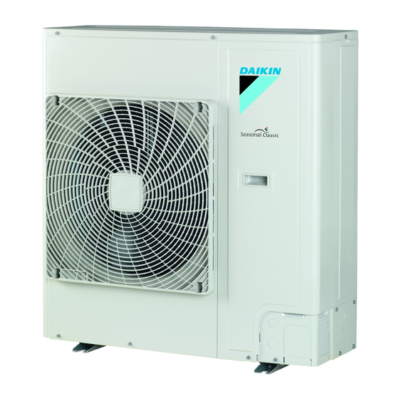
Daikin RZQG100L9V1B Installation Manual
Split system air conditioners
Hide thumbs
Also See for RZQG100L9V1B:
- Installer's reference manual (32 pages) ,
- Service manual (215 pages)
Table of Contents
Advertisement
Advertisement
Table of Contents

Summary of Contents for Daikin RZQG100L9V1B
- Page 1 Installation manual Split system air conditioners RZQG71L9V1B RZQG100L9V1B RZQG125L9V1B RZQG140L9V1B RZQG71L8Y1B RZQG100L8Y1B RZQG125L8Y1B RZQG140L7Y1B RZQSG100L9V1B RZQSG125L9V1B RZQSG140L9V1B RZQSG100L8Y1B Installation manual RZQSG125L8Y1B English Split system air conditioners RZQSG140L7Y1B...
- Page 2 (mm) — ≥100 A, B, C — ≥100 ≥100 ≥100 B, E — ≥100 ≥1000 ≤500 A, B, C, E — ≥150 ≥150 ≥150 ≥1000 ≤500 — ≥500 D, E — ≥1000 ≤500 ≥500 — B, D ≥100 ≥500 B, D, E <H ≤½H ≥250...
- Page 3 2P308775-6E...
-
Page 4: Table Of Contents
▪ A subset of the latest technical data is available on the regional Checking the refrigerant piping ..........Daikin website (publicly accessible). 4.3.1 Checking refrigerant piping: Setup......▪ The full set of latest technical data is available on the Daikin 4.3.2 To check for leaks............Business Portal (authentication required). 4.3.3 To perform vacuum drying .......... -
Page 5: Preparation
3 Preparation NOTICE Preparation Fix the outdoor unit to the foundation bolts using nuts with resin washers (a). If the coating on the fastening area is Preparing the installation site stripped off, the metal can rust easily. 3.1.1 Installation site requirements of the outdoor unit 4.1.2 To install the outdoor unit... -
Page 6: To Prevent The Outdoor Unit From Falling Over
4 Installation 1 Remove the knockout hole (a) by tapping on the attachment INFORMATION points with a flat head screwdriver and a hammer. 2 Remove the burrs, and paint the edges and areas around the edges using repair paint to prevent rusting. ▪... -
Page 7: To Determine If Oil Traps Are Required
4 Installation Checking the refrigerant piping 4.3.1 Checking refrigerant piping: Setup WARNING Provide adequate measures to prevent that the unit can be used as a shelter by small animals. Small animals that R410A make contact with electrical parts can cause malfunctions, smoke or fire. -
Page 8: Charging Refrigerant
4 Installation 4.4.2 To determine the additional refrigerant If the pressure… Then… amount Does not change There is no moisture in the system. This procedure is To determine if adding additional refrigerant is necessary finished. Then Increases There is moisture in the system. -
Page 9: To Determine The Complete Recharge Amount
4 Installation Examples 4.4.4 Charging refrigerant: Setup Layout Additional refrigerant amount (R) "4.3.1 Checking refrigerant piping: Setup" on page 7. L2=7 m Case: Twin, standard liquid pipe size (Ø6.4 mm) 1 G1 Total Ø9.5 => G1=35 m 4.4.5 To charge additional refrigerant L3=5 m (Ø6.4 mm) G2 Total Ø6.4 =>... -
Page 10: Connecting The Electrical Wiring
4 Installation ▪ EN/IEC 61000‑3‑12 provided that the short-circuit power S CAUTION greater than or equal to the minimum S value at the interface For use of units in applications with temperature alarm point between the user's supply and the public system. settings it is recommended to foresee a delay of 10 ▪... -
Page 11: Finishing The Outdoor Unit Installation
4 Installation Connecting to the When cables are routed from the unit, a frame protection sleeve for the conduits (PG insertions) can be inserted at the knockout hole. When you do not use a wire conduit, protect the wires with vinyl tubes to prevent the edge of the knockout hole from cutting the wires. -
Page 12: To Check The Insulation Resistance Of The Compressor
5 Commissioning 4.6.2 To check the insulation resistance of the There are NO damaged components or squeezed pipes on the inside of the indoor and outdoor units. compressor There are NO refrigerant leaks. NOTICE The correct pipe size is installed and the pipes are If, after installation, refrigerant accumulates in the compressor, the insulation resistance over the poles can properly insulated. -
Page 13: Error Codes When Performing A Test Run
6 Disposal 3 Check operation for 3 minutes. Error code Possible cause 4 Check operation of the airflow direction. ▪ There is a voltage imbalance. Action Result ▪ There is a missing phase in case of three-phase power supply units. Note: Press. -
Page 14: Technical Data
7 Technical data Technical data A subset of the latest technical data is available on the regional Daikin website (publicly accessible). The full set of latest technical data is available on the Daikin Business Portal (authentication required). Service space: Outdoor unit Suction side In the illustrations below, the service space at the suction side is based on 35°C DB and cooling operation. -
Page 15: Wiring Diagram: Outdoor Unit
7 Technical data Wiring diagram: Outdoor unit ▪ K2R (A1P): Magnetic relay (E1H option) (RZQ(S)G_Y1) The wiring diagram is delivered with the unit, located at the inside of ▪ K2R (A2P): Magnetic relay the service cover. K10R, K13R~K15R Magnetic relay Notes for RZQ(S)G_V1: Magnetic relay E1H (option) Symbols (see legend). - Page 16 7 Technical data Colours: Black Blue Brown Green Orange White Yellow Installation manual RZQG71~140L_V1+Y1 + RZQSG100~140L_V1+Y1 Split system air conditioners 4P385521-1C – 2019.04...
- Page 20 4P385521-1 C 0000000$ 4P385521-1 B 0000000 4P385521-1C 2019.04...


