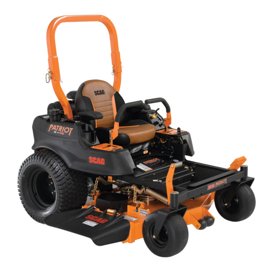
Scag Power Equipment Patriot SPZ52H-22FX Operator's Manual
Hide thumbs
Also See for Patriot SPZ52H-22FX:
- Operator's manual (74 pages) ,
- Operator's manual (76 pages)
Table of Contents
Advertisement
Congratulations on owning a Scag mower! This manual contains the operating
instructions and safety information for your Scag mower. Reading this manual
can provide you with assistance in maintenance and adjustment procedures to
keep your mower performing to maximum efficiency. The specific models that
this book covers are listed on the inside cover. Before operating your machine,
please read all the information enclosed.
© 2020
Scag Power Equipment
Division of Metalcraft of Mayville, Inc.
OPERATOR'S
MANUAL
Models:
SPZ52H-22FX
SPZ52H-23CV
SPZ61H-23FX
SPZ61H-25CV
PART NO. 03470
PRINTED 09/2020
PRINTED IN USA
Advertisement
Table of Contents

Related Manuals for Scag Power Equipment Patriot SPZ52H-22FX


Summary of Contents for Scag Power Equipment Patriot SPZ52H-22FX
- Page 1 The specific models that this book covers are listed on the inside cover. Before operating your machine, please read all the information enclosed. © 2020 PART NO. 03470 Scag Power Equipment PRINTED 09/2020 Division of Metalcraft of Mayville, Inc. PRINTED IN USA...
- Page 2 WARNING FAILURE TO FOLLOW SAFE OPERATING PRACTICES MAY RESULT IN SERIOUS INJURY OR DEATH. • Read this manual completely as well as other manuals that came with your mower. • DO NOT operate on steep slopes. To check a slope, attempt to back up it (with the cutter deck down).
-
Page 3: Table Of Contents
Table of Contents Table of Contents SECTION 1 - GENERAL INFORMATION ...................1 1.1 INTRODUCTION ............................1 1.2 DIRECTION REFERENCE ...........................1 1.3 SERVICING THE ENGINE AND DRIVE TRAIN COMPONENTS ..............1 1.4 SYMBOLS ..............................2 SECTION 2 - SAFETY INFORMATION ..................3 2.1 INTRODUCTION ............................3 2.2 SIGNAL WORDS ............................3 2.3 BEFORE OPERATION CONSIDERATIONS ....................3 2.4 TESTING THE SAFETY INTERLOCK SYSTEM ..................4... - Page 4 Table of Contents SECTION 5 - TROUBLESHOOTING CUTTING CONDITIONS ..........21 SECTION 6 - ADJUSTMENTS ....................24 6.1 PARKING BRAKE ADJUSTMENT ......................24 6.2 TRAVEL ADJUSTMENTS ..........................25 6.3 THROTTLE CONTROL AND CHOKE ADJUSTMENTS ................26 6.4 BELT ADJUSTMENT ..........................26 6.5 BELT ALIGNMENT .............................26 6.6 CUTTER DECK ADJUSTMENTS ......................27 6.7 ELECTRIC CLUTCH ADJUSTMENT ......................29 SECTION 7 - MAINTENANCE ....................30 7.1 MAINTENANCE CHART - RECOMMENDED SERVICE INTERVALS ............30...
-
Page 5: Section 1 - General Information
Attachments and accessories manufactured by companies industry. However, the prolonged life and maximum other than Scag Power Equipment are not approved for use efficiency of your mower depends on you following the on this machine. See Section 8, Paragraph 8-1. -
Page 6: Symbols
Section 1 1.4 SYMBOLS SYMBOL DESCRIPTION SYMBOL DESCRIPTION Choke Transmission Parking Brake Spinning Blade 48071S On/Start Spring Tension on Idler Off/Stop Falling Hazard Thrown Object Hazard Fast Slow Continuously Variable - Linear Cutting Element - Basic Symbol Pinch Point Cutting Element - Engage 481039S Hour meter/Elapsed Operating Hours Cutting Element - Disengage... -
Page 7: Section 2 - Safety Information
Section 2 SAFETY INFORMATION 2.1 INTRODUCTION DANGER Your mower is only as safe as the operator. Carelessness or operator error may result in serious bodily injury The signal word “DANGER” denotes that an extremely or death. Hazard control and accident prevention are hazardous situation exists on or near the machine that dependent upon the awareness, concern, prudence, and could result in high probability of death or irreparable injury... -
Page 8: Testing The Safety Interlock System
If the safety interlock system does not operate as described below, contact your local machine over prolonged periods of time can Authorized Scag Power Equipment Dealer immediately to cause loss of hearing. have the safety interlock system repaired. -
Page 9: Operation Considerations
Section 2 2. Sit in the seat in the operating position, engage the 2. Reduce speed and exercise extreme caution on parking brake, move the PTO switch to the OFF slopes and sharp turns to prevent tipping or loss (down) position, move either of the steering control of control. -
Page 10: Roll-Over Protection System
Section 2 12. Disengage power to cutter deck before crossing 22. Tie the mower down securely using straps, chains, roads, walks or gravel drives. cable, or ropes. Both front and rear straps must be directed down and outward from machine. 13. - Page 11 Section 2 Lower the roll bar only when absolutely necessary. It is recommended that the seat belt be inspected on a daily basis for signs of damage. Any seat belt system that 1. To lower the roll bar, remove the hairpin cotter pins shows cuts, fraying, extreme or unusual wear, significant and remove the two (2) lock pins.
-
Page 12: Maintenance Considerations & Storage
Section 2 2. Disengage drives, lower implement, set parking WARNING brake, stop engine and remove key or disconnect spark plug wire to prevent accidental starting of the engine when servicing or adjusting the machine. Reduce speed when turning, operating on slopes, Wait for all movement to stop before adjusting, slick or wet surfaces. -
Page 13: Using A Spark Arrestor
Section 2 WARNING Hydraulic fluid is under high pressure and can penetrate skin causing injury. If hydraulic fluid is injected into the skin, it must be surgically removed within a few hours by a doctor or gangrene may result. Keep body and hands away from pinholes or nozzles that eject hydraulic fluid under high pressure.Use paper or cardboard and not hands to search for leaks. -
Page 14: Safety And Instructional Decals
Section 2 2.10 SAFETY AND INSTRUCTIONAL DECALS 483405 483633 483402 483505 WARNING WARNING Operation of this equipment may create sparks that can start res around dry vegetation. A spark 481568 arrestor may be required. The operator should contact local re agencies for laws or regulations relating to re prevention requirements. -
Page 15: Section 3 - Specifications
Section 3 SPECIFICATIONS 3.1 ENGINE General Type ....................Heavy Duty Industrial/Commercial Gasoline Model: Scag Model SPZ52H-22FX ......................Kawasaki FX691V Scag Model SPZ61H-23FX ......................Kawasaki FX730V Scag Model SPZ52H-23CV ........................Kohler CV732 Scag Model SPZ61H-25CV ........................Kohler CV742 Displacement: Kawasaki 22FX (FX691V) ..........................726cc Kawasaki 23FX (FX730V) ..........................726cc Kohler 23CV ............................... -
Page 16: Cutter Deck
Section 3 Tire Pressure: Front Caster............................... 25 PSI Drive ..................................8 PSI Fuel Tank ........Single 6-1/2 Gallon Seamless Roto-Low Perm Tank with Large Opening and Fuel Cap Seat ......................Padded, Thick Cushion with Suspension Seat Travel Speed: 52" Forward ............................0 up to 8.5 MPH 61"... -
Page 17: Section 4 - Operating Instructions
Section 4 OPERATING INSTRUCTIONS 1. Ignition Switch (Figure 4-1). The ignition switch WARNING is used to start the engine and has three positions; OFF, ON, and START. 2. Mower Deck Switch (Figure 4-1). Used to engage Do not attempt to operate this mower unless you and disengage the mower drive system. - Page 18 Section 4 6. Hourmeter (Figure 4-1). Indicates the number of hours the engine has been operated. It operates whenever the engine is running. Has preset maintenance reminders for engine and hydraulic system oil changes. Will start flashing scheduled maintenance 2 hours before preset time and continue flashing until 2 hours after.
-
Page 19: Safety Interlock System
Section 4 13. Deck Lift Foot Lever (Figure 4-1). Used to raise -NOTE- and lower the cutter deck. 3. All SPZ models will start with the parking brake 14. Cutting Height Adjustment (Figure 4-1). Used to engaged or disengaged. For all test procedures set the cutter deck at the desired cutting height. -
Page 20: Starting The Engine
Section 4 4.5 STARTING THE ENGINE Practice operating the mower until you are comfortable with the controls before proceeding to mow. CAUTION FORWARD TRAVEL DO NOT USE STARTING FLUIDS. Use of starting To travel forward with the mower, fully depress the brake fluids in the air intake system may be potentially pedal forward to disengage the parking brake lock latch and explosive or cause a “runaway”... -
Page 21: Engaging The Deck Drive (Cutter Blades)
Section 4 4.7 ENGAGING THE DECK DRIVE (CUTTER REVERSE TRAVEL BLADES) CAUTION 1. Set the throttle at about 3/4 speed. Do not attempt to engage the deck drive at high speed as this shortens the electric clutch life — use only moderate engine speed when engaging the deck drive. -
Page 22: Hillside Operation
Section 4 4.8 HILLSIDE OPERATION 2. Place the steering control levers in the neutral position. 3. Disengage the cutter blades. WARNING 4. Slow the engine to idle speed. 5. Fully depress the brake pedal and pull the parking DO NOT operate on steep slopes. To check a slope, brake lever back to engage the parking brake. -
Page 23: Removing Clogged Material
Section 4 2. The discharge chute must not be removed and 4.11 REMOVING CLOGGED MATERIAL must be kept in the lowest position to deflect grass clippings and thrown objects downward. Direct the side discharge away from sidewalks or streets to minimize DANGER cleanup of clippings. -
Page 24: Towing (Optional Hitch Accessory)
Section 4 CUTTER DECK CUTTING HEIGHT RELEASE LEVER ADJUSTMENT DECK LIFT Figure 4-6. Adjusting Cutting Height 2015 SPZ CDHA 3. Insert the pin into the cutting height index at the desired cutting height. Push forward on the deck lift foot lever, hold in place and lift up on the deck release lever. -
Page 25: Section 5 - Troubleshooting Cutting Conditions
Section 5 TROUBLESHOOTING CUTTING CONDITIONS CONDITION CAUSE CURE STRINGERS - OCCASIONAL Low engine RPM Run engine at full RPM BLADES OF UNCUT GRASS Ground speed too fast Slow speed to adjust for conditions Wet grass Cut grass after it has dried out Dull blades, incorrect sharpening Sharpen blades Deck plugged, grass accumulation... - Page 26 Section 5 TROUBLESHOOTING CUTTING CONDITIONS (CONT'D) CONDITION CAUSE CURE U N E V E N C U T O N F L AT Lift worn from blade Replace blade GROUND - WAVY HIGH-LOW APPEARANCE, SCALLOPED Blade upside down Mount with cutting edge toward ground CUT, OR ROUGH CONTOUR Deck plugged, grass accumulation Clean underside of deck...
- Page 27 Section 5 TROUBLESHOOTING CUTTING CONDITIONS (CONT'D) CONDITION CAUSE CURE SCALPING - BLADES HITTING Low tire pressures Check and adjust pressures DIRT OR CUTTING VERY CLOSE TO THE GROUND Ground speed too fast Slow speed to adjust for conditions May need to reduce ground speed, raise Cutting too low cutting height, change direction of cut, and/or change pitch and level...
-
Page 28: Section 6 - Adjustments
Section 6 ADJUSTMENTS 6.1 PARKING BRAKE ADJUSTMENT WARNING PULL BACK ON Do not operate the mower if the parking brake PARKING BRAKE is not operable. Possible severe injury could LATCH result. PUSH BRAKE PEDAL FORWARD The parking brake linkage should be adjusted whenever the parking brake lock latch is placed in the “ENGAGE”... -
Page 29: Travel Adjustments
Section 6 6.2 TRAVEL ADJUSTMENTS 3. Run the engine at full operating speed and check if the machine creeps forward or backwards. Neutral or tracking adjustments will need to be made if: 4. Adjust the RH wheel by loosening the jam nuts on the steering control rod and turning the adjustment nut until the drive wheel turns in the forward A. -
Page 30: Throttle Control And Choke Adjustments
These adjustments must be performed by your Authorized before beginning work. Scag Power Equipment Dealer to ensure proper and efficient running of the engine. Should either need adjustment, contact your authorized Scag service center. -
Page 31: Cutter Deck Adjustments
Section 6 6.6 CUTTER DECK ADJUSTMENTS CUTTER DECK PITCH The pitch of the cutter deck should be equal between Cutter deck level, pitch and height are set at the factory. the front and rear of the cutter deck for proper cutting However, if these adjustments should ever need to be performance. - Page 32 Section 6 LOOSEN HERE LOOSEN HERE ADJUST HERE ADJUST HERE 2015 SPZ DLA 2015 SPZ RSDA Figure 6-6. Cutter Deck Pitch Adjustment - NOTE - To prevent the cutter deck from teetering, all four (4) cutter deck hanging chains must have tension on them.
-
Page 33: Electric Clutch Adjustment
Section 6 6.7 ELECTRIC CLUTCH ADJUSTMENT ADJUSTMENT NUTS The electric clutch serves two functions in the operation of the mower. In addition to starting and stopping the power flow to the cutter blades, the clutch also acts as a brake to assist in stopping blade rotation when the PTO is switched off or the operator presence circuit is interrupted. -
Page 34: Section 7 - Maintenance
Section 7 MAINTENANCE 7.1 MAINTENANCE CHART - RECOMMENDED SERVICE INTERVALS HOURS PROCEDURE COMMENTS BREAK-IN (FIRST 10) Check all hardware for tightness Check hydraulic oil level See paragraph 7.2 Check all belts for proper alignment See paragraph 7.7 Check engine oil level See paragraph 7.3 Check hydraulic hoses for leaks U s e ex t r e m e c a u t i o n w h e n... -
Page 35: Hydraulic System
Section 7 7.2 HYDRAULIC SYSTEM 4. Remove the hydraulic filters from both axles and allow the fluid to drain into the container. Properly discard the oil when the system has drained A. CHANGING HYDRAULIC OIL completely. See Figure 7-2. 5. Once the hydraulic system has drained, install new The hydraulic system oil and filter should be changed after the first 75-100 hours of machine operation and every 400 hydraulic oil filters to both axles by hand, turn 3/4... -
Page 36: Engine Oil
Section 7 12. While in the operator's position, start the engine and FILL PORT PLUG disengage the parking brake. 13. Run the engine at 1/2 throttle and move the steering control levers to full forward and reverse 5 to 6 times. 14. -
Page 37: Engine Fuel System
Section 7 ENGINE OIL FILL FILLER NECK INSERT & DIPSTICK FUEL LEVEL ENGINE OIL FILTER Figure 7-6. C.A.R.B. / EPA Phase 3 Fuel Level To avoid personal injury or property damage, use extreme care in handling gasoline. Gasoline is extremely flammable and the vapors are explosive. -
Page 38: Engine Air Cleaner
Section 7 A. CLEANING AND/OR REPLACING AIR 8. If fuel is spilled on clothing, change clothing immediately and wash affected skin. CLEANER ELEMENT 9. Replace gas cap and tighten securely. For Low For any air cleaner, the operating environment dictates Emission (LE) and EPA Phase 3 (produced after the air cleaner service periods. -
Page 39: Drive Belts
Section 7 WARNING WARNING BATTERIES PRODUCE EXPLOSIVE GASES. Electric storage battery fluid contains sulfuric Charge the battery in a well ventilated space so acid which is POISON and can cause SEVERE gases produced while charging can dissipate. CHEMICAL BURNS. Avoid contact of fluid with eyes, skin, or clothing. -
Page 40: Cutter Blades
Section 7 B. BLADE SHARPENING WARNING - NOTE - If the pump drive belt fails, steering control will be If possible, use a file to sharpen the blade. Using lost which could result in serious injury or death. a wheel grinder may burn the blade. Replace the pump drive belt as needed or every 400 hours / 2 years, whichever occurs first. -
Page 41: Tires
Section 7 7.10 BODY, DECK, AND UPHOLSTERY CAUTION CAUTION Inspect the cutter blade spacer(s) and washer for wear and/or cupping. Replace the worn parts. Worn spacer(s) and/or washer will not allow Do not wash any portion of the equipment while it proper tightening of the cutter blade and can lead is hot. -
Page 42: Section 8 - Illustrated Parts List
Section 8 ILLUSTRATED PARTS LIST 8.1 SCAG APPROVED ATTACHMENTS AND ACCESSORIES. Attachments and accessories manufactured by companies other than Scag Power Equipment are not approved for use on this machine. Scag approved attachments and accessories: • GC-SZL/SFZ/SPZ (p/n 901K, requires p/n 901H or 901J Install Kit) •... -
Page 43: Notes
Section 8 NOTES... -
Page 44: Cutter Deck
Section 8 52H CUTTER DECK 2018 SPZ52 CD... - Page 45 Section 8 52H CUTTER DECK Part No. Description Part No. Description 483304 Debris Shield 424528 Belt Cover 483303 Bearing 04063-01 Key, 1/4 x 1/4 x 1-1/4" 43693 Spacer 04112-06 Nut, 3/4-16 Spiral Lock 462014 Spindle Housing Assembly 483324 Pulley, 5.73" OD - 25mm Bore (Incl.
-
Page 46: Cutter Deck
Section 8 61H CUTTER DECK 2018 SPZ61 CD... - Page 47 Section 8 61H CUTTER DECK Part No. Description Part No. Description 483304 Debris Shield 425260 Belt Cover 483303 Bearing 04063-01 Key, 1/4 x 1/4 x 1-1/4" 43693 Spacer 04112-06 Nut, 3/4-16 Spiral Lock 462014 Spindle Housing Assembly 484026 Pulley, 6.32" OD - 25mm Bore (Incl.
-
Page 48: Cutter Deck Controls - Spz52H
Section 8 CUTTER DECK CONTROLS - SPZ52H 14 26 18 23 2018 SPZ 52&61 CDC... - Page 49 Section 8 CUTTER DECK CONTROLS - SPZ52H Ref. No. Part No. Description 483341 Cable, Deck Lift 04003-31 Bolt, Carriage 3/8-16 x 3/4" 424476 Support, Idler Arm 43710 Spacer, Deck Lift Pivot 04001-90 Bolt, Hex Head 1/2-13 x 3-3/4" 04001-72 Bolt, Hex Head 1/2-13 x 2" 483453-03 Bearing 04040-07...
-
Page 50: Cutter Deck Controls - Spz61H
Section 8 CUTTER DECK CONTROLS - SPZ61H 14 26 18 23 2012 SFZ61 CDC... - Page 51 Section 8 CUTTER DECK CONTROLS - SPZ61H Ref. No. Part No. Description 483341 Cable, Deck Lift 04003-31 Bolt, Carriage 3/8-16 x 3/4" 424476 Support, Idler Arm 43710 Spacer, Deck Lift Pivot 04001-90 Bolt, Hex Head 1/2-13 x 3-3/4" 04001-72 Bolt, Hex Head 1/2-13 x 2" 483453-03 Bearing 04040-07...
-
Page 52: Sheet Metal Components - Spz
Section 8 SHEET METAL COMPONENTS - SPZ 30 57... - Page 53 Section 8 SHEET METAL COMPONENTS - SPZ Ref. Part No. Description Part No. Description 482622 Seal 486545 Seat Assembly 482621 Bearing 04017-27 Bolt, Hex Head 3/8-16 x 1" 48114-10 Fitting, Grease 483559 Cable, Seat Stop 482619 Tire, 13 x 6.5-6 04021-09 Nut, Elastic Stop 3/8-16 486295...
-
Page 54: Spz Suspension Seat
Section 8 SPZ SUSPENSION SEAT Ref. No. Part No. Description 486545 Seat Assembly 486003 Armrest Kit, LH 486546 Seatbelt Kit 486595 Back Cover 486004 Armrest Kit, RH 486594 Cushion Cover 483473 Switch 486547 Track Set 486548 Bellows, Seat... -
Page 55: Notes
Section 8 NOTES... -
Page 56: Brake Components - Spz
Section 8 BRAKE COMPONENTS - SPZ 21 22... - Page 57 Section 8 BRAKE COMPONENTS - SPZ Ref. No. Part No. Description 483504 Bearing 04021-09 Nut, Elastic Stop 3/8-16 04117-03 Nut, Elastic Stop 1/4-20 43720 Spacer 04040-09 Flatwasher, 5/8-.656 x 1.312 x .095 04001-46 Bolt, Hex Head 3/8-16 x 2-1/4" 452269 Weldment, Brake Lever 43674 Spacer...
-
Page 58: Spz Roll-Over Protection System
Section 8 SPZ ROLL-OVER PROTECTION SYSTEM... - Page 59 Section 8 SPZ ROLL-OVER PROTECTION SYSTEM Ref. No. Part No. Description 04001-197 Bolt, Hex Head 1/2 13 x 3" Gr. 8 04040-07 Flatwasher, 1/2 - .531 x 1.062 x .095 43743 Bushing, ROPS 04117-04 Nut, Flanged Elastic Stop, 1/2-13 463110 ROPS, (Scag Gold) 484168 Pin Assembly, ROPS Hinge...
-
Page 60: Drive System Components - Spz52 & Spz61
Section 8 DRIVE SYSTEM COMPONENTS - SPZ52 & SPZ61 45 46 TO RIGHT DRIVE PUMP 2021 SPZ61 DSC... - Page 61 Section 8 DRIVE SYSTEM COMPONENTS - SPZ52 & SPZ61 Ref. Ref. Part No. Description Part No. Description 44162 Linkage, Dump Valve 485706* Engine, Kawasaki - 22FX 485707* Engine, Kawasaki - 23FX 04001-04 Bolt, Hex Head 1/4-20 x 1-1/2" 462228 Electric Clutch Assembly 486137* Engine, Kohler - 23CV 486138*...
-
Page 62: Exhaust And Electrical System - Spz
Section 8 EXHAUST AND ELECTRICAL SYSTEM - SPZ ENGINE STARTER SEAT SWITCH CLUTCH ENGINE MOUNT BOLT ENGINE STARTER THROTTLE CHOKE 2021 SPZ ES... - Page 63 Section 8 EXHAUST AND ELECTRICAL SYSTEM - SPZ Ref. Ref. Part No. Description Part No. Description 04001-08 Bolt, Hex Head 5/16-18 x 3/4" 48298 Fuse, 20 amp 485833 PTO Switch 483473 Switch 463304 Console, LH - SPZ 486123 Wire Harness, Main 483434 Throttle Cable 483529...
-
Page 64: Spz Fuel System
Section 8 SPZ FUEL SYSTEM To Fuel Pump To Engine Purge Port Purge Tank Frame 2021 SFZ EPA... - Page 65 Section 8 SPZ FUEL SYSTEM Ref. Part No. Description 463305 Fuel Tank Assembly - SPZ (Includes 2,3,4,5,13,14) 484242 Grommet, Fuel Gauge 484243 Fuel Gauge Assembly 482571 Bushing, .56 Dia. Viton 483555 Fuel Tube Assembly 484286 Fuel Cap, Tethered 485921 Gasket, Fuel Cap 484297 Fuel Cap w/Tethered - California Models Only (not shown) 48059-01...
-
Page 66: Zt-3100 Hydraulic Axle Assembly - Spz52
Section 8 ZT-3100 HYDRAULIC AXLE ASSEMBLY - SPZ52 20 21... - Page 67 Section 8 ZT-3100 HYDRAULIC AXLE ASSEMBLY - SPZ52 Ref. Ref. Part No. Description Part No. Description HG50859 Ring, Retaining 2.06 Internal HG72125 Kit, Fan & Pulley HG71405 Hub Kit HG51244 Nut, Hex Locking 1/2-20 HG53088 Axle Cap HG52137 Bolt, Hex Head 3/8-16 x 1-1/2" Patch HG71595 Kit, RTN Assembly HG53823...
-
Page 68: Zt-3400 Hydraulic Axle Assembly - Spz61
Section 8 ZT-3400 HYDRAULIC AXLE ASSEMBLY - SPZ61... - Page 69 Section 8 ZT-3400 HYDRAULIC AXLE ASSEMBLY - SPZ61 Ref. Ref. Part No. Description Part No. Description HG71436 Kit, Charge Relief HG72658 Kit, Fan & Pulley HG71972 Kit, Center Section (Right Side) HG44133 Nut, Elastic Stop 1/2-20 HG71973 Kit, Center Section (Left Side) HG51630 Ring, Retaining .375 External HG52162...
-
Page 70: Replacement Decals And Information Plates
Section 8 REPLACEMENT DECALS AND INFORMATION PLATES MOWER DECK... - Page 71 Section 8 REPLACEMENT DECALS AND INFORMATION PLATES Ref. Part No. Description 483402 Decal, Belt Cover 483405 Decal, Warning 486304 Decal, ROPS 483505 Decal, Spinning Blades 481568 Decal, Traction Control 483633 Decal, Seat Replacement 486795 Decal, 52H Commercial 486796 Decal, 61H Commercial 483406 Decal, Knives 483660...
-
Page 72: Spz - Electrical Schematic
Section 8 SPZ - ELECTRICAL SCHEMATIC (shown with Key Off, PTO Off, Park Brake Applied, Control Handles in Neutral, Seat Switch Disengaged) BRAKE INTERLOCK SWITCH SEAT SWITCH YELLOW 20 AMP FUSE RH NEUTRAL YELLOW SWITCH 20 AMP FUSE GREEN WHITE BLACK LIGHT KIT (optional) -
Page 73: Limited Warranty - Spz
500 hours (whichever comes first) (First and second year of the warranty covers parts and labor. The third year covers parts or labor to repair) for non-commercial use. The repair or replacement of the cutter deck will be at the option of Scag Power Equipment. We reserve the right to request components for evaluation. - Page 74 © 2020 Scag Power Equipment Division of Metalcraft of Mayville, Inc.