
Related Manuals for Toshiba TDP-SP1U


Summary of Contents for Toshiba TDP-SP1U
- Page 1 TDP-SP1 DATA PROJECTOR OWNER’S MANUAL In the spaces provided below, record the Model and Serial No. located at the bottom of your projector. Model No. Retain this information for future reference. Serial No.
-
Page 2: Safety Precautions
The lightning flash with arrowhead symbol, within an equilateral triangle, is in- tended to alert the user to the presence of uninsulated “dangerous voltage” within the product’s enclosure that may be of sufficient magnitude to constitute a risk of electric shock to persons. The exclamation point within an equilateral triangle is intended to alert the user to the presence of important operating and maintenance (servicing) instructions in the literature accompanying the appliance. - Page 3 CAUTION: Changes or modifications made to this equipment, not expressly approved by USA only Toshiba, or parties authorized by Toshiba, could void the user’s authority to operate the equipment. NOTICE: This Class B digital apparatus complies with Canadian ICES-003. Cet appareil CANADA only numérique de la classe B est conforme à...
-
Page 4: Important Safety Instructions
CAUTION: PLEASE READ AND OBSERVE ALL WARNINGS AND INSTRUC- TIONS GIVEN IN THIS OWNER’S MANUAL AND THOSE MARKED ON THE UNIT. RETAIN THIS BOOKLET FOR FUTURE REFER- ENCE. This unit is fully transistorized and does not contain any parts that can be repaired by the user. - Page 5 Heat The product should be situated away from heat sources such as radiators, heat registers, stoves, or other products (including ampli- fiers) that produce heat. Water and Moisture Do not use this product near wa- ter. - for example, near a bath tub, wash bowl, kitchen sink, or laundry tub;...
- Page 6 IMPORTANT SAFETY INSTRUCTIONS (Continued) 11. L ightning storms For added protection for this product during a storm, or when it is left unattended and unused for long periods of time, unplug it from the wall outlet. This will pre- vent damage to the product due to lightning and power-line surges.
- Page 7 17. Accessories Do not place this product on an unstable cart, stand, tripod, brack- et, or table. The product may fall, causing serious injury to a child or adult, and serious damage to the product. A product and cart combination should be moved with care.
-
Page 8: Safety Check
IMPORTANT SAFETY INSTRUCTIONS (Continued) 21. R eplacement Parts When replacement parts are re- quired, be sure the service techni- cian has used replacement parts specified by the manufacturer or have the same characteristics as the original part. Unauthorized substitutions may result in fire, electric shock, or other hazards. -
Page 9: Power Supply Information
POWER SUPPLY INFORMATION If your line voltage is 220 to 240V, use one of the following types of cable/plug. Plug configuration Plug type EURO Use a 5A fuse which is approved by ASTA or BSI to BSI362. Always replace the fuse cover after changing the fuse. -
Page 10: Exemption Clauses
Do not use a chemically saturated cloth. EXEMPTION CLAUSES • Toshiba Corporation bears no responsibility in the case of damages arising from natural disaster such as earthquakes, lightning, etc., fire not liable to Toshiba Corporation, acts by third parties, other accidents, or use under abnormal conditions including erroneous or improper operation and other problems. -
Page 11: Other Information
OTHER INFORMATION Copyrights Showing or transmitting commercial imaging software or broadcast or cable-broad cast- ing programs with the purpose of other than the personal and private viewing, including modifying images using the freeze functions, or displaying with the varying aspect ratio of the images, could violate the direct or indirect copyrights of the imaging software or broadcast program, etc., if done without fi rst consulting with the copyright holder. -
Page 12: Remote Control Battery
Warning • Never throw a battery into a fire. • Using the battery improperly may cause them to explode or leak and may result in seri- ous injury. If battery-leaking fluid contacts skin, wash the fluid off immediately with clean water and consult a doctor. -
Page 13: Table Of Contents
CONTENTS Before Using SAFETY PRECAUTIONS ...2 IMPORTANT SAFETY INSTRUCTIONS ...4 POWER SUPPLY INFORMATION ...9 IMPORTANT PRECAUTIONS ...9 EXEMPTION CLAUSES ...10 OTHER INFORMATION ...11 REMOTE CONTROL BATTERY ...12 CONTENTS ...13 Preparations Checking the package contents ...15 Names of each part on the main unit ...16 Names of each part on the control panel ...17 Names of each part on the remote control ...18 Parts on the rear panel ...19... - Page 14 Specifications ...42 List of general specifications ...42 Separately sold product ...42 List of supported signals (RGB signals) ...43 List of supported signals (Component signals) ...44 List of supported signals (Video, S-Video signals) ...44 Pin assignment of COMPUTER IN & MONITOR terminals ...44 CONTROL terminal ...45...
-
Page 15: Checking The Package Contents
Checking the package contents Please make sure that the following items are included in the box, along with the main unit. If any item is missing, immediately contact the store where you purchased the product. (1) Remote control (2) CD-ROM (3) Owner’s Manual (This document) (See note below) (4) RGB cable (3m) -
Page 16: Names Of Each Part On The Main Unit
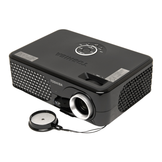
Names of each part on the main unit Back Name (1) Lens (2) Infrared remote sensor (3) Foot adjuster release button : Press to set up or stow the foot adjuster. (4) Air exhaust (5) Air intake (6) Control panel (7) Zooming ring (8) Speaker (9) AC IN socket (10) Rear panel (11) Antitheft lock slot (12) Tilt adjuster... -
Page 17: Names Of Each Part On The Control Panel
Names of each part on the control panel Name Control panel (1) VOL +/- button (2) ENTER button (3) KEYSTONE +/- button (4) Selection buttons (5) INPUT button (6) ON/STANDBY button/ indicator (7) MENU button (8) TEMP indicator (9) LAMP indicator (7) (8) (9) (5) : Main Function : Adjusts the volume. -
Page 18: Names Of Each Part On The Remote Control
Names of each part on the remote control Name (1) VOL +/- button (2) ENTER button (3) KEYSTONE +/- button (4) Selection buttons (5) INPUT button (6) ON/STANDBY button (7) MENU button (8) FREEZE button (9) RESIZE buttons (10) Auto-Set button (11) MUTE button Remote control transmitter (10) (11) : Main Function... -
Page 19: Parts On The Rear Panel
Parts on the rear panel Name (1) COMPUTER IN terminal (2) S-VIDEO terminal (3) VIDEO terminal (4) AUDIO IN terminal (5) AUDIO OUT terminal (6) MONITOR terminal (7) CONTROL terminal (8) AC IN socket (9) Antitheft lock slot (2) (3) (4) : Main Function : Input analog RGB signal from a computer or other source, or a component video signal (Y/P... -
Page 20: Preparing And Using The Remote Control
Preparing and using the remote control ■ Loading a coin cell battery into the remote control j Remove the battery holder. Hold down the side release firmly and pull out the battery holder. k Load a coin cell battery (CR2025). Be sure to align the plus and minus ends of the battery properly. l Replace the battery holder back into the remote control. -
Page 21: Placement
Placement Placement Styles As shown in the figures below, this device can be placed in 4 different styles. The factory setting is “floor-mounted front projection.” Set the [Projection mode] in the Default setting menu , in accordance with your needs. p.34 Floor-mounted front projection Floor-mounted rear projection Ceiling-mounted front projection Ceiling-mounted rear projection... -
Page 22: Projection Distance And Size
Placement (Continued) Projection Distance and Size Use the figures, tables, and formulas below to determine the projection size and projection distance. (Projection sizes are approximate values for full-size picture with no keystone adjustment.) As seen from above Screen As seen from the side Lens center a is the distance (cm, feet) between the lens and the screen, and corresponds to a range of 1 m to 11.88m (3.28 ft. -
Page 23: Connection
Connection Before connection • Read the owner’s manual of the device you are connecting to the projector. • Some computers cannot be used with or connected to this projector. Check for an RGB output terminal, supported signal • Turn off the power of both devices before connecting. •... -
Page 24: Turning The Power On And Off
■ Connecting the power cord Insert the power cord connector into the AC IN socket of the projector. Insert the power cord plug into a wall or other power outlet. ■ Removing the lens cover ■ Turning the power on Press the ON/STANDBY button. -
Page 25: Turning The Power Off
■ Turning the power off Press the ON/STANDBY button. A message appears on the screen, confirming that you wish to shut off the power. To shut off the power, press the ON/STANDBY button again. If you do not wish to shut off the power, wait for a while without conducting any operations. -
Page 26: Basic Operations
Basic operations Turn on the power. Turn on the power by following the instructions in “Turning the power on” Select the language (When using the first time). When the projector is used for the first time after purchase, the start menu for lan- guage (to display the menus and messages on screen) and configuration is displayed in English. -
Page 27: Adjusting The Screen Size And Focus
Projector placement angle adjustments The placement angle and the height of the projected image can be adjusted by the foot adjuster. j Lift up the front of the projector to the desired angle, then press the foot adjuster release button. The foot adjuster extends. Release the but- ton to lock the position. -
Page 28: Using Handy Features
Using handy features ■ Using auto setting This function automatically sets up the projector to the optimum state. It sets up sampling phase, frequency and screen position for each type of the input signal by using simple operations. Press the remote control’s AUTO SET button. icon will appear during processing. Notes •... -
Page 29: Cutting Off The Picture And Sound Temporarily (Mute)
■ Cutting off the picture and sound temporarily (Mute) When you want to project the images of another projector, overhead projector, etc. temporarily, this projector’s images and sound can be turned off. Press the remote control’s MUTE button. The picture and sound are cut off. (The Mute function is released when pressing the MUTE button again.) Notes •... -
Page 30: Resizing Image
Using handy features (Continued) ■ Resizing image The projected image can be resized (zoomed in/out). Press the remote control’s RESIZE Each time you press the RESIZE pressing. To zoom out, press the remote control’s RESIZE button. Each time you press the RESIZE down. You can keep pressing. (However, the image cannot be smaller than the original size.) To move the area to zoom in, use the You can keep pressing. -
Page 31: Using The Menus
Using the menus You can call up on-screen menus, and conduct a number of adjustments and settings using the operation buttons on the control panel (main unit side) and remote control. p.18 ■ How to use the menus The menu shown below is for operation instructions purposes and might differ from the actual display. -
Page 32: The Image Adjustment Menu
Using the menus (Continued) ■ The image adjustment menu Use this menu to set or adjust image-related items. Items that can be set or adjusted are marked “Yes”, and those that cannot are marked “No”. (When an item is masked, it indi- cates that you cannot select for the current input.) Item Picture mode Toggle the picture mode with Bright/Standard/True color(RGB) -
Page 33: The Display Setting Menu
[Background] • TOSHIBA is set for [Logo] by factory setting. Description (Blue) Lower... -
Page 34: The Default Setting Menu
Using the menus (Continued) ■ The default setting menu This menu shows placement status and other settings. Item Projection Sets projection mode in accordance with Placement Style. mode Auto input Sets whether the input source with signals is only selected or not. search Language Select one of the languages below to use for displaying the menu and messages English/Français/Deutsch/Italiano/Español/Português/ Svenska/Türkçe/Română/... -
Page 35: Displaying Information (Status Display)
■ Displaying Information (Status display) This displays information about the input signal, lamp use time, etc. Item Input Input source name Resolution Resolution (in dots) Video mode Color method of video signal Picture mode Picture mode setting Lamp time Time of lamp use Version Firmware version Notes... -
Page 36: Maintenance
About lamp The product’s light source is a mercury lamp that lights at increased internal pressure. Be sure to fully understand the following characteristics of the lamp and handle it with extreme care. • The lamp may burst with a loud noise due to impact or deterioration, or fail to light at the expiration of its life. -
Page 37: Lamp Replacement
This is characteristic of a lamp, and is not malfunction. (The lifetime of the lamp depends on condition of use.) If this happens, replace it with a new one. WARNING • If the projector is mounted on the ceiling, it is recommended to use your Toshiba dealer- ship when the lamp has to be exchanged. Uncovering the lamp while the projector is mounted on a ceiling may lead to a danger of damage from falling pieces of glass if the lamp is broken. - Page 38 Lamp replacement (Continued) Mount the new lamp. Align the orientation, press down the new lamp until the bottom is reached, and lock in place using the two lamp locking screws. Replace the lamp cover. Align the cover and press it in. Then replace the screws you removed in step until the lamp cover is no longer loose.
-
Page 39: Lens And Main Unit Cleaning
Lens and main unit cleaning WARNING • Request cleaning and maintenance of a ceiling-mounted unit from your projector dealership. Attempting to clean or replace the lamp in a high location by yourself may cause you to fall, resulting in injury. ■ Lens cleaning • Clean the lens with a commercially available blower and/or lens cleaner. •... -
Page 40: Trouble Indications
Trouble indications The indicator lights to inform you of interminal abnormalities. No power ⇒ Problem with projector (Off) Lamp went out during use, or won’t come on ⇒ Lamp temperature is high so that it is difficult to turn on, the lifetime of (Red lit) (Red lit) Power went out during use ⇒... -
Page 41: Before Calling Service Personnel
Before calling service personnel If you think something is wrong, check the followings before contacting customer service. Please see “Trouble indications” If This Happens No power • Is the power cord plugged in? Is it connected to the projector? • Is the lamp cover attached properly? Power goes out •... -
Page 42: Specifications
■ List of general specifications Item Consumption Power Weight External Dimensions (including protruding parts) Cabinet material Conditions for usage environ- ment Display pixels Picture elements Lens Lamp Projection screen size Projection distance Speaker CONTROL terminal COMPUTER(Y/P IN terminal VIDEO terminal MONITOR terminal AUDIO OUT terminal Notes •... -
Page 43: List Of Supported Signals (Rgb Signals)
■ List of supported signals (RGB signals) This projector supports the following RGB signals. Note, however, that depending on the computer model, the screen may show flicker or streaking. Please adjust the projector if this happens. Resolution VGA_60 VGA_72 640x480 VGA_75 VGA_85 720x400_70... -
Page 44: List Of Supported Signals (Component Signals)
Specifications (Continued) ■ List of supported signals (Component signals) Signal format 480i (525i)@60Hz 480p (525p)@60Hz 576i (625i)@50Hz 576p (625p)@50Hz 720p (750p)@60Hz 720p (750p)@50Hz 1080i (1125i)@60Hz 1080i (1125i)@50Hz ■ List of supported signals (Video, S-Video signals) Video mode NTSC SECAM PAL-M PAL-N PAL-60 NTSC4.43 ■ Pin assignment of COMPUTER IN & MONITOR terminals Mini D sub 15 Pin connector Input Signal •... -
Page 45: Control Terminal
■ CONTROL terminal ● Pin assignment D-Sub 9 pin connector Notes • Contact your dealer for control cable and commands. Pin No. Signal Name ∗ Sending data Receiving data ∗ Signal ground ∗ ∗ ∗ ∗ ∗ Do not connect anything. Description...