Table of Contents
Advertisement
Quick Links
Installer:
Leave this manual with the appliance.
Consumer: Retain this manual for future reference.
WARNING: If the information in these instructions
are not followed exactly, a fire or explosion may
result causing property damage, personal injury or
loss of life.
— Do not store or use gasoline or other flammable
vapors and liquids in the vicinity of this or any
other appliance.
— WhAT TO DO If yOU SMELL GAS
•
Do not try to light any appliance.
•
Do not touch any electrical switch; do not use
any phone in your building.
•
Immediately call your gas supplier from a
neighbor's phone. follow the gas supplier's
instructions.
•
If you cannot reach your gas supplier, call the
fire department.
— Installation and service must be performed by a
qualified installer, service agency or the gas sup-
plier.
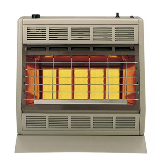
INSTALLATION INSTRUCTIONS
OWNER'S MANUAL
SR-30T ShOWN
AND
UNVENTED
ROOM hEATER
MODELS
SR-10T-4
SR-18T-4
This is an unvented gas-fired heater. It uses air (oxy-
gen) from the room in which it is installed. Provisions
for adequate combustion and ventilation air must be
provided. Refer to page 6.
WARNING: If not installed, operated and maintained
in accordance with the manufacturer's instructions,
this product could expose you to substances in fuel
or from fuel combustion which can cause death or
serious illness.
WATER VAPOR: A By-PRODUCT Of UNVENTED ROOM
hEATERS
Water vapor is a by-product of gas combustion. An
unvented room heater produces approximately one (1)
ounce (30ml) of water for every 1,000 BTU's (.3KW's)
of gas input per hour. Refer to page 6.
SR-30T-4
Page 1
Advertisement
Table of Contents

Related Manuals for Empire Heating Systems SR-10T-4


Summary of Contents for Empire Heating Systems SR-10T-4
- Page 1 INSTALLATION INSTRUCTIONS OWNER’S MANUAL UNVENTED ROOM hEATER MODELS SR-10T-4 SR-18T-4 SR-30T-4 SR-30T ShOWN Installer: Leave this manual with the appliance. This is an unvented gas-fired heater. It uses air (oxy- Consumer: Retain this manual for future reference. gen) from the room in which it is installed. Provisions for adequate combustion and ventilation air must be provided.
-
Page 2: Table Of Contents
TABLE Of CONTENTS SECTION PAGE Important Safety Information .................3 Safety Information for Users of LP Gas ............4 Introduction ....................5 Specifications ....................5 Water Vapor: A By-Product of Unvented Room Heaters .......6 Provisions for Adequate Combustion and Ventilation Air ......6 Gas Supply ....................7 SR-10T Clearances ..................8 SR-18T Clearances ..................9 SR-30T Clearances ..................9... -
Page 3: Important Safety Information
IMPORTANT SAfETy INfORMATION ThIS IS A hEATING APPLIANCE DO NOT OPeRATe THIS APPLIANCe WITHOUT FRONT PANeL INSTALLeD. • Due to high surface temperatures, keep children, clothing DANGER: Indicates a hazardous situation which, if not and furniture away. avoided, will result in death or serious injury. •... -
Page 4: Safety Information For Users Of Lp Gas
SAfETy INfORMATION fOR USERS Of LP-GAS Propane (LP-Gas) is a flammable gas which can cause fires with the members of your household. Someday when there and explosions. In its natural state, propane is odorless and may not be a minute to lose, everyone’s safety will depend colorless. -
Page 5: Introduction
INTRODUCTION Instructions to Installer Qualified Installing Agency 1. Installer must leave instruction manual with owner after Installation and replacement of gas piping, gas utilization equipment installation. or accessories and repair and servicing of equipment shall be 2. Installer must have owner fill out and mail warranty card supplied performed only by a qualified agency. -
Page 6: Water Vapor: A By-Product Of Unvented Room Heaters
WATER VAPOR: A By-PRODUCT Of UNVENTED ROOM hEATERS Water vapor is a by-product of gas combustion. An unvented room The following steps will help insure that water vapor does not heater produces approximately one (1) ounce (30ml) of water for become a problem. -
Page 7: Gas Supply
GAS SUPPLy A gas valve and ground joint union should be installed in the gas The gas line can be routed either through the floor or wall. The gas line upstream of the gas control to aid in servicing. It is required by line opening should be made at this time. -
Page 8: Sr-10T Clearances
SR-10T CLEARANCES When facing the front of the appliance the following minimum clearances to combustible construction must be maintained. Left side 6 inches (152mm). Right side 6 inches (152mm). Do not install in alcove or closet. Rear wall 0 inches (0mm). Ceiling 24 inches (610mm). Minimum vertical clearance from a projection above the appliance (shelves, window sills, etc.) 14 inches (356mm). -
Page 9: Sr-18T Clearances
SR-18T CLEARANCES When facing the front of the appliance the following minimum clearances to combustible construction must be maintained. Left side 6 inches (152mm). Right side 6 inches (152mm). Do not install in alcove or closet. Rear wall 0 inches (0mm). Ceiling 36 inches (914mm). Minimum vertical clearance from a projection above the appliance (shelves, window sills, etc.) 36 inches (914mm). -
Page 10: Wall Mount Installation
WALL MOUNT INSTALLATION Refer to Figures 7, 8 and 9 for measurements in order to locate (4) mounting holes on wall. Figures 7, 8 and 9 are the front views (613mm) of the heaters. (511mm) (51) (51) 1. Remove lower louver from casing assembly (2 screws). 2. -
Page 11: Optional Floor Stand Installation
4. Mount heater onto the (4) screwheads and complete tightening the screwheads to the plastic expansion anchors. Attention! Use the following steps to properly align the upper louver and the reflector with the heat shield. a. When replacing upper louver, be sure the bottom lip of upper louver goes behind the heat shield. -
Page 12: Lighting Instructions
LIGhTING INSTRUCTIONS FOR YOUR SAFeTY ReAD BeFORe LIGHTING WARNING: If you do not follow these instructions exactly, a fire or explosion may result causing property damage, personal injury or loss of life. This appliance has a pilot which must be lighted by hand. C. -
Page 13: Main Burner Flame Characteristics
MAIN BURNER fLAME ChARACTERISTICS SR-10T, SR-18T and SR-30T Main Burner Flame (Figure12) Disconnect supply tubing from orifice holder(s). The main burner flame will have a red-orange glow over the surface 10. Remove orifice holder from venturi of main burner assembly of the ceramic plaques. -
Page 14: Pilot Flame Characteristics
PILOT fLAME ChARACTERISTICS The correct flame will be blue and will extend beyond the thermo- Blow air pressure through the holes indicated by the arrows. couple. The flame will surround the thermocouple just below the This will blow our foreign materials such as dust, lint and spider tip. -
Page 15: Appliance Maintenance
APPLIANCE MAINTENANCE 10. Remove gas valve bracket from casing assembly (4 screws to Removing Pilot/Thermocouple from Main Burner Assembly be removed are located on casing assembly back). Attention: The thermocouple CAN NOT be replaced as an individual 11. Remove hydraulic thermostat bulb from thermostat bulb clip item. -
Page 16: Troubleshooting
TROUBLEShOOTING 1. Spark electrode does not produce spark. d. Pilot flame not surrounding thermocouple - clean pilot, see a. Spark electrode broken - replace. Page 14. b. Ignitor wire may not be attached to spark electrode - e. Inlet gas pressure too low, contact gas supplier. attach. -
Page 17: Sr-18T And Sr-30T Parts List
PARTS LIST SR-18T SR-30T PLEASE NOTE: When ordering parts, it is very important that part number and description of part coincide. INDEX INDEX PART PART NO. DESCRIPTION DESCRIPTION 13348 CASING SIDe ASSeMBLY - LeFT 13348 CASING SIDe ASSeMBLY - LeFT SR-090 CASING BACK SR-041... -
Page 18: Sr-10T Parts View
PARTS VIEW SR-10T Page 18 35964-0-0615... -
Page 19: Sr-18T Parts View
PARTS VIEW SR-18T 35964-0-0615 Page 19... -
Page 20: Sr-30T Parts View
PARTS VIEW SR-30T Page 20 35964-0-0615... -
Page 21: Optional Blower Installation Instructions
OPTIONAL BLOWER INSTALLATION INSTRUCTIONS SRB-18T and SRB-30T for Unvented Room heaters SR-18T and SR-30T INSTALLING OPTIONAL BLOWER SRB-18T OR SRB-30T 12. With the heater standing upright, position the air discharge If heater is installed onto the wall, in order to install the optional opening of the blower housing downward. - Page 22 oPTIonAL BLoWER InSTALLATIon InSTRUCTIonS (continued) Wiring The appliance, when installed, must be electrically grounded in ac- cordance with local codes or, in the absence of local codes, with the National Electrical Code, ANSI/NFPA 70, if an external electrical source is utilized. This appliance is equipped with a three-prong [ground- ing] plug for your protection against shock hazard and should be plugged directly into a properly grounded three-prong receptacle.
-
Page 23: Master Parts Distributor List
MASTER PARTS DISTRIBUTOR LIST To Order Parts Under Warranty, please contact your local empire dealer. See the dealer locator at www.empirecomfort. com. To provide warranty service, your dealer will need your name and address, purchase date and serial number, and the nature of the problem with the unit. - Page 24 empire Comfort Systems Inc. EMPIRE EMPIRE 918 Freeburg Ave. Belleville, IL 62220 If you have a general question about our products, please e-mail us at info@empirecomfort.com. If you have a service or repair question, please contact your dealer. Comfort Systems www.empirecomfort.com Page 24 35964-0-0615...