Table of Contents
Troubleshooting

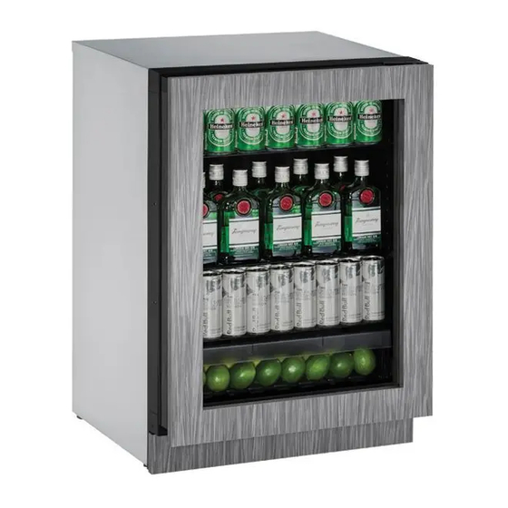
Related Manuals for U-Line U2224RGLINT00B


Summary of Contents for U-Line U2224RGLINT00B
- Page 1 USER GUIDE & SERVICE MANUAL SAFETY • INSTALLATION & INTEGRATION • OPERATING INSTRUCTIONS • MAINTENANCE • SERVICE RIGHT PRODUCT. RIGHT PLACE. RIGHT TEMPERATURE. SINCE 1962. 2000 Series 2224RGL 24" Glass Door Refrigerator • •...
-
Page 2: Table Of Contents
USER GUIDE u-line.com SAFETY • INSTALLATION & INTEGRATION • OPERATING INSTRUCTIONS • MAINTENANCE • SERVICE Contents Intro Cleaning Condenser Extended Non-Use Safety Safety and Warning Service Disposal And Recycling Troubleshooting Wire Diagram Installation Product Liability Environmental Requirements Warranty Claims Electrical... - Page 3 1. U-Line Customer Care must be contacted immediately at +1.800.779.2547. 2. Service or repairs performed on the unit without prior written approval from U-Line is not permitted. If the unit has been altered or repaired in the field without prior written approval from U-Line, claims will not be eligible.
-
Page 4: Safety And Warning
USER GUIDE u-line.com SAFETY • INSTALLATION & INTEGRATION • OPERATING INSTRUCTIONS • MAINTENANCE • SERVICE Safety and Warning DANGER NOTICE This unit contains R600a (Isobutane) which is a Please read all instructions before installing, flammable hydrocarbon. It is safe for regular operating, or servicing the appliance. -
Page 5: Disposal And Recycling
USER GUIDE u-line.com SAFETY • INSTALLATION & INTEGRATION • OPERATING INSTRUCTIONS • MAINTENANCE • SERVICE Disposal and Recycling DANGER RISK OF CHILD ENTRAPMENT. Before you throw away your old refrigerator or freezer, take off the doors and leave shelves in place so children may not easily climb inside. -
Page 6: Environmental Requirements
USER GUIDE u-line.com SAFETY • INSTALLATION & INTEGRATION • OPERATING INSTRUCTIONS • MAINTENANCE • SERVICE Environmental Requirements This model is intended for indoor/interior applications only and is not to be used in installations that are open/ exposed to natural elements. - Page 7 USER GUIDE u-line.com Electrical WARNING SHOCK HAZARD — Electrical Grounding Required. Never attempt to repair or perform maintenance on the unit until the electricity has been disconnected. Never remove the round grounding prong from the plug and never use a two-prong grounding adapter.
-
Page 8: Cutout Dimensions
SAFETY • INSTALLATION & INTEGRATION • OPERATING INSTRUCTIONS • MAINTENANCE • SERVICE Cutout Dimensions PREPARE SITE Your U-Line product has been designed exclusively for a built-in installation. When built-in, your unit does not require additional air space for top, sides, or rear. -
Page 9: Product Dimensions
USER GUIDE u-line.com SAFETY • INSTALLATION & INTEGRATION • OPERATING INSTRUCTIONS • MAINTENANCE • SERVICE Product Dimensions Not Including Handle 23-7/16" (590 mm) 33-11/16" to 34-11/16" (856 mm to 881 mm) 17-3/4" (450 mm) 3-5/16" (84 mm) Product Dimensions 1... -
Page 10: Side By Side Installation
USER GUIDE u-line.com SAFETY • INSTALLATION & INTEGRATION • OPERATING INSTRUCTIONS • MAINTENANCE • SERVICE Side-by-Side Installation Hinge-by-Hinge Installation (Mullion) When installing two units hinge-by-hinge, 13/16" (22 mm) OTHER SITE REQUIREMENTS is required for integrated models. Additional space may be Side-by-Side Installation needed for any knobs, pulls or handles installed. -
Page 11: Anti-Tip Bracket
USER GUIDE u-line.com SAFETY • INSTALLATION & INTEGRATION • OPERATING INSTRUCTIONS • MAINTENANCE • SERVICE Anti-Tip Bracket SIDE MOUNT Left Hinged Cabinet Right Hinged Cabinet CAUTION The anti-tip bracket must be installed to prevent the unit from tipping when doors are fully opened or excess weight is placed on the front of the unit. -
Page 12: General Installation
USER GUIDE u-line.com SAFETY • INSTALLATION & INTEGRATION • OPERATING INSTRUCTIONS • MAINTENANCE • SERVICE General Installation INSTALLATION 1. Plug in the power/electrical cord. LEVELING INFORMATION 1. Use a level to confirm 2. Gently push the unit into position. Be careful not to the unit is level. -
Page 13: Integrated Panel Dimensions
USER GUIDE u-line.com SAFETY • INSTALLATION & INTEGRATION • OPERATING INSTRUCTIONS • MAINTENANCE • SERVICE Integrated Panel Dimensions Integrated Frame Dimensions Metric measurements rounded and optimized. 3/4" BACK SURFACE MUST HAVE AMPLE FLAT SURFACE (20 mm) INTEGRATED FRAME TO MOUNT OVERLAY FRAME FLAT AND WITHOUT... - Page 14 3-1/2" (89 mm) NOTE: Many cabinet manufacturers provide a ready solution for a handleless, integrated design that can be easily applied to your U-Line 3000 Series model. Consult your cabinet manufacturer for applicable design and Wooden Insert installation details. The cabinet manufacturer’s solution to...
- Page 15 USER GUIDE u-line.com SAFETY • INSTALLATION & INTEGRATION • OPERATING INSTRUCTIONS • MAINTENANCE • SERVICE Handleless Integrated Frame Dimensions 1/8" (3 mm) Top Design 1/4" (6 mm) 7/8" (22 mm) Ref. 2-3/8" R 5/8" (60 mm) (R 16 mm) 23-1/2"...
- Page 16 USER GUIDE u-line.com SAFETY • INSTALLATION & INTEGRATION • OPERATING INSTRUCTIONS • MAINTENANCE • SERVICE EXTENDED INTEGRATED FRAME NOTICE Due to differences in surrounding cabinetry the panel may not perfectly align with door. The procedure below is designed to provide a finished panel that seamlessly integrates with surrounding cabinetry.
- Page 17 USER GUIDE u-line.com SAFETY • INSTALLATION & INTEGRATION • OPERATING INSTRUCTIONS • MAINTENANCE • SERVICE Integrated Panel/Integrated Frame Integrated Panel U-Line U-Line Cabinet Unit Unit 3-5/16" (89 mm) 3-5/16" (89 mm) > 3-5/16" (> 89 mm) 4-5/16" (114 mm) 4-5/16" (114 mm)
- Page 18 USER GUIDE u-line.com SAFETY • INSTALLATION & INTEGRATION • OPERATING INSTRUCTIONS • MAINTENANCE • SERVICE Extended Integrated Frame Dimensions 3/4" BACK SURFACE MUST HAVE AMPLE FLAT SURFACE (20 mm) TO MOUNT OVERLAY FRAME FLAT AND WITHOUT INTERFERENCE 23-1/2" (595 mm) 32-7/8"...
-
Page 19: Integrated Grille / Plinth Dimensions
3. Apply double sided tape to the backside of the integrated grill (plinth strip/base fascia). Use the diagram below for reference. U-Line recommends ™ ™ tape, a high strength bonding tape. -
Page 20: Integrated Panel Installation
Clamp clamps. A robust NOTICE tape may also be If panel requires additional adjustment after used. U-Line removing clamps, slightly loosen each screw and recommends the adjust panel as necessary. Tighten screws upon use of bar clamps Door/Drawer completion. -
Page 21: Grille / Plinth Installation
USER GUIDE u-line.com SAFETY • INSTALLATION & INTEGRATION • OPERATING INSTRUCTIONS • MAINTENANCE • SERVICE Grille - Plinth Installation REMOVING AND INSTALLING GRILLE (PLINTH STRIP/BASE FASCIA) WARNING Disconnect electric power to the unit before removing the grille (plinth strip/base fascia). -
Page 22: Door Swing
USER GUIDE u-line.com SAFETY • INSTALLATION & INTEGRATION • OPERATING INSTRUCTIONS • MAINTENANCE • SERVICE Door Swing Wall For Integrated models that are installed adjacent to a wall, 1/2" (13 mm) 1/2" (13 mm) clearance is recommended from wall on hinge side to allow the door to open 90°. -
Page 23: Door Stop
3. Once cover is removed, slide hinge pin into hole as shown. Pin should slide into place, stopping the door at Your U-Line unit was shipped to you with the optional 90° 90°; if the pin does not go into the hole shown, hold pin. -
Page 24: Door Adjust
USER GUIDE u-line.com SAFETY • INSTALLATION & INTEGRATION • OPERATING INSTRUCTIONS • MAINTENANCE • SERVICE Door Adjustments DOOR ALIGNMENT AND ADJUSTMENT Align and adjust the door if it is not level or is not sealing properly. If the door is not sealed, the unit may not cool... - Page 25 USER GUIDE u-line.com SAFETY • INSTALLATION & INTEGRATION • OPERATING INSTRUCTIONS • MAINTENANCE • SERVICE 3. Using T-25 Torx bit loosen screw #1 and remove screw #2 on top and bottom hinge. Slide and remove the door from unit. Completely remove screw #1 on top and bottom.
-
Page 26: First Use
USER GUIDE u-line.com SAFETY • INSTALLATION & INTEGRATION • OPERATING INSTRUCTIONS • MAINTENANCE • SERVICE First Use All U-Line controls are preset at the factory. Initial startup requires no adjustments. NOTICE U-Line recommends allowing the unit to run overnight before loading with product. -
Page 27: Control Operation
USER GUIDE u-line.com SAFETY • INSTALLATION & INTEGRATION • OPERATING INSTRUCTIONS • MAINTENANCE • SERVICE Control Operation CONTROL FUNCTION GUIDE FUNCTION COMMAND DISPLAY/OPTIONS ON/OFF Press and release Unit will immediately turn ON or OFF. Press and release to leave interior Toggle lights Glass door wine and beverage centers only. -
Page 28: Sabbath Mode
The unit will still maintain internal temperatures and set points. View a full list of Star-K certified U-Line units at www.star-k.org. To enable Sabbath Mode: 1. Press (4) and hold for ten seconds and release (the °F/°C symbol will flash briefly at the end of the ten... -
Page 29: Airflow And Product Loading
Do not install the unit behind a door. When properly loaded, your U-Line unit will store up to 172 (12 oz. [330 ml]) cans or 114 (12 oz. [330 ml]) bottles. -
Page 30: Interior Shelves
USER GUIDE u-line.com SAFETY • INSTALLATION & INTEGRATION • OPERATING INSTRUCTIONS • MAINTENANCE • SERVICE Interior Shelves CAUTION REMOVING AND INSTALLING GLASS SHELVES Clips MUST be installed with the ribbed side Adjusting Interior Shelves down. Failure to do so may result in shelf or unit Models equipped with glass shelves have an adjustable damage. -
Page 31: Maintenance
USER GUIDE u-line.com SAFETY • INSTALLATION & INTEGRATION • OPERATING INSTRUCTIONS • • SERVICE MAINTENANCE Cleaning Integrated Models To clean integrated panels, use household cleaner per the EXTERIOR CLEANING cabinet manufacturer’s recommendation. Stainless Models Stainless door panels and handles can discolor when... - Page 32 USER GUIDE u-line.com SAFETY • INSTALLATION & INTEGRATION • OPERATING INSTRUCTIONS • • SERVICE MAINTENANCE NOTICE The drain pan was not designed to capture the water created when manually defrosting. To prevent water from overflowing the drain pan and possibly damaging water sensitive flooring, the unit must be removed from cabinetry.
-
Page 33: Cleaning Condenser
USER GUIDE u-line.com SAFETY • INSTALLATION & INTEGRATION • OPERATING INSTRUCTIONS • MAINTENANCE • SERVICE Cleaning Condenser INTERVAL - EVERY SIX MONTHS To maintain operational efficiency, keep the front grille (plinth strip/base fascia) free of dust and lint, and clean the condenser when necessary. -
Page 34: Extended Non-Use
If the unit will be exposed to temperatures of 40°F (5°C) or less, the steps above must be followed. For questions regarding winterization, please call U-Line at +1.800.779.2547. CAUTION Damage caused by freezing temperatures is not covered by the warranty. -
Page 35: Troubleshooting
• Evaporator: Refrigerant flowing through an evaporator may sound like boiling liquid. BEFORE CALLING FOR SERVICE If you think your U-Line product is malfunctioning, read • Condenser Fan: Air moving through a condenser may the CONTROL OPERATION section to clearly understand be heard. - Page 36 USER GUIDE u-line.com SAFETY • INSTALLATION & INTEGRATION • OPERATING INSTRUCTIONS • MAINTENANCE • SERVICE 6. After 24 hours, check the temperature of the water. If Problem Possible Cause and Remedy required, adjust the temperature control in a small Digital Display A factory test mode may be enabled.
-
Page 37: Wire Diagram
USER GUIDE u-line.com SAFETY • INSTALLATION & INTEGRATION • OPERATING INSTRUCTIONS • MAINTENANCE • SERVICE Wire Diagram Wire Diagram 1... -
Page 38: Product Liability
The part that caused the damage must be returned to U-Line in its entirety. The part must be clearly labeled with the serial number of the unit it was removed from, the date, and the servicer who removed the part. -
Page 39: Warranty Claims
USER GUIDE u-line.com SAFETY • INSTALLATION & INTEGRATION • OPERATING INSTRUCTIONS • MAINTENANCE • SERVICE Warranty Claims warranty status. We also accept the following information to verify warranty status: The following information defines the parameters for filing a warranty claim: •... -
Page 40: Parts
Parts U-2224RGLINT-00B Item Description U-Line P/N Anti tip bracket w/screws 80-54012-00 Back panel 80-54086-00 Compressor electricals only 80-54149-00 Compressor w/electricals 80-54150-00 Condenser 80-54043-00 Condenser fan w/screws 80-54014-00 Crisper 80-54044-00 Display module 80-54007-00 Door assembly w/o hinges 80-54038-00 10 Door gasket... -
Page 41: Ordering Replacement Parts
Warranty parts will be shipped at no charge after U-Line confirms warranty status. Please provide the model, serial number, part number and part description. Some parts will require color or voltage information. -
Page 42: System Diagnosis Guide
USER GUIDE u-line.com SAFETY • INSTALLATION & INTEGRATION • OPERATING INSTRUCTIONS • MAINTENANCE • SERVICE System Diagnosis Guide REFRIGERATION SYSTEM DIAGNOSIS GUIDE System Suction Suction Compressor Condenser Capillary Evaporator Wattage Condition Pressure Line Discharge Tube Normal Normal Slightly below Very hot... -
Page 43: Compressor Specifications
USER GUIDE u-line.com SAFETY • INSTALLATION & INTEGRATION • OPERATING INSTRUCTIONS • MAINTENANCE • SERVICE Compressor Specifications OVERLOAD PROTECTOR STARTING RELAY DANGER Electrocution can cause death or serious injury. Burns from hot or cold surfaces can cause serious injury. Take precautions when servicing... -
Page 44: Troubleshooting Extended
Included in this section are some diagnostic tips and of Solenoid Valves: An occasional clicking sound may be course, if additional help is required please contact the heard as solenoid valves are operated. U-Line Corp, “Customer Care Facility” at +1.800.779.2547 for assistance. Troubleshooting - Extended 1... - Page 45 USER GUIDE u-line.com SAFETY • INSTALLATION & INTEGRATION • OPERATING INSTRUCTIONS • MAINTENANCE • SERVICE TROUBLESHOOTING GUIDE Concern Potential Causes Suggested Remedy Not Cooling Compressor overheating Verify proper air flow through condenser. Is condenser clean? Confirm condenser fan operation. Confirm proper compressor operating voltage. Use #19, Component Testing in Service Mode.
- Page 46 USER GUIDE u-line.com SAFETY • INSTALLATION & INTEGRATION • OPERATING INSTRUCTIONS • MAINTENANCE • SERVICE MAIN CONTROL Testing The Main Control The main control board is very robust and is rarely the If the main control is suspected of being faulty, the cause of system issues.
- Page 47 USER GUIDE u-line.com SAFETY • INSTALLATION & INTEGRATION • OPERATING INSTRUCTIONS • MAINTENANCE • SERVICE REED SWITCH A reed switch is used to monitor door state. When the door is closed magnetic force pulls the reed to its contact and closes the circuit which turns the light and display off.
- Page 48 USER GUIDE u-line.com SAFETY • INSTALLATION & INTEGRATION • OPERATING INSTRUCTIONS • MAINTENANCE • SERVICE Control Operation - Service UI BUTTON LAYOUT Hidden Button -Accesses Service Menu -No LED directly above. All LEDs turn on with button activation except #7.
-
Page 49: Control Quick Guide
USER GUIDE u-line.com SAFETY • INSTALLATION & INTEGRATION • OPERATING INSTRUCTIONS • MAINTENANCE • SERVICE CONTROL FUNCTION QUICK GUIDE FUNCTION COMMAND DISPLAY/OPTIONS ON/OFF Press and release Unit will immediately turn ON or OFF Press and release to leave interior light... - Page 50 USER GUIDE u-line.com SAFETY • INSTALLATION & INTEGRATION • OPERATING INSTRUCTIONS • MAINTENANCE • SERVICE SERVICE MODE GUIDE SERVICE MODE GUIDE 1. THERMISTOR 1 — ZONE Service Mode Menu Item This shows the pure thermistor reading with no View thermistor #1 (no offsets) offsets taken into account.
- Page 51 USER GUIDE u-line.com SAFETY • INSTALLATION & INTEGRATION • OPERATING INSTRUCTIONS • MAINTENANCE • SERVICE 14. VIEW ERROR LOG 20. MODEL NUMBER INDICATOR A list of the errors in the order they occurred will Displays the two-digit model number of the scroll once on the display.
- Page 52 MODEL NUMBER 1. Disconnect the unit from power source. 2. Push and hold the U-Line button. 3. While still holding the U-Line button, plug the unit into the appropriate power source. 4. When the flashing digits appear (3-5 seconds), use the up and down arrow buttons to select the appropriate model number*.
- Page 53 USER GUIDE u-line.com SAFETY • INSTALLATION & INTEGRATION • OPERATING INSTRUCTIONS • MAINTENANCE • SERVICE Control Operation - Service 6...
-
Page 54: Thermistor
USER GUIDE u-line.com SAFETY • INSTALLATION & INTEGRATION • OPERATING INSTRUCTIONS • MAINTENANCE • SERVICE Thermistors Thermistor three (Ambient): Located in the base of the unit (secured to the Thermistors are used for various temperature readings. condenser). It is used to monitor the ambient temperature Thermistors provide reliable temperature readings using a within the base compartment. - Page 55 USER GUIDE u-line.com SAFETY • INSTALLATION & INTEGRATION • OPERATING INSTRUCTIONS • MAINTENANCE • SERVICE Thermistor Resistance Data Nominal Resistance Temp (F) Temp (C) (OHMS)* 169157 121795 88766 65333 48614 36503 27681 21166 16330 12696 9951 7855 6246 5000 4029...
-
Page 56: Defrost
USER GUIDE u-line.com SAFETY • INSTALLATION & INTEGRATION • OPERATING INSTRUCTIONS • MAINTENANCE • SERVICE Defrost The models below have automatic or frost free design and do not require manual defrosting under normal conditions. Defrost Settings Base Model Variant(s) Compressor Run Time... -
Page 57: Remove Fan And Cover
USER GUIDE u-line.com SAFETY • INSTALLATION & INTEGRATION • OPERATING INSTRUCTIONS • MAINTENANCE • SERVICE Remove Fan and Cover 3. Disconnect power to the unit. CONVECTION COOLING 4. Remove rear cover from unit. This unit is equipped with an advanced convection cooling system. - Page 58 USER GUIDE u-line.com SAFETY • INSTALLATION & INTEGRATION • OPERATING INSTRUCTIONS • MAINTENANCE • SERVICE 13.Remove the 4 screws mounting the fan shroud to the evaporator plate. Air Flow 14.Remove and replace fan. Take special care to properly route fan wire.
-
Page 59: Warranty
One Year Limited Warranty For one year from the date of original purchase, this U-Line product warranty covers all parts and labor to repair or replace any part of the product that proves to be defective in materials or workmanship. For products installed and used for normal residential use, material cosmetic defects are included in this warranty, with coverage limited to 60 days from the date of original purchase.