Table of Contents
Advertisement
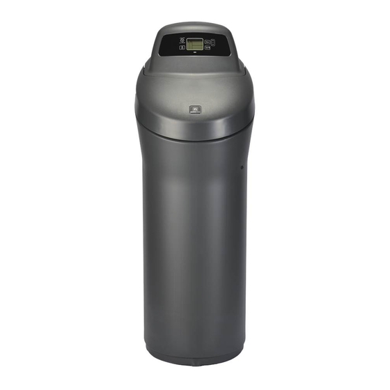
Model NSC42
How to install, operate
and maintain your Demand
Controlled Water Softener
If you have any questions or concerns when
installing, operating or maintaining your
water softener, contact us at:
info@northstarwater.com
www.northstarwater.com
or visit
System tested and certified by NSF International
against NSF/ANSI Standard 44
for hardness reduction and efficiency,
and certified to NSF/ANSI Standard 372.
System tested and certified by the
Water Quality Association against CSA B483.1.
Designed, Engineered &
Assembled in the U.S.A.
Manufactured and warranted by
North Star Water Treatment Systems
1890 Woodlane Drive
Woodbury, MN 55125
7371127 (Rev. B 9/1/18)
Advertisement
Table of Contents

Related Manuals for North Star NSC4218


Summary of Contents for North Star NSC4218
- Page 1 NSF/ANSI Standard 372. System tested and certified by the Water Quality Association against CSA B483.1. Manufactured and warranted by North Star Water Treatment Systems Designed, Engineered & 1890 Woodlane Drive 7371127 (Rev. B 9/1/18) Assembled in the U.S.A.
-
Page 2: Table Of Contents
Exploded View & Parts List ..............24-27 WATER SOFTENER WARRANTY Warrantor: North Star Water Treatment Systems, 1890 Woodlane Drive, Woodbury, MN 55125 Warrantor guarantees, to the original owner, that: One Year Full Warranty: ●... -
Page 3: Specifications & Performance Claims
Specifications & Performance Claims This model is efficiency rated. The efficiency rating is valid only at the minimum salt dose. This system has a demand initiated regeneration (D.I.R.) feature that complies with specific performance specifications intended to min- imize the amount of regenerant brine and water used in their operation. This water softener has a rated softener efficiency of not less than 3,350 grains of total hardness exchange per pound of salt (based on sodium chloride) and shall not deliver more salt than its listed rating or be operated at a sustained maximum service flow rate greater than its listed rating. -
Page 4: Inspect Shipment
Inspect Shipment The parts required to assemble and install the unit are Remove and discard (or recycle) all packing materials. included in a bag. Thoroughly check the water soften- To avoid loss of small parts, we suggest you keep the er for possible shipping damage and parts loss. -
Page 5: Before You Start
Before You Start = The water softener requires a minimum water flow of 3 gallons per minute at the inlet. Maximum allowable inlet water pressure is 125 psi. If daytime pressure is over 80 psi, nighttime pressure may exceed the maximum. Use a pressure reducing valve if necessary (Adding a pressure reducing valve may reduce the flow). -
Page 6: Installation Requirements
Installation Requirements LOCATION REQUIREMENTS PLUMBING CODES Consider all of the following when selecting an installa- All plumbing must be completed in accordance with tion location for the water softener. national, state and local plumbing codes. = Do not locate the water softener where freezing In the state of Massachusetts: The Commonwealth temperatures occur. - Page 7 Installation Requirements VALVE DRAIN REQUIREMENTS 1/4” NPT Thread Barbs for 3/8” Using the flexible drain hose (included), measure and I.D. Tubing cut to the length needed. Flexible drain hose is not Hose Clamp allowed in all localities (check your plumbing codes). If local codes do not allow use of a flexible drain hose, a Drain Hose rigid valve drain run must be used.
-
Page 8: Installation Instructions
ASSEMBLY water and salt, may cause the tank to fracture at the shim. 1. North Star models are factory assembled. During installation, unsnap and remove the top cover, continued on next page together with the salt lid, to expose the softener valve assembly. - Page 9 Installation Instructions continued from previous page Top Cover Nozzle & Venturi Assembly 2. Visually check and remove any debris from the water softener valve inlet and outlet ports. Brine Tank Salt Lid 3. Make sure the turbine assembly spins freely in the Overflow "out"...
- Page 10 Installation Instructions COLD WATER PIPE GROUNDING INSTALL SALT STORAGE TANK OVERFLOW HOSE CAUTION: The house cold water pipe (metal only) is often used as a ground for the house 1. Measure, cut to needed length and connect the 3/8” electrical system, The 3-valve bypass drain line (provided) to the salt storage tank overflow type of installation, shown in Figure 8, elbow and secure in place with a hose clamp.
- Page 11 Installation Instructions SANITIZE THE WATER SOFTENER / SANITIZE AFTER SERVICE Care is taken at the factory to keep your unit clean and If removing sanitary. Materials used to make the unit will not infect clips... or contaminate your water supply, and will not cause bacteria to form or grow.
-
Page 12: Programming The Water Softener
(see below) STATUS LIGHT PROGRAM THE SOFTENER When the North Star water softener is connected to When the power supply is plugged into the electrical electrical power, the status light on the control panel outlet, the model code (nS42) and a software version will be on or flashing, as follows: number (example: J3.9), are briefly shown in the dis-... - Page 13 Programming the Water Softener continued from previous page 1. The softener’s default recharge start time is 2:00 AM. This is normally a time of day when water is NOTE: Press buttons and quickly release to slowly not being used in the household. Hard water advance the display.
-
Page 14: Controller Features
Controller Features EXTRA RECHARGE SALT MONITOR SYSTEM Sometimes, a manually initiated recharge (regenera- The water softener has a salt monitor indicator light to tion) may be desired, or needed. Two examples are: remind you to add salt to the storage tank. NOTE: You must set salt level each time salt is You have used more water than usual (guests visit- ing) and you may run out of soft water before the... - Page 15 DOWN button to shorten the time. If no change California Efficiency Requirement is desired, continue to next step. Your North Star water softener has a “High 4. Press SELECT again to display the “97%” screen. Efficiency” feature that can be set ON or OFF.
- Page 16 Controller Features 97% FEATURE: The 97% Feature can save salt MAXIMUM DAYS BETWEEN REGENERATIONS: and water by regenerating when 97% of the soften- The electronic controller automatically determines er’s capacity has been used up. With this feature regeneration fre quency. This provides the greatest ON, the regeneration can occur at any time (when- operating efficiency and, under most conditions this ever the system has reached 97% of its capacity).
- Page 17 Controller Features WATER FLOW THROUGH THE SOFTENER TANK LIGHT To view the flow rate through the softener in liters (or A light inside the salt storage tank will come on when- gallons) per minute, press the WATER USE button. If ever you open the salt lid.
-
Page 18: Routine Maintenance
Routine Maintenance ADDING SALT BREAKING A SALT BRIDGE Sometimes, a hard crust or salt “bridge” forms in the Lift the salt lid and check the salt storage level fre- brine tank. It is usually caused by high humidity or quently. If the water softener uses all the salts before the wrong kind of salt. - Page 19 Routine Maintenance CLEANING THE NOZZLE & VENTURI PROTECT THE WATER SOFTENER FROM FREEZING A clean nozzle & venturi (See Figure 41) is a necessity for the water softener to work properly. This small If the softener is installed where it could freeze (sum- component creates the suction to move brine from the mer cabin, lake home, etc.), you must drain all water brine tank, into the resin tank.
- Page 20 Troubleshooting Guide PROBLEM CAUSE CORRECTION No soft water 1. No salt in the storage tank. Refill with salt and then use RECHARGE NOW feature. No soft water & dis- 1. Power supply unplugged at wall outlet, or Check for loss of power and correct. Reset electronic play is blank power cable disconnected from back of elec - controls and then use RECHARGE NOW feature.
-
Page 21: Troubleshooting
Troubleshooting AUTOMATIC ELECTRONIC DIAGNOSTICS This water softener has a self-diagnostic function for Motor the electrical system (except input power and/or water meter). The water softener monitors electronic com- ponents and circuits for correct operation. If a mal- function occurs, an error code appears in the display. Sensor Position Housing... - Page 22 Troubleshooting RESETTING TO FACTORY DEFAULTS Position Markers (valve in service) To reset the electronic controller to its factory default for all settings (time, hardness, etc.): 1. Press the SELECT button and hold it until the dis- play changes twice to show the flashing model code.
-
Page 23: Wiring Schematic
Wiring Schematic Back of Electronic Controller (PWA) Pwr. Tank Position/ Light Turbine Motor Power Supply 120V AC Valve 24V DC 60 Hz Motor Tank Light Position Switch Turbine Sensor FIG. 49... -
Page 24: Exploded View & Parts List
Softener Exploded View Valve Assembly See Pages 26 & 27 for parts... - Page 25 Top Cover Brinewell Assembly 7214375 (including salt level decal) Repl. Salt Lid (includes magnet, in - 7371371 Overflow Hose Adaptor Kit struction decal & North Star badge) – 7331258 (includes Key Nos. 17-19) 7351054 Power Supply, 24V DC Adaptor Elbow Repl.
- Page 26 Valve Exploded View Wear Strip Seal Cross-section View...
- Page 27 Installation Adaptor, 1”, pack of 10 7214383 including 2 ea. Clips & O-Rings (See Key Nos. 121 & 123) To order repair parts, contact us at: info@northstarwater.com Manufactured and warranted by North Star Water Treatment Systems 1890 Woodlane Drive Woodbury, MN 55125...