Table of Contents
Advertisement
Quick Links
Advertisement
Table of Contents

Related Manuals for Emerson DIXELL iCHILL IC100D EVO


Summary of Contents for Emerson DIXELL iCHILL IC100D EVO
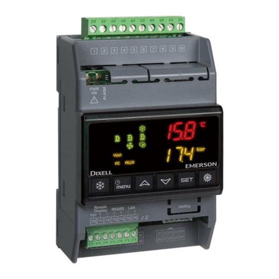
- Page 1 QUICK REFERENCE GUIDE IC100D EVO (rel. 1.0)
-
Page 3: Table Of Contents
INDEX GENERAL WARNING ....................5 PLEASE READ BEFORE USING THIS MANUAL ............5 SAFETY PRECAUTIONS ..................... 5 PRODUCT DISPOSAL (WEEE)..................... 6 USING THE QUICK REFERENCE GUIDE ..............6 ICHILL 105D / IC107D FEATURES ................7 USER INTERFACE ....................8 MEANING OF THE LEDS ...................... 8 DISPLAY AND ICONS ...................... - Page 4 17.4 ANALOG INPUT FOR PRESSURE TRANSDUCER PP30 (4 ÷ 20MA SIGNAL) ....28 17.5 ANALOG INPUT FOR PRESSURE RATIOMETRIC TRANSDUCER PPR30 (0 ÷ 5V SIGNAL) 17.6 PWM OUTPUT FOR CONDENSING FAN SPEED CONTROL ..........30 17.7 PROPORTIONAL OUTPUT FOR FAN CONDENSING CONTROL OR FOR COMPRESSOR INVERTER CONTROLLED OR FOR AUXILIARY OUTPUTS ............
-
Page 5: General Warning
GENERAL WARNING PLEASE READ BEFORE USING THIS MANUAL • This manual is part of the product and should be kept near the instrument for easy and quick reference. • The instrument shall not be used for purposes different from those described hereunder. It cannot be used as a safety device. -
Page 6: Product Disposal (Weee)
The connection to ground of the secondary coil of the transformer that supply the device ➢ may generate the malfunctionning of the device; where possible this connection must be avoided. PRODUCT DISPOSAL (WEEE) With reference to Directive 2002/96/EC of the European Parliament and of the Council of 27 January 2003 and to the relative national legislation, please note that: •... -
Page 7: Ichill 105D / Ic107D Features
ICHILL 105D / IC107D FEATURES FEATURES IC105D IC107D RELAYS DIGITAL INPUTS 9 (free voltage) configurable configurable PROBES 4 (NTC or PTC or Digital Input) configurable configurable 3 (NTC or PTC or 0..5V or 4..20mA or Digital Input) configurable configurable PROPORTIONAL OUTPUTS 2 (0÷10V or 4..20mA or PWM outputs) -
Page 8: User Interface
USER INTERFACE MEANING OF THE LEDS DISPLAY AND ICONS ICON MEANING / FUNCTIONNING °C °F Lighted when the display shows a temperature or pressure Lighted when the bottom display shows the clock Lighted during the programming parameters if it is time based Lighted in function menu when the display shows the defrost delay Alarm: blinking in case of alarm Lighted when sanitary hot water function is active... - Page 9 Lighted if anti freeze heaters/ integration heating / boiler are activated Flow switch alarm / supply fan overload (air / air unit) Water pump: lighted if at least one pump is ON Condenser fan: lighted if at least one fan is ON Lighted when a compressor is ON Blinking = when the delay of activation is running Lighted when auxiliary function is active...
-
Page 10: Display Layout
DISPLAY LAYOUT Pressing Up or Down button the display shows the temperature or pressure of the main probes configured in the instrument. The lower display shows the label of the selected probe while the upper display shows its value. OTHER DISPLAY INFORMATION READ THE SET POINT VALUE Press and release the SET key: If the unit is on standby:... -
Page 11: Modify The Set Point
MODIFY THE SET POINT • push SET key for at least 3 seconds • use the UP or DOWN key to modify the setpoint. In chiller mode it is possible to modify the chiller set point, in heat pump it is possible to modify the heat pump set point, in std-by it is possible to modify both the set point. -
Page 12: Key Combinantion
Pushing once during To exit from a group of parameters programming KEY COMBINANTION ACTION FUNCTION Push for 3 seconds together Enter the programming parameters Only in Pr3 level: push SET and Select the parameter level visibility Pr1 / Pr2 / Pr3 DOWN key Push once together Exit the programming parameters... -
Page 13: Parameters Programming With The "Hot Key 64
PARAMETERS PROGRAMMING WITH THE “HOT KEY 64” HOW TO PROGRAM THE INSTRUMENT WITH AN ALREADY PROGRAMMED “HOT KEY” (DOWNLOAD) Power off the instrument Insert the hot key already programmed (by software Wizmate or other instrument) Power on the instrument Automatically the parameters are downloaded During the download the regulation is locked and the top display shows the “doL”... -
Page 14: Enter Parameters Programming Level Pr1
10.1 ENTER PARAMETERS PROGRAMMING LEVEL PR1 Enter the Pr1 “User level”: Push SET + DOWN keys together for 3 seconds. The top display shows “PAS” and the bottom display shows “Pr1”. Push SET key and the top display shows “0” blinking Push UP or DOWN to select Pr1 password Push SET and, if the value is correct, the top display shows the first family of parameters “ALL”... -
Page 15: Menu ( Menu Key)
10. Push SET to confirm the new value 11. If necessary, modify others parameter 12. Push SET + UP keys together to exit parameters programming MENU ( MENU KEY) Enter the menu: • press the menu button; • press the UP or DOWN button to select the submenu; •... -
Page 16: Alarm Log List
To exit the ALrM reset, push MENU or wait the timeout. 11.2 ALARM LOG LIST ALOG FUNCTION Push MENU key Push UP or DOWN to select ALOG Push SET key The bottom display shows the alarm label, the top display shows a number in the range 00 to 99. Use the UP or DOWN keys to scroll the list. -
Page 17: Remote Lcd Panel Vgi810 Or V2I810
REMOTE LCD PANEL VGI810 OR V2I810 Two models of remote LCD panel are available; • VGI810 Visograph 1 series • V2I810 Visograph II seres The description of the user interface is available in the user manual of the Visograph. REMOTE TOUCH PANEL VTIC10 The description of the user interface is available in the user manual of the Visotouch. -
Page 18: Table Of The Output Status In Alarm Condition
TABLE OF THE OUTPUT STATUS IN ALARM CONDITION 15.1 M ACHINE ALARMS Alarm Alarm Comp. Heaters Support Evaporator Condenser Domestic Solar Condenser Auxiliary Code description heaters Pump / Pump hot water panel relay (air/air Supply fan Water Water unit) pump pump ACF1 Configuration... - Page 19 IEV Electronic APU1 Expansion Valve probe APU4 alarm Serial communication ASLA failure with I/O expansion Domestic hot AtAS water pump overload Condenser 1 AtC1 water pump overload alarm Condenser 2 AtC2 water pump overload alarm Evaporator 1 AtE1 water pump (boiler) overload alarm Evaporator 2...
-
Page 20: Circuit Alarm
(5) = Boiler heaters off if the water pump is the only configured water pump; if 2 water pumps are configured, the compressors are OFF if both water pumps are in alarm or not available (6) Compressors switched off if only production of domestic hot water is ongoing (7) In case of electronic expansion valve alarm all loads are OFF (8) This loads are not influenced directly by the alarm;... -
Page 21: Compressor Alarm
15.3 OMPRESSOR LARM Alarm Alarm description Compressor Compressors not involved Code Compressor (n) disabled (by dedicated procedure C(n)dS in menu function) C(n)dt Compressor (n) high discharge temperature C(n)HP Compressor(n) high pressure switch Compressor(n) oil pressure switch / Oil level C(n)oP switch C1Pd Compressor oil differential... -
Page 22: Wiring Connections
WIRING CONNECTIONS IC105D MODEL: HARDWARE RESOURCES 17.1 • 5 x digital outputs (relays): max. current on the relay contacts relè 5(2)A 250V max. common current 10A 250V • 9 x digital inputs free of voltage • 8 x analogue inputs: •... -
Page 23: Ic107D Model: Hardware Resources
IC107D MODEL: HARDWARE RESOURCES 17.2 • 7 x digital outputs (relays): max. current on the relay contacts relè 5(2)A 250V max. common current 10A 250V • 9 x digital inputs free of voltage • 8 x analogue inputs: • 5 x NTC preobe / PTC probe / digital input •... - Page 24 • 1 x TTL output for “HotKey 64” (for parameters programming) or for XJ485CX (interface module for monitoring system) • 1 x RS485 output to connect the device to a RS485 network (monitoring system) or XWEB system. max. current of relay contacts 5(2)A 250V max.
-
Page 25: Remote Panel Connection (Vi613 Evo Or V2I810 Or Vtic10)
17.1 REMOTE PANEL CONNECTION (VI613 EVO OR V2I810 OR VTIC10) It is possible to connect to the instrument up to two remote panels VI613 available with or without temperature sensor on board, or a V2I810 LCD panel, or a touch panel VTIC10; the use of keyboards VI613 exclude the possibility of using the keyboard Visograph or Visotouch and vice versa. - Page 26 VGI810 or V2I810 LCD PANEL 1592022020 Quick reference guide iCHILL 100DEVO rel. 1.0 26/40...
-
Page 27: Analog Inputs Ntc - Ptc Probes
VTIC10 TOUCH PANEL NTC – PTC P 17.2 NALOG NPUTS ROBES PbC = common terminal Pb1…Pb6 = probe inputs 1592022020 Quick reference guide iCHILL 100DEVO rel. 1.0 27/40... -
Page 28: Digital Inputs
17.3 IGITAL NPUTS GND = common terminal ID1…ID11 = digital inputs 17.4 30 (4 ÷ 20 NALOG NPUT FOR RESSURE RANSDUCER SIGNAL 12V = power supply for pressure transducers Pb3 and Pb4 = pressure transducer inputs 1592022020 Quick reference guide iCHILL 100DEVO rel. 1.0 28/40... - Page 29 17.5 30 (0 NALOG NPUT FOR RESSURE ATIOMETRIC RANSDUCER ÷ 5V SIGNAL +5V = power supply for pressure transducers GND = ground for pressure transducers Pb3 and Pb4 = pressure transducer inputs 1592022020 Quick reference guide iCHILL 100DEVO rel. 1.0 29/40...
-
Page 30: Pwm Output For Condensing Fan Speed Control
17.6 PWM O UTPUT FOR ONDENSING PEED ONTROL OUT2 and OUT3 = signals for the modulation of the condenser fan GND = ground for pressure transducers The compatible modules are the following: XV05PK mono-phase 500 Watt (2A) XV10PK mono-phase 1000 Watt (4A) XV22PK mono-phase 2200 Watt (9A) 1592022020 Quick reference guide iCHILL 100DEVO rel. -
Page 31: Proportional Output For Fan Condensing Control Or For Compressor Inverter Controlled Or For Auxiliary Outputs
17.7 ROPORTIONAL UTPUT ONDENSING ONTROL OR OMPRESSOR NVERTER ONTROLLED OR UXILIARY UTPUTS OUT1…OUT3 = signals for the modulation of the condenser fan GND = ground for pressure transducers 1592022020 Quick reference guide iCHILL 100DEVO rel. 1.0 31/40... -
Page 32: Proportional Output 0
17.8 0..10 PROPORTIONAL OUTPUT V TO CONTROL DUMPER MOTORS OUT1…OUT4 = signals for the modulation of the dumper motor GND = ground If the dumper motor has a common line between a pole of the power supply and the “–“ pole of the 0..10V signal, it is necessary to use two transformers for the power supply of the controller Ichill and the power supply of the dumper motor. - Page 33 1592022020 Quick reference guide iCHILL 100DEVO rel. 1.0 33/40...
-
Page 34: Proportional Outputs Configured For Aux Relay Control
17.9 ROPORTIONAL OUTPUTS CONFIGURED FOR AUX RELAY CONTROL OUT1…OUT4 = signals for relays GND = ground 1592022020 Quick reference guide iCHILL 100DEVO rel. 1.0 34/40... - Page 35 17.10 C IEV22D IEV12D E ONNECTION LECTRONIC XPANSION ALVE RIVER 1592022020 Quick reference guide iCHILL 100DEVO rel. 1.0 35/40...
-
Page 36: Installing And Mounting
INSTALLING AND MOUNTING 18.1 MECHANICAL CHARACTERISTIC Mount: DIN rail (EN 50022, DIN 43880) Material: PC-ABS Thermoplastic Self-extinguishing: V0 (UL94) Comparative Tracking Index (CTI): 300V Colour: Black IP protection IP10 1592022020 Quick reference guide iCHILL 100DEVO rel. 1.0 36/40... -
Page 37: Vertical Boards Vi613 Panel Cut-Out
18.2 VERTICAL BOARDS VI613 PANEL CUT-OUT The keyboard must be mounted on vertical panel with cut-out 72x56 mm, and screwed with two screws. The IP65 can be reached with the gasket RGW-V (optional). WALL MOUNTING: use the vertical V-KIT (black, white and grey) as described in the following scheme: 1592022020 Quick reference guide iCHILL 100DEVO rel. -
Page 38: Electrical Connections
ELECTRICAL CONNECTIONS The instrument is provided with: • 2 removable terminal blocks MOLEX MICROFIT 18 and 10 ways for power supply voltage / digital and analogue inputs and modulating outputs • 1 removable terminal blocks STELVIO 6 ways for the remote keyboard connections, RS485 and LAN •... -
Page 39: Analogue Inputs
20.2 A NALOGUE INPUTS Number of inputs: 5 (NTC, PTC, D.I.) 3 (NTC, PTC, 4..20mA, 0..5V, D.I.) Type of analogue input: NTC (-50T110°C; 10KΩ±1% a 25°C) (configurable via software parameter) PTC (-50T150°C; 990Ω±1% a 25°C) Rathiometric: 0.5..4.5V Current: 4..20mA Digital input (free contact) Operation range: -50°C ÷... -
Page 40: Digital Outputs
20.5 D IGITAL OUTPUTS Type: Relays with NO contacts Number of outputs: 5: IC105D model 7: IC107D model Maximum load: 5A(250Vac) SPST 5(2)A Note: Verify maximum current of the loads and maximum current of the common line of the relay (10A max). There is double insulation between the digital outputs and the low voltage of the rest of the circuit.