Advertisement
Quick Links
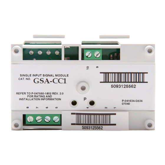
GSA-CC1 Single Input Signal Module
Installation Sheet
Description
The GSA-CC1 Single Input Signal Module is an addressable
module that is used to connect the following circuits:
•
Audible and visible notification appliance circuits
(synchronized or unsynchronized)
•
Speaker circuits
•
Two-way telephone communication circuits (three-state or
four-state)
Upon command from the loop controller, the module connects
supervised Class B signal or telephone circuits to the
respective riser input. The riser input can be 24 VDC (to
operate polarized audible and visible signal notification
appliances), 25 or 70 VRMS (to operate audio evacuation
speakers), or firefighter telephones.
The module does not provide signal synchronization. To meet
UL 864 requirements for horn and strobe signal
synchronization, you must install a Genesis Signal Master
module.
The GSA-CC1 module requires one address on the signaling
line circuit (SLC). Addresses are assigned electronically. There
are no address switches.
Diagnostic LEDs provide visible indication of the state of the
module through the cover plate:
•
Normal: Green LED flashes
•
Alarm/active: Red LED flashes
© 2017 United Technologies Corporation
Personality codes
The module requires the loop controller to download the
personality code that determines how the module operates.
Use the personality codes described below to configure the
GSA-CC1. See Table 1 for listing information.
Table 1: Personality code listing information
Code
Description
5
Signal - supervised
output (Class B)
6
Telephone - three-state
(Class B)
26
Telephone - four-state
(Class B)
Signal - supervised output (Class B).
Personality code 5:
Configures the GSA-CC1 module as a riser selector for audible
and visible notification appliance circuits or for
single-channel audio circuits. The output circuit is monitored for
open or shorted wiring. If a short exists, the module will not
activate in order to prevent shorting the riser. The module will
activate once the short is cleared.
6: Telephone - three-state (Class B)
Personality code
Configures the module as a riser selector for a three-state
firefighter telephone. When a telephone handset is plugged
into its jack or lifted from its hook, the module generates its
own ring-tone signal, making a separate ring-tone riser
unnecessary. The module sends this signal to the control panel
to indicate the presence of an off-hook condition, and waits for
the system operator to respond to the call. When the system
operator responds, the ring-tone signal is disabled.
Personality code 26:
Configures the module as a riser selector for a four-state
firefighter telephone. Operation is the same as Personality
code 6 except that the module can distinguish when a
telephone is off-hook and when the circuit is shorted, which
causes a trouble condition.
1 / 6
P/N P-047550-1802-EN • REV 05 • ISS 03FEB17
UL 864
Yes
No
Yes
Telephone - four-state (Class B).
CAN/ULC-
S527
Yes
No
Yes
Advertisement

Related Manuals for Kidde GSA-CC1


Summary of Contents for Kidde GSA-CC1
- Page 1 Signal - supervised output (Class B). Personality code 5: module that is used to connect the following circuits: Configures the GSA-CC1 module as a riser selector for audible • Audible and visible notification appliance circuits and visible notification appliance circuits or for (synchronized or unsynchronized) single-channel audio circuits.
-
Page 2: Installation
Each terminal on the module is limited to a single conductor. • Test resistors are supplied with the GSA-CC1 to prevent trouble signals on unused circuits during installation. When connecting field wires, remove the test resistors and install a UL/ULC Listed 47 kΩ EOLR at the end of the circuit. - Page 3 To wire the module: Verify that all field wiring is free of opens, shorts, and ground faults. Make all the connections as shown in Figure 3 through Figure 5. Figure 3: Wiring diagram for NAC (personality code 5) (1)(2)(3)(4) (10) (3)(8) (1) Signal polarity is shown when the circuit is in supervisory state.
- Page 4 Figure 4: Wiring diagram for audio (personality code 5) (1)(2)(3)(4) (10) (1) Signal polarity shown when the circuit is in supervisory state. (4) Unshielded twisted pair. Polarity reverses when the circuit is active. (5) 47 kΩ EOLR (P/N EOL-47). (2) Supervised. (6) Signaling line circuit (SLC) to next device.
- Page 5 NFPA 70 National Electrical Code for more details. (10) (4) Required if the distance from the GSA-CC1 to the phone is greater than 5 ft. Shield must be continuous, insulated, and isolated from ground, except for the connection to chassis (3)(8) ground in the control panel.
-
Page 6: Specifications
Specifications Regulatory information Operating voltage range 15.20 to 19.95 VDC FCC compliance This device complies with part 15 of the FCC Rules. Operation is subject to the following two Current conditions: (1) This device may not cause Standby 310 µA harmful interference, and (2) this device must Activated 135 µA...