Table of Contents
Advertisement
Quick Links
Advertisement
Table of Contents

Related Manuals for Jet HVBS-710G


Summary of Contents for Jet HVBS-710G
- Page 1 This .pdf document is bookmarked Operating Instructions and Parts Manual 7x10-inch Gear Head Mitering Band Saw Model HVBS-710SG 427 New Sanford Road LaVergne, Tennessee 37086 Part No. M-413452 Ph.: 800-274-6848 Revision C3 01/2021 www.jettools.com Copyright © 2016 JET...
-
Page 2: Warranty And Service
Accessories; Shop Tools; Warehouse & Dock products; Hand Tools; Air Tools NOTE: JET is a division of JPW Industries, Inc. References in this document to JET also apply to JPW Industries, Inc., or any of its successors in interest to the JET brand. -
Page 3: Table Of Contents
2.0 Table of Contents Section Page 1.0 Warranty and Service ............................. 2 2.0 Table of Contents ..............................3 3.0 Safety Warnings ..............................4 4.0 About this manual ..............................5 5.0 Features ................................. 6 6.0 Specifications ................................. 6 ... -
Page 4: Safety Warnings
19. Provide for adequate space surrounding work area and non-glare, overhead lighting. Do not use this band saw for other than its intended use. If used for other purposes, JET 20. Keep the floor around the machine clean and disclaims any real or implied warranty and free of scrap material, oil and grease. -
Page 5: About This Manual
Whatever accepted methods or materials are used, always make personal safety a priority. If there are questions or comments, please contact your local supplier or JET. JET can also be reached at our web site: www.jettools.com. -
Page 6: Features
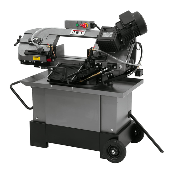
5.0 Features Figure 1 Blade tension handle 10. Adjustable work stop Cast iron bow 11. Steel stand with coolant tank Coolant taps 12. Chip guide plate Centralized control switch 13. Vise handwheel with quick release 3-speed gearbox 14. Cast iron table 1HP motor 15. - Page 7 The specifications in this manual were current at time of publication, but because of our policy of continuous improvement, JET reserves the right to change specifications at any time and without prior notice, without incurring obligations.
-
Page 8: Set-Up And Assembly
7.0 Set-Up and Assembly Tools required for assembly: 12mm wrench 3, 4, and 6mm hex keys 7.1 Unpacking and cleanup Inspect contents of shipping container for shipping damage. Report any damage to your distributor. Remove all contents from carton, and compare to the contents list in this manual. -
Page 9: Assembly
Figure 4 Use properly rated lifting equipment (hoist or 7.3 Assembly forklift) with straps placed beneath cast iron portion of saw. Refer to Figure 4. Position saw atop base and secure with four screws and washers (HP-1/6/7). Band should disconnected from electrical power during Install work stop assembly (A/B/C) into hole on assembly and setup. -
Page 10: Vertical Cutting Plate
7.4 Vertical cutting plate These steps are only necessary when using band saw in vertical position. Disconnect machine from power source. Open valve on hydraulic cylinder (lever parallel to cylinder) and raise bow to vertical position. Remove two screws and remove seat plate, as shown in Figure 5. -
Page 11: Coolant System
7.6 Coolant system Local codes take precedence over recom- mendations. Make sure there is coolant in 8.1 Grounding instructions the tank before operating, to prevent damage to pump. 1. All Grounded, Cord-connected Tools: Use of a water-soluble coolant will increase cutting In the event of a malfunction or breakdown, efficiency and prolong blade life. -
Page 12: Voltage Conversion
(#201 in parts list) with the 230V contactor (separate purchase; p/n HVBS710S- 250N. See your dealer or call JET to order.) The plug on the end of the motor cord must be replaced with a UL/CSA listed plug rated for Recommended 240V. -
Page 13: Adjustments
9.0 Adjustments The settings on your band saw, such as blade squareness and tracking, were carefully performed by the manufacturer. You should, however, verify these before operating, in case misalignment has occurred during shipping. 9.1 Squaring blade to table Disconnect machine from power source. Place machinist’s square (A, Figure 14) on table and against blade. -
Page 14: Miter Cuts
9.4 Miter cuts Loosen handle (G, Figure 17). Rotate bow to desired angle up to 45-degrees, using scale indicator on front of base. Tighten handle. Figure 18 9.6 Counterbalance spring The counterbalance spring helps control the amount of weight the saw bow puts on the workpiece when the hydraulic control valve is fully open. -
Page 15: Blade Tension
Raise bow to vertical position, and secure in 11. Close back cover and secure with knobs. place by turning off hydraulic cylinder. 12. Install red blade guard, and brush assembly. Remove red blade guard (A, Figure 19) by 13. Connect machine to power source. removing two screws. -
Page 16: Test Cutting To Verify Adjustment
Blade tracking has been tested at the factory. accurate, quieter cutting and longer machine Adjustment is rarely required when the blade is and blade life. used properly and if the blade is correctly welded. When the paper is cut, back off the set screw If a tracking problem occurs, first inspect blade slightly. -
Page 17: Setting Blade Speed
9.11 Setting blade speed turn freely with this clearance. If the clearance is incorrect, the blade may track off the drive wheel. Turn machine OFF. Disconnect machine from power source. Turn lever (Figure 23) to desired setting: Raise bow to vertical and secure in place by #1 –... -
Page 18: Limit Switch
To stop saw before it reaches the end of cut, push specific blades on specific materials. However, the Off button (B). The saw will automatically stop at following procedure will be adequate for break-in of the end of a cut. JET-supplied blades lower alloy ferrous materials. -
Page 19: Evaluating Cutting Efficiency
Place workpiece in vise and tighten vise. The If chips formed are curled, but colored — that is, workpiece should be fitted directly between the either blue or straw-colored from heat generated jaws without adding other objects. during the cut — then the feed rate is too high. When workpiece to be cut is a profiled section, If chips are slightly curled and are not colored by flat piece or special shape, refer to examples... -
Page 20: Coolant Level
12.1 Coolant level Reinstall drain plug and return bow to horizontal position. Maintain coolant level. Low coolant level can cause Remove vent plug (B), and fill gear box foaming and high blade temperatures. Replace through the hole with approximately 0.3L dirty coolant;... - Page 21 Trouble Probable Cause Remedy Cuts not square. Feed pressure too great. Decrease feed pressure. 90° angle stop is not set correctly. Adjust stop until blade is square with vise. Incorrect blade toothing in relation to Check Machinery’s Handbook for workpiece. recommended blade type.
-
Page 22: Replacement Parts
Number of your machine available when you call will allow us to serve you quickly and accurately. Non-proprietary parts, such as fasteners, can be found at local hardware stores, or may be ordered from JET. Some parts are shown for reference only, and may not be available individually. -
Page 23: Hvbs-710Sg Table And Stand Assembly - Exploded View
14.1.1 HVBS-710SG Table and Stand Assembly – Exploded View... -
Page 24: Hvbs-710Sg Bow Assembly - Exploded View
14.1.2 HVBS-710SG Bow Assembly – Exploded View... -
Page 25: Hvbs-710Sg Assembly - Parts List
14.1.3 HVBS-710SG Assembly – Parts List Index No. Part No. Description Size 1 ....HVBS710S-1G ....Bottom Pan ....................1 1-1 ..... TS-0060071 ....Hex Cap Screw ........... 3/8" x 1-1/2" ....2 1-2 .... TS-0570031 ....Hex Nut ............... 3/8" ........ 2 1-3 ..... - Page 26 Index No. Part No. Description Size 57 ....TS-0720081 ....Spring Washer ............ 5/16" ......2 59 ....TS-2311181 ....Hex Nut ............... M18 x 2.5 ...... 2 60 ....HVBS710S-60 ....Washer ..................... 2 61 ....HVBS710S-61 ....Bushing ............... Ø25 x 34 x 10mm ..1 ....
- Page 27 Index No. Part No. Description Size 121 .... HVBS710S-121 ....Floating Vise Jaw ..................1 122 .... TS-0570031 ....Hex Nut ............... 3/8" ........ 2 123 .... TS-0060031 ....Hex Cap Screw ........... 3/8" x 3/4"...... 1 124 .... HVBS710S-124 ....Spring Bracket ..................1 125 ....
- Page 28 210 .... HVBS710S-LBDA ..Label – Blade Direction Arrow (not shown) ..........1 211 .... HVBS710SG-ID ..... I.D. Label (not shown) ................1 ....HVBS710S-HP ....Hardware Package (see contents page 8) ..........1 ....JET-92 ......JET Logo ............92 x 38mm ....1...
-
Page 29: Hvbs-710Sg Gearbox Assembly - Exploded View
14.2.1 HVBS-710SG Gearbox Assembly – Exploded View... -
Page 30: Hvbs-710Sg Gearbox Assembly - Parts List
14.2.2 HVBS-710SG Gearbox Assembly – Parts List Index No. Part No. Description Size ....HVBS710SG-196-1N Gearbox Assembly (index #1 thru 42) (serial #150600355 and higher) .... 1 1 ....HVBS710SG-129 ..Vent Plug ....................... 1 2 ....TS-1504061 ....Hex Socket Head Cap Screw ......... M8x30 ......5 3N ..... -
Page 31: Electrical Connections For Hvbs-710Sg
15.0 Electrical Connections for HVBS-710SG... - Page 32 427 New Sanford Road LaVergne, Tennessee 37086 Phone: 800-274-6848 www.jettools.com...