
Related Manuals for Majestic fireplaces SHR36


Summary of Contents for Majestic fireplaces SHR36
- Page 1 1384 Underwriter's Laboratories Report No. MH6018 SHR cover 5/27/99 djt DO NOT DISCARD THIS MANUAL: Retain for future use. SHR Series Woodburning Fireplace Homeowner's Installation and Operating Manual For Models: SHR36 SHR42A SHR48 SHR52 20001384 4/07 Rev. 19...
-
Page 2: Table Of Contents
Majestic Fire- places dealer. Only use CFM Corporation components or the warranty will be voided and a fire hazard may be created. CFM Corporation warranty will be voided by and CFM Corporation disclaims any responsibility for the follow- ing actions: •... -
Page 3: Specifications And Framing
SHR36 Series Woodburning Fireplace 57�����" (1472mm) ���" ���" Outside 13���" (349mm) 7���" (197mm) (368mm) Fig. 1 SHR36 Series specifications and framing. SHR42A Series Woodburning Fireplace 65���" (1654mm) ���" ���" 19���" Outside (489mm) 14���" (362mm) 9" (229mm) 10����" (258mm) Fig. 2 SHR42A Series specifications and framing. - Page 4 SHR48 Series Woodburning Fireplace 66���" (1686mm) ���" ���" Outside 13���" 7���" (349mm) (197mm) Fig. 3 SHR48 Series specifications and framing. SHR52 Series Woodburning Fireplace 74���" (1886mm) ���" ���" Outside 13���" 9���" (343mm) (235mm) Fig. 4 SHR52 Series specifications and framing. ���"...
-
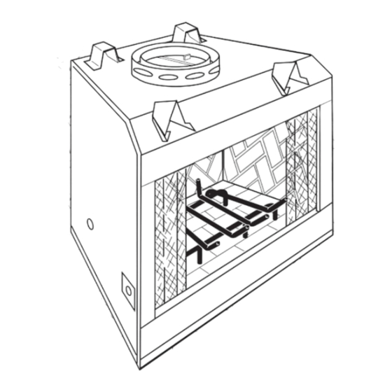
Page 5: Parts Identification
(cut out around firestop) Firestop Ceiling Level Gas Line Access (both sides) Outside Air Cover Plate Fig. 5 Fireplace and chase parts identification. (SHR48 shown) 20001384 SHR36 SHR42A SHR48 SHR52 FP1531 FP554A SH Series 1/28/99 SHR Series Woodburning Fireplaces Front Width Back Width 35³⁄₄"... -
Page 6: Chimney Requirements
Illustration Key The following safety rules apply to offset installations (letters correspond with illustra- tion above): A. Height of the chimney is measured from the hearth to the chimney exit. SHR36 SHR42A SHR48 SHR52 Max.: Min.: 0 Elbows 14'6" 14'6"... -
Page 7: Planning Information
Preplanning an installation is very important to ensure safety and to save time and money. An installer must predetermine where a fireplace will be set and how the chimney system will be run. Mounting the Fireplace A fireplace may only be mounted on the following sur- faces: 1. -
Page 8: Installation
Chimney Supports The chimney system is supported by the fireplace for vertical chimney heights less than 30 feet above the hearth. Chimney supports are required if the vertical height exceeds 30 feet with 11CF chimneys. Locate chimney supports at ceiling holes or other structural framing at 30 foot heights. - Page 9 Fig. 10 Insulating between platform and fireplace. Framing Framing can be constructed before or after the fireplace is set in place, however, most installers build the frame before setting the fireplace. Frame fireplace with 2 x 4 lumber or heavier materials. Refer to framing dimensions in Figures 1 - 4 for basic fireplace specifications.
- Page 10 Offset Installation In order to clear an obstruction, it may be necessary to offset chimney from vertical. This is accomplished by using CFM Corporation elbows. Use the 30˚ Offset Elbow table on Page 6 to determine proper offset and parts required.
- Page 11 The inside dimension of the frame must be the same as the hole size selected from Figure 11 in order to provide the required 2 inches of air space between the outside diameter of the chimney and the edges of the framed ceiling hole.
- Page 12 Open Closed Fig. 18 Outside air operation. Installing the Chimney System Start by attaching the first chimney section to the collar on top of the fireplace. FP710a Install the pipe as pictured in Figure 19. When you SHR OUTSIDE AIR LEVER WOOD FIREPLACES get a good lock, you will hear the pipe clearly snap 10/21/99...
- Page 13 Attic Installation Nails (4) Firestop Spacer Flange Down Into Hole NOTE: If the attic insulation shield is used, the firestop is not required in the attic installation. Fig. 21 Installing firestop spacer. Canadian Requirements for Insulation Shield In Canada, an attic insulation shield is required to prevent attic insulation from contacting the chimney section.
- Page 14 Cut and Frame Roof Hole Size of roof hole varies with the type of chimney termi- nation installed. Refer to installation instructions pro- vided with the chimney termination to find correct size roof hole. There must be a 2" (51 mm) air space between out- ermost portion of chimney sections and any adjacent combustible surfaces.
- Page 15 Mantel Clearance - No Noncombustible Facing Material (305mm) Combustible Mantel and Trim Max. 12" (305mm) min. * Minimum width from top of surround to bottom of screen rail Ledge Bracket Fig. 24 Mantel clearance. Framing Shield Fig. 25 SHR52 framing shield may be used to attach finish material.
- Page 16 Finished Wall Noncombustible Decorative Fac- Must be Sealed with Noncombustible Material Surround Fig. 27 Facing on fireplace surround flush with finished wall. FP1167 facing flush with finished wall 12/20/01 djt 1���" Ref. * 12" from top of fireplace opening. ** 6" from top of fireplace opening. (Noncom- bustible material must separate the black face surround of the fireplace and any combustible mantel material)
- Page 17 SP40. Rt must =1.85 minimum. Examples of wall shield insulation: 1. Manville - CERAFORM 126, K=.27, 1/2 inches thick 2. CFM Corporation - EH2416, K = .458, 1 inch thick required. 40" Min. Noncombustible Insula-...
- Page 18 Combustible material permitted within shaded area. * Noncombustible wall shield requires 1" CFM Corporation EH2416 insulation (minimum R Value = 1.85) between decorative noncombustible rigid covering and combustible wall. Minimum height and width is 40" x 40".
- Page 19 Majestic Safety Strips Must be Overlapped 1/2" Min. Fig. 35 Sealing detail. Installing Line for Gas Logs CFM Corporation fireplaces are designed to accept a 1/2 FP1172 inch gas line for installation of an approved gas appli- sealing detail 2 ance.
-
Page 20: Replacement Parts
CFM Corporation reserves the right to make changes in design, materials, specifications, prices and discontinue colors and products at any time, without notice. SHR36/42A/48/52 Woodburning Fireplace For units FH30R0, GH40R0, HH30R0, IH10R0 Ref. Description 1. Damper Weld Assembly 2. Damper Handle 3. -
Page 21: Accessories
CFM Corporation approved components. If you use an unapproved component to make any modifications, you may create a possible fire hazard and will void the CFM Corporation warranty. In addi- tion, such action may void the coverage provided by the owner’s insurance. - Page 22 Used to terminate chimney at the top of a chase. Adapter kit is included, flashing is not included. For use with CFM Corporation Type "11CF" Chimney Systems. Used to terminate chimney on the roof. Flashing not included.
- Page 23 CFM Corporation, at its option, if replacement parts are available, will provide a replacement for any defec- tive part at a cost to the consumer of CFM Corporation then current list price, FOB CFM Corporation factory. D. Liners (Refractory or Metal): 1.
- Page 24 CFM Corporation 410 Admiral Blvd. • Mississauga, Ontario, Canada L5T 2N6 800-668-5323 • www.cfmcorp.com © CFM Corporation...