
Related Manuals for Planet GS-6320 Series


Summary of Contents for Planet GS-6320 Series
- Page 1 L3 Multiple Gigabit + 2-/4-Port 10G SFP+ Managed Switch GS-6320 LCD Switch Series Quick Installation Guide...
-
Page 2: Table Of Contents
Table of Contents 1. Package Contents ..................3 2. Requirements ..................... 4 3. Terminal Setup ................... 5 3.1 Logging on to Console ................. 6 3.2 Configuring IP Address ................. 6 4. Starting Web Management ................9 4.1 Logging in to the Managed PoE Switch ..........9 4.2 Saving Configuration via Web ..............11 5. Recovering Back to Default Configuration .............13 6. -
Page 3: Package Contents
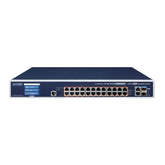
1. Package Contents Thank you for purchasing PLANET L3 Multiple Gigabit + 2-/4-Port 10G SFP+ Managed Switch with LCD. The description of this model is shown below: PoE Power Model Name PoE Ports 10G SFP+ 10G RJ45 Budget Input GS-6320-24UP2T2XV 24-Port 802.3bt 600W AC/DC “Managed PoE Switch” is used as an alternative name in this Quick Installation Guide. -
Page 4: Requirements
2. Requirements z Workstations running Windows 10/XP/2003/Vista/7/8/2008, MAC OS X or later, Linux, UNIX, or other platforms are compatible with TCP/IP protocols. z Workstations are installed with Ethernet NIC (Network Interface Card) z Serial Port Connection (Terminal) The above Workstations come with COM Port (DB9) or USB-to-RS232 converter. The above Workstations have been installed with terminal emulator, such as Hyper Terminal included in Windows XP/2003. -
Page 5: Terminal Setup
3. Terminal Setup To configure the system, connect a serial cable to a COM port on a PC or notebook computer and to RJ45 type of serial port of the Managed PoE Switch. PC / Workstation with Terminal Emulation Software Managed Switch RS232 to RJ45 Cable Serial Port RJ45 Console Port Figure 3-1: Managed PoE Switch Console Connectivity A terminal program is required to make the software connection to the Managed PoE Switch. -
Page 6: Logging On To Console
3.1 Logging on to Console Once the terminal is connected to the device, power on the Managed PoE Switch, and the terminal will display “running testing procedures”. Then, the following message asks to log in user name and password. The factory default user name and password are shown as follows and the login screen in Figure 3-3 appears. - Page 7 To check the current IP address or modify a new IP address for the Switch, please use the procedures as follows: Show the current IP Address 1. At the “#” prompt, enter “show ip interface brief”. 2. The screen displays the current IP address as shown in Figure 3-4. Figure 3-4: IP Information Screen Configuring IP Address 3. At the “#” prompt, enter the following command and press <Enter> as shown in Figure 3-5.
- Page 8 Store current switch configuration 5. At the “#” prompt, enter the following command and press <Enter>. # copy running-config startup-config Figure 3-6: Saving Current Configuration Command Screen If the IP is successfully configured, the Managed PoE Switch will apply the new IP address setting immediately. You can access the Web interface of the Managed PoE Switch through the new IP address. If you are not familiar with the console command or the related parameter, enter “help”...
-
Page 9: Starting Web Management
4. Starting Web Management The following shows how to start up the Web Management of the Managed PoE Switch. Note the Managed PoE Switch is configured through an Ethernet connection. Please make sure the manager PC must be set to the same IP subnet address. - Page 10 3. After entering the password, the main screen appears as Figure 4-3 shows. Figure 4-3: Web Main Screen of Managed PoE Switch 4. The Switch Menu on the left of the Web page lets you access all the commands and statistics the Managed PoE Switch provides. Figure 4-4: Switch Menu Now, you can use the Web management interface to continue the Switch management.
-
Page 11: Saving Configuration Via Web
4.2 Saving Configuration via Web To save all applied changes and set the current configuration as a startup configuration, the startup-configuration file will be loaded automatically across a system reboot. 1. Click Maintenance > Open Switch Maintenance on the left page > Press Save Startup Config. - Page 12 2. Or you can press the “Save Configuration” button. 3. Press the “Save Configuration” button to save.
-
Page 13: Recovering Back To Default Configuration
5. Recovering Back to Default Configuration IP address has been changed or admin password has been forgotten – To reset the IP address to the default IP address “192.168.0.100” or reset the login password to default value, press the hardware-based reset button on the rear panel for about 10 seconds. After the device is rebooted, you can log in the management Web interface within the same subnet of 192.168.0.xx. -
Page 14: Lcd Touch Screen
6. LCD Touch Screen The Managed PoE Switch has a 2.4-inch color LCD touch screen with management functions. Tap the LCD touch screen to wake the LCD touch screen. Figure 6-1: Waking the LCD Touch Screen The factory default LCD configurations are shown as follows. Default LCD: Enable Default Touch Screen: Enable Default Backlight Timeout: Enable Default Backlight Timeout Time: 300 Default Read Only Mode: Disable Default Screen: Main Menu Default Time Interval: 10 Default Color Scheme: Dark Default Pin Number: 1234... - Page 15 You can use the Web management interface and click LCD, and then LCD Management to change the LCD configuration. Please refer to the user’s manual for more.
-
Page 16: Customer Support
7. Customer Support Thank you for purchasing PLANET products. You can browse our online FAQ resource and User’s Manual on PLANET Web site first to check if it could solve your issue. If you need more support information, please contact PLANET switch support team. PLANET online FAQs: http://www.planet.com.tw/en/support/faq.php?type=1 Switch support team mail address: support@planet.com.tw GS-6320 LCD Series User’s Manual: https://www.planet.com.tw/en/support/downloads?method=category&c1=lan- switches&p=&type=3 (Please select your switch model name from the drop-down menu of Product Model.) Copyright © PLANET Technology Corp. 2019.