Table of Contents
Advertisement
Quick Links
Advertisement
Table of Contents

Related Manuals for Oki C650/ES6450


Summary of Contents for Oki C650/ES6450
- Page 1 C650/ES6450 Basic Operation Guide...
-
Page 2: Table Of Contents
Table of Contents Table of Contents Loading paper ..........70 1. Getting started ........4 Procedure for loading paper ......70 Applicable paper ..........70 Safety precautions ..........5 Inapplicable paper ..........72 General cautions ..........6 Paper precautions by type ......... 72 Preface .............. - Page 3 Table of Contents 6. Management of this machine ..113 Admin password ..........114 Checking the factory default admin passwords 114 Inputting the factory default admin passwords 116 Changing the admin password ......117 7. Maintenance ........119 Precautions for replacing consumables ..120 Service life and replacement cycle of consumables ..........
-
Page 4: Getting Started
Getting started Getting started Safety precautions ..................5 General cautions ..................6 Preface ....................... 8 Trademarks ....................9 About this manual ..................10 Features of this machine ................12 - 4 -... -
Page 5: Safety Precautions
Getting started Safety precautions Read this manual for your safety before using the product. Mishandling due to ignoring this display may cause death or serious injury. Mishandling due to ignoring this display may cause personal injury. - 5 -... -
Page 6: General Cautions
Getting started General cautions Do not touch the safety switch inside the machine. Doing so may cause electric shock when high voltage occurs. In addition, gears can rotate, which may result in personal injury. Do not use an inflammable spray near the machine. Doing so may cause a fire since there is an area heating up within the machine. - Page 7 Getting started Do not approach the paper discharger when the power is on or during printing. Doing so may cause injury. Do not touch a broken display. Doing so may cause injury. If any liquid (liquid crystal) leaking from the display gets into the eyes or mouth, wash it off promptly with a large quantity of water.
-
Page 8: Preface
Getting started Preface • EMERGENCY FIRST AID Take care with toner powder: If swallowed, give small amounts of cold water and seek medical attention. DO NOT attempt to induce vomiting. If inhaled, move the person to an open area for fresh air. Seek medical attention. If it gets into the eyes, flush with large amounts of water for at least 15 minutes keeping eyelids open. -
Page 9: Trademarks
10.0 The simplified EU declaration of conformity Hereby, Oki Electric Industry Co., Ltd. declares that the radio equipment type "AW-CM382" is in compliance with Directive 2014/53/EU. The full text of the EU declaration of conformity is available at the following internet address: https://www.oki.com/eu/printing/support/declaration-of-conformity... -
Page 10: About This Manual
Copyrights All rights belong to Oki Electric Industry Co., Ltd. This manual may not be reproduced, transcribed or translated without permission. Be sure to obtain the written approval from Oki Electric Industry Co., Ltd. - Page 11 Getting started About symbols This section describes the symbols used in this manual and their meanings. Symbol Meaning « » Indicates buttons/keys on the operator panel of this machine. Indicates keys on the PC keyboard. Indicates menu names, item names, options, etc. displayed on the display. Indicates menus, windows and dialog box names displayed on the PC screen.
-
Page 12: Features Of This Machine
Getting started Features of this machine Installable in restrained space As the machine is compact, the space between both sides of this machine and the wall can be as small as 20 mm. (When the optional caster stand is not installed) ... -
Page 13: Connecting To The Pc After Preparing This Machine
Connecting to the PC after preparing this machine Connecting to the PC after preparing this machine Installation ....................14 Unpacking ....................16 Checking accessories ................18 Installing the starter toner cartridge ............19 Installing options ..................20 Connecting the power cord ..............31 Loading paper in the tray ................. -
Page 14: Installation
Connecting to the PC after preparing this machine Installation Installation environment Install this machine in the following environment. Ambient temperature: 10°C to 32°C Ambient humidity: 20% to 80% RH (relative humidity) Maximum wet-bulb temperature: 25°C Make sure there is no condensation. Failure to do so may cause a malfunction. ... - Page 15 Connecting to the PC after preparing this machine Side view (When the rear output tray is used) Depending on the installation environment, the temperature inside this machine may rise and the printing speed may slow down. Side view (When the rear output tray is closed and a cable with angled connector is used) Depending on the installation environment, the temperature inside this machine may rise and the printing speed may slow down.
-
Page 16: Unpacking
Connecting to the PC after preparing this machine Unpacking Doing so may cause injury. This machine weighs approx. 30 kg, so be sure to have it lifted by at least 2 personals. Be sure to use the consumables/maintenance items supplied with this machine first. If you install the consumables/maintenance items other than those supplied first, the lifespan may not be displayed correctly or the accessories may not be usable later. - Page 17 Connecting to the PC after preparing this machine Lift this machine and place it at the installation site. Remove the drying agent on the top of this machine. To use the optional expansion tray, see "Installing options(P.20)". - 17 -...
-
Page 18: Checking Accessories
Connecting to the PC after preparing this machine Checking accessories Make sure that you have all the following accessories. Doing so may cause injury. This machine weighs approx. 30 kg, so be sure to have it lifted by at least 2 personals. ... -
Page 19: Installing The Starter Toner Cartridge
Connecting to the PC after preparing this machine Installing the starter toner cartridge When you use this machine for the first time, install the included starter toner cartridge. If an optional toner cartridge is installed and used first, you may not be able to use the starter cartridge later. ... -
Page 20: Installing Options
Connecting to the PC after preparing this machine Installing options This section explains the installation of options. If no option is installed, proceed to " Connecting the power (P.31)". cord The following options are available. Be sure to turn off the power and unplug the power cord and cables before installing any options. If an option is installed with the power on, the main unit and the option may be damaged. - Page 21 Connecting to the PC after preparing this machine Ethernet and wireless LAN can be used simultaneously on different networks. Model: 45830222 Turn off this machine and unplug the power cord. If you install it with the power on, the main unit or wireless LAN module may be damaged. Turning the power off(P.69) Open the wireless LAN module cover on the side of this machine.
-
Page 22: Installing The Expansion Tray Unit
Connecting to the PC after preparing this machine Input the admin password using the numeric keypad, and press «OK». Admin password(P.114) Check that [Network Setup] is selected, and press «OK». Check that [General Setup] is selected, and press «OK». Check that [Extended Network] is selected, and press «OK». Press ▼to select [Wireless], and press «OK». - Page 23 Connecting to the PC after preparing this machine Install the expansion tray unit to increase the quantity of paper that can be loaded. After installation, set the number of trays in the printer driver. Up to three extension trays can be installed. Be sure to install the attached fixing parts. To install any of the three expansion trays, it is recommended to install the optional dedicated caster stand to avoid the risk of tipping.
- Page 24 Connecting to the PC after preparing this machine Fix the stacked expansion trays on both sides with accessories by using a flat-head screwdriver. With the main unit and the expansion trays aligned on the right side and front, gently stack them so that the protrusions of the expansion tray fit into the holes on the bottom of the main unit.
-
Page 25: Installing The Dedicated Caster Stand
Connecting to the PC after preparing this machine Do not press on the back of this machine or the image drum basket when the output tray is open and the image drum is pulled out. Do not press on the cassette from above when the cassette is pulled out. ... - Page 26 Connecting to the PC after preparing this machine It also comes with anti-tip feet to avoid the risk of tipping. It is recommended to use it when the expansion tray is installed. A Phillips-head screwdriver and a flat-head screwdriver are required to install the caster stand. ...
- Page 27 Connecting to the PC after preparing this machine Then, mount the anti-tip foot b (x 3) to both sides and the back. Check that the anti-tip foot a and the anti-tip foot b (x 3) are inserted in place by turning the dedicated caster stand upside down.
- Page 28 Connecting to the PC after preparing this machine With the main unit or the expansion tray aligned with the dedicated caster caster on the right side and the front, gently stack them so that the positioning pins of the dedicated caster stand fit into the holes on the bottom.
- Page 29 Connecting to the PC after preparing this machine Fix the stacked expansion trays on both sides with accessories by using a flat-head screwdriver. When multiple expansion trays are installed, with the main unit and the expansion trays aligned on the right side and front, gently stack them so that the protrusions of the expansion tray fit into the holes on the bottom of the main unit.
- Page 30 Connecting to the PC after preparing this machine Before moving this machine, unlock the casters (2 places). After moving this machine, lock the casters (2 places) to prevent accidental sliding. When transporting this machine, replacing consumables or maintenance parts, or loading paper in the tray, check the following points to avoid the risk of tipping.
-
Page 31: Connecting The Power Cord
Connecting to the PC after preparing this machine Connecting the power cord About the power supply The power supply must meet the following requirements. Voltage: 110 to 127V AC (Range 99 to 140V AC) / 220 to 240V AC (Range 198 to 264V AC) Power supply frequency: 50/60 Hz ±... -
Page 32: Loading Paper In The Tray
Connecting to the PC after preparing this machine Loading paper in the tray This section describes the procedure assuming that A4-sized plain paper is loaded in Tray 1. When other paper is loaded, see " (P.70)". Loading paper Pull out the paper cassette. Slide the paper guide and the blue part of the paper stopper to fit the size of the paper to be loaded. - Page 33 Connecting to the PC after preparing this machine Return the paper cassette to this machine. Set the size, type and weight of the paper on the operator panel. Loading paper(P.70) - 33 -...
-
Page 34: Connecting Via A Wired Lan
Connecting to the PC after preparing this machine Connecting via a wired LAN Connect this machine and a PC with a LAN cable to print. Connect the LAN cable, and set the IP address and others on the operator panel. Connecting the LAN cable Prepare a LAN cable (category 5e or better, twisted pair, straight) and a hub. - Page 35 Connecting to the PC after preparing this machine Power on this machine. Press the scroll button ▼ on the operator panel several times to select [Admin Setup], and press «OK». Input the admin password using the numeric keypad, and press «OK». Admin password(P.114) Check that [Network Setup] is selected, and press «OK».
- Page 36 Connecting to the PC after preparing this machine Use either the scroll buttons or the numeric keypad to input the first 3 digits of the IP address, and press «OK». Input the next 3 digits in the same way. To move to the next box, press «OK». Press «OK»...
- Page 37 Connecting to the PC after preparing this machine Press «ON LINE» to return to the standby screen. Checking the connection from a PC Check the IP address of this machine, and access it from a PC by using the Web browser. Press the scroll button ▼...
- Page 38 Connecting to the PC after preparing this machine If the web page of this machine is not displayed, the network connection between the PC or other terminals and this machine has failed. Check if [IP Address Set], [IPv4 Address], [Subnet Mask] and [Gateway Address] of this machine are set correctly.
-
Page 39: Connecting Via A Wireless Lan
Connecting to the PC after preparing this machine Connecting via a wireless LAN Connect this machine and a PC via a wireless LAN to print. Wired LAN1 and wireless LAN can be used at the same time. If wired LAN1 and wireless LAN are connected to the same subnet, the communication may be unstable. -
Page 40: Connecting Via An Access Point (Infrastructure)
Connecting to the PC after preparing this machine SSID is also called the network name, ESSID or ESS-ID. Encryption key is also called the network key, security key, password, or pre-shared key (PSK). Connecting via an access point (Infrastructure) ... - Page 41 Connecting to the PC after preparing this machine When [Are You Sure?] is displayed, check that [Yes] is selected, and press «OK». Wait until the standby screen appears as this machine restarts. If [Not connected to wireless access point] is displayed, press «OK». If "Set-up wireless?"...
- Page 42 Connecting to the PC after preparing this machine (Example) IP address of this machine: 192.168.101.2 Subnet mask: 255.255.255.0 Gateway address: 192.168.101.1 When using a wired LAN, see " (P.34)". Setting the IP address, etc. Press the scroll button ▼ on the operator panel several times to select [Wireless(Infrastructure) Setting], and press «OK».
- Page 43 Connecting to the PC after preparing this machine Use either the scroll buttons or the numeric keypad to input the first 3 digits of the IP address, and press «OK». Likewise, input the next 3 digits, and press «OK». Press «OK» after inputting all the digits. Press ▼...
- Page 44 Connecting to the PC after preparing this machine Connecting with WPS Connecting by selecting a wireless LAN access point from the operator panel Connecting by setting manually from the operator panel When you connect with wireless LAN by WPA/WPA2-EAP, see "Setting IEEE802.1X (Wireless LAN) (User's Manual)".
- Page 45 Connecting to the PC after preparing this machine When "Implementing this method? Pushbutton method" is displayed, check that [Yes] is selected, and press «OK». "Running pushbutton method" is displayed, and this machine will start to search for a wireless LAN access point.
- Page 46 Connecting to the PC after preparing this machine Input the admin password using the numeric keypad, and press «OK». Admin password(P.114) "It is not possible to use the wireless(AP Mode) at the same time." will be displayed for about 5 seconds. Press ▲...
- Page 47 Connecting to the PC after preparing this machine "Implementing this method?" is displayed, and the SSID selected in Step 7 from the confirmation screen and the encryption method input in Step 8 are displayed as the security method. If the SSID is the same as the one recorded in Step 1, press «OK».
- Page 48 Connecting to the PC after preparing this machine Press ▼ several times to select [Wireless Network Selection], and press «OK». Start searching for wireless LAN access points. Please wait. A list of SSID of connectible wireless LAN access points is displayed. Press ▼ several times to select [Manual Setup] at the end of the list, and press «OK».
- Page 49 Connecting to the PC after preparing this machine Input the encryption key recorded in Step 1, and press «OK». The encryption key varies with the wireless LAN access point and security method. Press ▼ to select [Execute], and press «OK». "Implementing this method?"...
- Page 50 Connecting to the PC after preparing this machine Press the scroll button ▼ on the operator panel several times to select [Admin Setup], and press «OK». Input the admin password using the numeric keypad, and press «OK». Admin password(P.114) Check that [Network Setup] is selected, and press «OK». Check that [General Setup] is selected, and press «OK».
-
Page 51: Connecting Directly With This Machine (Ap Mode)
Connecting to the PC after preparing this machine Press «5» on the [Configuration] screen. Press ▼ to select [Wireless(Infrastructure) Information], and press «OK». Press ▼ several times to select [IPv4 Address], and press «OK». Take a note of the displayed IP address. Start the web browser in a PC. - Page 52 Connecting to the PC after preparing this machine Press the scroll button ▼ on the operator panel several times to select [Admin Setup], and press «OK». Input the admin password using the numeric keypad, and press «OK». Admin password(P.114) Check that [Network Setup] is selected, and press «OK». Check that [Basic Settings] is selected, and press «OK».
- Page 53 Connecting to the PC after preparing this machine Check that [Wireless(AP Mode)] is selected, and press «OK». "Cannot be used simultaneously with wireless(infrastructure)." will be displayed for about 5 seconds. Press ▲ to select [Enable], and press «OK». After setting Wireless(Infrastructure) to [Disable], if a screen appears to ask you to check whether to enable wireless (AP mode), press «OK»...
- Page 54 Connecting to the PC after preparing this machine Press ▲ to select [Enable], and press «OK». Press ▼ to select [Automatic Setup (PushButton)] , and press «OK». When "Implementing this method? Pushbutton method" is displayed, check that [Yes] is selected, and press «OK».
- Page 55 Connecting to the PC after preparing this machine Press the scroll button ▼ on the operator panel several times to select [Wireless(AP Mode) Setting], and press «OK». Input the admin password using the numeric keypad, and press «OK». Admin password(P.114) "Cannot be used simultaneously with wireless(infrastructure)."...
-
Page 56: Connecting Via Usb
Connecting to the PC after preparing this machine Connecting via USB Connect this machine and a PC with a USB cable to print. Prepare a USB 2.0 cable. Not compatible with USB 3.0. The connector shape on the machine side is of type B. To connect in the USB 2.0 hi-speed mode, use a USB cable compliant with USB 2.0 hi-speed specifications. -
Page 57: Installing Software On A Pc
Connecting to the PC after preparing this machine Installing software on a PC If your PC comes with a DVD drive, install the printer driver and other software on the PC from the provided DVD. If your PC does not come with a DVD drive, or if you want to update the printer driver or any other software, download and install it from the website. - Page 58 Connecting to the PC after preparing this machine When the [DVD drive] screen is displayed, click [Launch Setup.exe]. If the [User Account Control] screen is displayed, click [Yes]. If the [DVD drive] screen is not displayed, open DVD from the Explorer. Choose a language from the pull-down menu of language selection in the [Welcome] screen.
- Page 59 Connecting to the PC after preparing this machine Click [Recommended Install]. Check the software, and click [Start]. Installation will begin. The following software will be installed. PCL6 printer driver (including Network Extension, Color Swatch Utility) FAQs Monitoring Tool Other software is installed from either [Batch Install] or [Individual Install].
- Page 60 Connecting to the PC after preparing this machine If you do not need to update, click [Go]. Click [Confirm] if you do not know or an update is required. If the following screen appears, click [Yes]. After the update is completed, click [Go]. Click [Go].
-
Page 61: For Macos
Click [Printers and Scanners]. Click [+], and select [Add Printer or Scanner] when the menu appears. If you cannot click [+], click the key mark. Click [Default]. Select this machine, and select [OKI C650 PS] from [Drivers]. Connection Method Listed name Type... -
Page 62: Setting The Printer Driver
Make sure that this machine is added to the list of [Printers] and that "OKI C650 PS" is displayed in [Type]. If "OKI C650 PS" is not displayed in [Type] properly, click [-] to delete this machine from [Print], and then repeat Steps 8 - 12. - Page 63 Open the "Devices and Printers". How to open the printer folder(P.112) Right-click on the icon of [OKI C650 PS], and select [Printer Properties]. Select the [Device Settings] tab. For a network connection, select [Get installed options automatically] in [Installable Options], and click [Setup].
- Page 64 Connecting to the PC after preparing this machine For macOS Select [System Preferences] from the Apple menu. Click [Print & Scan]. Select this machine, and click [Options and Supplies]. Select the [Options] tab. Select the total number of trays from [Available Trays], and click [OK]. - 64 -...
-
Page 65: Basic Operations
Basic operations Basic operations Parts identification ..................66 Turning the power on/off ................69 Loading paper ..................70 Setting the output bin ................82 Checking the configuration ............... 84 How to use levers L1 and L2 ..............86 - 65 -... -
Page 66: Parts Identification
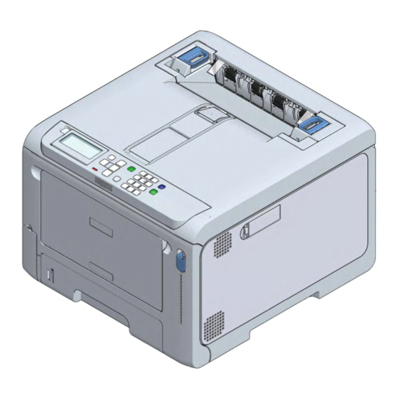
Basic operations Parts identification This section explains the name and functions of each part of the main unit. Front Name Function Front cover This is the cover on the front side of the main unit. You can open the front cover by pulling its lever towards yourself. Operator panel This is the panel used to operate the main unit. -
Page 67: Inside The Main Unit
Basic operations Inside the main unit Name Function Toner cartridge black (K: Black) The toner cartridge contains toner (powder ink) for printing. The toner cartridge is a consumable. Toner cartridge (C: Cyan) Toner cartridge (M: Magenta) Toner cartridge (Y: Yellow) Serial number The machine-specific number. -
Page 68: Back
Basic operations Back Name Function Rear output tray This is the paper exit when the paper is output with the print side facing up. Power connector This is where the included power cord is plugged in. Interface unit There is a connector to connect to a PC. USB interface connector This is where the USB cable is plugged in when the computer and the main unit is connected with a USB cable. -
Page 69: Turning The Power On/Off
Basic operations Turning the power on/off Turning the power on Press and hold the power switch for approx. one second. When the power is on, the LED lamp of the power switch will light on. When this machine gets ready, "Ready To Print" will appear on the display. Turning the power off Press and hold the power switch for approx. -
Page 70: Loading Paper
Basic operations Loading paper This section explains the types of paper applicable to this machine, paper precautions and paper storage methods. Procedure for loading paper 1. Check the applicable paper. Applicable paper(P.70) Inapplicable paper(P.72) 2. Load the paper in the tray. Paper applicable to each tray(P.74) Loading paper in Tray... - Page 71 Basic operations Media Type Paper size Paper weight Other conditions Long paper Custom Width: 55 - 216 Length: 91 - 1321 Envelope Com-9 Media using 24 lb paper Media made of craft paper, electrophotographic paper or dry PPC Com-10 paper. Monarch Media with the flap folded tightly.
-
Page 72: Inapplicable Paper
Basic operations Inapplicable paper Do not use the following types of paper. Doing so may cause paper jams or malfunction. Paper with smooth surface, rough paper, and paper with different front and back roughness Paper that is too thin or too thick ... - Page 73 Basic operations The toner may be easily removed. The printing quality may decline in an area of about 5 mm around the sealing part (of different weights) of the envelope. The warps on an envelope may cause poor paper feeding. Use the envelope after correcting warps or bulges.
-
Page 74: Paper Applicable To Each Tray
Basic operations If you cannot print correctly on a large-sized paper, it is suggested to set [Quality] to [Normal] in the PS printer driver. Always perform trial printing and check that there are no problems. Recycled The toner may stick thinly to the whole paper or the printing may be light. ... - Page 75 Basic operations Pull out the paper cassette. If you pull out the paper cassette with the power on, "Change tray settings?" may appear on the display. This message will disappear automatically in 10 seconds after the paper cassette is returned to the main unit. If you have changed the paper, press the «OK»...
-
Page 76: Loading Paper In Tray 2/3/4 (Optional)
Basic operations Return the paper cassette to this machine. If the paper cassette is returned to the main unit forcefully, the paper stopper may slide. Proceed to " (P.79)". Setting paper information on the operator panel Loading paper in Tray 2/3/4 (Optional) For the paper that can be used, please see "... - Page 77 Basic operations Be cautious for the orientation of paper that can be loaded in either portrait or landscape, like A5 size. Slide the paper guide and the blue part of the paper stopper to fit the size of the paper to be loaded.
-
Page 78: Loading Paper In The Mp Tray
Basic operations Loading paper in the MP tray For the paper that can be used, please see " (P.70)" and " (P.74)". Applicable paper Paper applicable to each tray Do not load paper of different sizes, types, and weight at the same time. ... -
Page 79: Setting Paper Information On The Operator Panel
Basic operations Adjust the manual feeder guide to the width of the paper to be loaded. Shuffle the paper well. Align edges of the paper horizontally. Load the paper with the print side facing up. Do not exceed the ▽ m ark on the paper guide when loading paper. "Would you like to change the tray settings?”... - Page 80 Basic operations If the machine is in the power save mode, press «POWER SAVE» to restore. For details about the short cut menu, see "Setting with the short menu (Fn key)(P.92)". For Tray 1/the MP tray Check that "Ready To Print" appears on the display. To set the paper size of Tray 1, press the keys in the following order: «Fn»...
-
Page 81: Storing Paper
Basic operations About values to be set Refer to the following table for settings in the case of plain, partially printed paper and colored paper. Values to be set on the operator panel Media type Media weight Plain 60 - 63 g/m paper: Ultra Light 64 - 74 g/m paper:Light... -
Page 82: Setting The Output Bin
Basic operations Setting the output bin This machine outputs paper to the output tray or rear output tray. The following types of paper can be output to each output tray. Output bin Types of paper to output Number of sheets to output Output tray Plain, recycled paper 150 (80 g/m... -
Page 83: Rear Output Tray
Basic operations Rear output tray Use the rear output tray to print on envelopes, labels or custom-sized paper. The paper is output with the printing side up in the reverse order to which they are printed. Open the rear output tray at the back of this machine. Open the paper supporter. -
Page 84: Checking The Configuration
Basic operations Checking the configuration You can print out and check the configuration of this machine. You can also check the configuration from the operator panel. Printing the menu map (configuration) You can print the list of configurations (menu map) of this machine or the Printer Usage Report. Check that "Ready To Print"... -
Page 85: Confirming On The Operator Panel
Basic operations For the information not listed in [Configuration], see "Menu list (User's Manual)" - [Print Information]. Confirming on the operator panel You can check the supplies status and counter information on the operator panel. Check that "Ready To Print" appears on the display. If the machine is in the power save mode, press «POWER SAVE»... -
Page 86: How To Use Levers L1 And L2
Basic operations How to use levers L1 and L2 When the front cover is open, you will find the L1 lever and the L2 lever. This section describe how to use these levers. Lever L1 Used to replace the image drum and to clean the LED head. Replacing the image drum(P.128) Cleaning the LED... - Page 87 Basic operations Lever L2 Used to replace the belt unit and to remove the jammed paper. Replacing the belt unit(P.133) When paper is jammed(P.148) After opening the front cover, pull the L2 lever. After the operation, both the output tray and the image drum basket are integrated and raised. Name Output tray Image drum basket...
-
Page 88: Changing Settings From The Operator Panel
Changing settings from the operator panel Changing settings from the operator panel Parts identification of the operator panel ..........89 Adjusting the display orientation .............. 90 Inputting text ..................... 91 Changing settings ..................92 Adjusting the buzzer volume ..............95 Setting the power save function ............... -
Page 89: Parts Identification Of The Operator Panel
Changing settings from the operator panel Parts identification of the operator panel Name Function Display Displays the state of this machine and operation instructions. There are two types of standby screens: "Show Remaining Toner" and "Show Tray Information". The factory default setting is "Show Remaining Toner". «ON LINE»... -
Page 90: Adjusting The Display Orientation
Changing settings from the operator panel Adjusting the display orientation You can adjust the angle so that it is easier to watch the display. Put your finger in the recess on the left side of the display, and raise the display towards you. To return to the original angle, press it gently. -
Page 91: Inputting Text
Changing settings from the operator panel Inputting text You can input alphabetic or numeric characters using the numeric keypad. If a same key is pressed in succession, the alphanumeric character will switch. To continue tying with the same key, press «OK» after inputting each alphanumeric character. -
Page 92: Changing Settings
Changing settings from the operator panel Changing settings Setting menu display This section describes how to change menu settings from the operator panel. See "Menu list (User's Manual)" for a list of menu items. Check that "Ready To Print" appears on the display. If the machine is in the power save mode, press «POWER SAVE»... - Page 93 Changing settings from the operator panel You can print to check the configuration. Printing the menu map (configuration)(P.84) Check that "Ready To Print" appears on the display. If the machine is in the power save mode, press «POWER SAVE» to restore. Press «Fn»...
- Page 94 Changing settings from the operator panel Function No. Corresponding menu item Media Type (Tray 4) Media Weight (Tray 4) Paper Tray Media Size (MP tray) X Dimension (MP tray) Y Dimension (MP tray) Media Type (MP tray) Media Weight (MP tray) Tray Usage (MP tray) Print Information (Menu Map (Configurations)) Print Information (Network)
-
Page 95: Adjusting The Buzzer Volume
Changing settings from the operator panel Adjusting the buzzer volume The volume of the following buzzers is adjustable in three steps. Paper jam buzzer Printing completion buzzer Buzzer for AirPrint printing IC Card hold buzzer Press the scroll button ▼ on the operator panel several times to select [Admin Setup], and press «OK». -
Page 96: Setting The Power Save Function
Changing settings from the operator panel Setting the power save function Setting the time that elapses before entering the power save mode This machine automatically enters the power save mode (an energy saving mode) if no operation is done for a certain period of time. -
Page 97: Restrictions Of The Power Save Function
Changing settings from the operator panel This machine may not enter the sleep mode after the set period of time since the fan is working until this machine has cooled down depending on the printing environment or the usage conditions. Check that "Ready To Print"... - Page 98 Changing settings from the operator panel [Auto Config]: The power is turned off automatically if the machine has not been used for a certain period of time, except in the following situations. When the LAN cable is connected to the network interface connector ...
-
Page 99: Setting The Time That Elapses Before Entering The Auto Power Off Mode
Changing settings from the operator panel Setting the time that elapses before entering the auto power off mode The following time can be set. The factory default setting is 4 hours. 1 hour, 2 hours, 3 hours, 4 hours, 8 hours, 12 hours, 18 hours, and 24 hours Check that "Ready To Print"... -
Page 100: Printing
Printing Printing Printing from a PC .................. 101 Screens and functions of the printer driver ..........103 - 100 -... -
Page 101: Printing From A Pc
For Windows PCL printer driver Open the file to be printed. Select [Print] from the [File] menu. Select [OKI C650 PCL6] from [Select Printer]. Click [Preferences] (or [Properties]). Select the loaded paper size from [Size] in the [Setup] tab. Select the tray to be printed from in [Paper Source]. -
Page 102: For Windows Ps Printer Driver
For Windows PS printer driver Open the file to be printed. Select [Print] from the [File] menu. Select [OKI C650 PS] from [Select Printer]. Click [Preferences] (or [Properties]). Select the [Paper/Quality] tab. Select the tray to be printed from in [Paper Source]. -
Page 103: Screens And Functions Of The Printer Driver
Printing Screens and functions of the printer driver Windows PCL printer driver [Setup] tab Item Description Driver settings Save the settings. Layout image Displays a sample image of the print layout. Size Sets the media size. Source Sets the paper source. Type Sets the media type. - Page 104 Printing [Job Options] tab Item Description Quality Specifies the print resolution. Scale Sets the enlargement/reduction of printing. Copies Specifies the number of copies. Job type Sets the type of printing. Print mode Sets whether the print data sent to the printer is in PCL format or as an image. Advanced Make other printing settings.
-
Page 105: Windows Ps Printer Driver
Printing Windows PS printer driver [Layout] tab Item Description Orientation Sets the printing orientation. Print on Both Sides Set for duplex printing. Page order Sets the order of pages to be printed. Page format Specifies the number of pages to be printed on one sheet of paper and booklet printing. - Page 106 Printing [Job Options] tab Item Description Quality Specifies the print resolution. Job Type Sets the type of print data and the number of copies. When [Shared Print] or [Private Print] is set, [Job Type Options] is available. If [Collate] is checked, multiple documents will be printed as a batch.
-
Page 107: Macos Printer Driver
Printing macOS printer driver [Layout] panel Item Description Pages per Sheet Selects the number of pages to be printed on one sheet of paper. Layout direction Specifies the layout for printing multiple pages on one sheet of paper. Border Specifies the type of borders. Two-Sided Specifies settings for printing on both sides. - Page 108 Printing [Paper Handling] panel Item Description Collate pages Checked to print a multi-page document in collation. Pages to print Specifies the pages to be printed. Page Order Specifies the order of pages to be printed. Scale to fit paper size Prints by fitting to the media size.
- Page 109 Printing [Cover Page] panel Item Description Print Cover Page Specifies the cover printing. Cover Page Type Specifies the text string for cover printing. [Color] panel Item Description Grayscale Print in monochrome. Color Specifies the color adjustment for colored printing. - 109 -...
- Page 110 Printing [Print Options] panel Item Description Quality1, Quality2, Feed, Specifies the print quality, toner save, media type, etc. Paper [User Authentication] panel Item Description Use user authentication Checked to set user authentication for printing. User name The user name for user authentication. Password The password for user authentication.
- Page 111 Printing [Secure Print] panel Item Description Job Type Specifies the type of print data. When [Private Print] or [Shared Print] is set, [Job Type Options] is available. Job Type Options Specifies the password for printing the job name displayed on the panel. [Supply Level] panel Item Description...
-
Page 112: How To Open The Printer Folder
Printing How to open the printer folder This section explains how to open the printer driver icon folder for each version of Windows. For Windows 10 (Version 1703 or later)/Windows Server 2019 Click [Start] to display the application list. Select [Windows System Tool] - [Control Panel] - [Devices and Printers]. For Windows Server 2012 R2/Windows Server 2016 Select [Control Panel] - [View devices and printers]. -
Page 113: Management Of This Machine
Management of this machine Management of this machine Admin password ..................114 - 113 -... -
Page 114: Admin Password
Management of this machine Admin password The admin password is used to change the settings of the machine. We recommend you to change the admin password to protect your personal information. Checking the factory default admin passwords The factory default admin password is set to a 10-digit value of this machine's serial number with upper-case letters converted to lower-case ones. - Page 115 Management of this machine Check that [Serial Number] is selected, and press «OK». Check the 10-digit alphanumeric characters displayed in [Serial Number]. Convert the upper-case letters of [Serial Number] into lower-case ones and use the converted string as the admin password. Checking by printing the menu map ...
-
Page 116: Inputting The Factory Default Admin Passwords
Management of this machine Check the leftmost 10 digits of the alphanumeric characters written on the sticker on the left to the L2 lever. You may convert the upper-case letters into lower-case ones and use the converted string as the admin password. -
Page 117: Changing The Admin Password
Management of this machine Press «OK» again to complete inputting the admin password and display [Admin Setup]. Changing the admin password The admin password can consist of 1 to 32 digits. The following characters can be used for the admin password. ... - Page 118 Management of this machine Press «OK» again to display the [Verify Password] screen. Input the password again, and press «OK». When «OK» is pressed again, the password has been changed and the screen returns to [Admin Setup]. Admin password memo field - 118 -...
-
Page 119: Maintenance
Maintenance Maintenance Precautions for replacing consumables ..........120 Service life and replacement cycle of consumables ......121 Replacing the black(K) toner cartridge and the waste toner box ... 123 Replacing the toner cartridge (C/M/Y) ............ 126 Replacing the image drum ..............128 Service life and replacement cycle of maintenance parts ...... -
Page 120: Precautions For Replacing Consumables
Store the used toner cartridge and the waste toner box in a bag so that toner does not scatter. Use genuine OKI consumables for optimum performance. Failures caused by using non-genuine consumables may void the warranty or maintenance contract. (The use of non-genuine consumables will not necessarily cause failures, but please fully take notice of such usage.) -
Page 121: Service Life And Replacement Cycle Of Consumables
Printing quality will decline after the toner cartridge stays unpacked for one year or longer. Therefore, prepare a new toner cartridge. Use genuine OKI consumables for optimum performance. Failures caused by using non-genuine consumables may void the warranty or maintenance contract. (The use of non-genuine consumables will not necessarily cause failures, but please fully take notice of such usage.) - Page 122 Do not expose the image drum to direct sunlight or strong light (About 1,500 lux or above). Do not leave it uncovered for more than 5 minutes even under room lighting. Use genuine OKI consumables for optimum performance. Failures caused by using non-genuine consumables may void the warranty or maintenance contract. (The use of non-genuine consumables will not necessarily cause failures, but please fully take notice of such usage.)
-
Page 123: Replacing The Black(K) Toner Cartridge And The Waste Toner Box
Maintenance Replacing the black(K) toner cartridge and the waste toner The black(K) toner cartridge comes with a waste toner box. By following on-screen instructions, replace the waste toner box first and then the black(K) toner cartridge. Press the knob on the lower left corner on the front of the machine, and open the waste toner box cover toward you. - Page 124 Maintenance Take the new black(K) toner cartridge out of its packing box. Shake the new toner cartridge both horizontally and vertically for several times. Pull the front cover open lever (blue) to open the front cover. Pull out the black(K) toner cartridge from the machine. Install the new black(K) toner cartridge into the machine.
- Page 125 Maintenance Press «OK». Check that no error message appears on the display. Please recycle the used toner cartridge and waste toner box. - 125 -...
-
Page 126: Replacing The Toner Cartridge (C/M/Y)
Maintenance Replacing the toner cartridge (C/M/Y) This section takes the toner cartridge (M) as an example. The toner cartridge (C/Y) can be replaced by the same procedure. To replace the black toner cartridge (K), please refer to "Replacing the black(K) toner cartridge and the waste toner box(P.123)". - Page 127 Maintenance Close the front cover firmly with your both hands. Please recycle the used toner cartridge. - 127 -...
-
Page 128: Replacing The Image Drum
Maintenance Replacing the image drum Pull the front cover open lever (blue) to open the front cover. Pull the L1 lever towards you until the red triangle mark on the L1 lever is aligned with the red triangle mark inside the machine. If the two red triangle marks are not aligned correctly, you cannot proceed to the procedure of replacing the image drum. - Page 129 Maintenance Check the image drum to be replaced by the label color. Remove the image drum of the color to be replaced. Because image drums (green parts) can easily get damaged, handle with adequate care. Do not expose the image drum to direct sunlight or strong light (About 1,500 lux or above). Do not leave it uncovered for more than 5 minutes even under room lighting.
- Page 130 Maintenance Hold the L3 handle and push the image drum basket all the way in. If the image drum is not installed correctly, the image drum basket cannot be pushed all the way in. The output tray cannot be closed unless the image drum basket is pushed all the way in. Close the output tray, and push both sides down from top.
-
Page 131: Service Life And Replacement Cycle Of Maintenance Parts
Maintenance Service life and replacement cycle of maintenance parts Belt unit Service life of the belt unit The belt unit can print approximately 60,000 sheets of A4-sized paper (for simplex printing), but the actual printable number of sheets may vary with the usage condition. The above number is based on the general usage condition (three sheets at a time). -
Page 132: Fuser Unit
Maintenance Fuser unit Service life of the fuser unit The fuser unit can print approximately 60,000 sheets of A4-sized paper (for simplex printing), but the actual printable number of sheets may vary with the usage condition. The above number is based on the general usage condition (three sheets at a time). If you print a single sheet at a time, the life may be reduced by half. -
Page 133: Replacing The Belt Unit
Maintenance Replacing the belt unit For the replacement cycle, see " (P.131)". Belt unit Pull the front cover open lever (blue) to open the front cover. Pull the L2 lever and lift the output tray to the stop position. Remove the belt unit by holding its blue handle. Doing so may cause burns. - Page 134 Maintenance Install the belt unit in this machine by holding its blue handle. Close the output tray, and push both sides down firmly from top. Close the front cover firmly with both hands. Please recycle the used belt unit. - 134 -...
-
Page 135: Replacing The Fuser Unit
Maintenance Replacing the fuser unit For the replacement cycle, see " (P.132)". Fuser unit Lift the left and right handles of the fuser unit at the back of the output tray until a click is heard, and then release the lock. The fuser unit cannot be removed unless its handle is raised vertically. - Page 136 Maintenance With the warning label of the new fuser unit facing the front, hold both the left and right handles and install the fuser unit into this machine. Push down the left and right handles of the fuser unit to lock. Make sure that the fuser unit does not float from the top of the output tray.
-
Page 137: Cleaning The Main Unit And The Parts
Maintenance Cleaning the main unit and the parts Cleaning the LED head If there are white stripes on the output paper, the image is faded or the text is blurred, clean the LED head. Do not use methyl alcohol or thinner. Doing so may damage the LED head. ... -
Page 138: Cleaning The Surface Of The Main Unit
Maintenance Gently wipe the lens surface of the LED head (x 4) with a soft tissue paper. Do not expose the image drum to direct sunlight or strong light (About 1,500 lux or above). Do not leave it uncovered for more than 5 minutes even under room lighting. Close the output tray, and push both sides down from top. -
Page 139: Cleaning Paper Feed Rollers (Trays 1-4)
Maintenance Clean the surface of this machine with a cloth slightly moistened with water or a neutral detergent. Only use water or a neutral washing agent. Wipe the surface of this machine with a soft dry cloth. Cleaning paper feed rollers (Trays 1-4) If paper jams occur frequently, clean the paper feed roller. -
Page 140: Cleaning The Paper Feed Roller (Mp Tray)
Maintenance Wipe the separation roller of the cassette with a cloth slightly moistened with water. Load the paper in the paper cassette. Return the paper cassette to this machine. Cleaning the paper feed roller (MP tray) If paper jams occur frequently, clean the paper feed roller. ... - Page 141 Maintenance While lifting the MP tray gently, press the right arm inwards and remove the protrusion of the arm from the groove. Lower the MP tray, and lift up the protrusion of the arm. By referring to Steps 3 and 4, remove the protrusion of the left arm of the MP tray from the groove and lift it up.
- Page 142 Maintenance Press down on the center of the MP tray, place your finger over the small window on the separation roller cover and push it up to remove the separation roller. Wipe the separation roller with a cloth slightly moistened with water (while rotating it in the arrow direction).
- Page 143 Maintenance Press down on the center of the MP tray, and then press and hold the white part which is visible through the small window at the bottom of the separation roller cover. With the protrusion side on the left, install the paper feed roller (without gear) onto the lower shaft by sliding it into the innermost position.
-
Page 144: Cleaning The Light-Shielding Film
Maintenance While pressing the right arm of the MP tray inwards, lift the MP tray lightly and hook the protrusion of the arm into the groove. If you close the MP tray without hooking the protrusion of the arm to the correct position, the paper placement cover may be broken. -
Page 145: Cleaning The Resist Roller
Maintenance Install the image drum to this machine. Replacing the image drum(P.128) Clean the light-shielding film of other image drums as well. Cleaning the resist roller When horizontal streaks appear on the printing result, clean the resist roller to improve the printing. Pull the front cover open lever (blue) to open the front cover. -
Page 146: Troubleshooting
Troubleshooting Troubleshooting When an error message appears on the display ........147 When paper is jammed ................148 - 146 -... -
Page 147: When An Error Message Appears On The Display
Troubleshooting When an error message appears on the display If a problem occurs to this machine, the ATTENTION lamp will light on or flash, and a message will appear on the display. Check the message on the display and take action based on the corresponding message. If [Please see HELP for details] appears at the bottom of the display, press «HELP»... -
Page 148: When Paper Is Jammed
Troubleshooting When paper is jammed For the error code 370 or 371 Remove the jammed paper from the output exit. Pull the front cover open lever (blue) to open the front cover. Pull the L2 lever and lift the output tray until it reaches the stop position. Remove the paper left on the belt unit if any. - Page 149 Troubleshooting Lift the belt unit up by holding its handle. Remove the paper left under the belt unit if any. Reset the belt unit. Close the output tray, and push both sides down from top. Lift the left and right handles of the fuser unit at the back of the output tray until a click is heard, and then release the lock.
- Page 150 Troubleshooting Remove the fuser unit from this machine by holding its left and right handles. Doing so may cause burns. When the fuser unit is hot, wait until it cools down before any operation. Do not expose this machine with the fuser unit removed to direct sunlight or strong light (About 1,500 lux or above).
-
Page 151: For The Error Code 372
Troubleshooting With the warning label of the fuser unit facing you, hold both the left and right handles. Place the fuser unit in this machine, tilt its left and right handles inward, and lock the fuser unit. Make sure that the fuser unit does not float from the top of the output tray. If floating, the fuser unit will not be recognized so that it is not possible to start printing. - Page 152 Troubleshooting Pull the front cover open lever (blue) to open the front cover. Pull the L2 lever and lift the output tray until it reaches the stop position. Remove the paper left on the belt unit if any. Doing so may cause burns. Do not touch the fuser unit because it is hot.
-
Page 153: For The Error Code 380
Troubleshooting Remove the paper under the belt unit if any. Reset the belt unit. Close the output tray, and push both sides down from top. Close the front cover firmly with both hands. For the error code 380 Pull the front cover open lever (blue) to open the front cover. - 153 -... -
Page 154: For The Error Code 381
Troubleshooting Pull out the jammed paper gently. Close the front cover firmly with both hands. For the error code 381 Remove the jammed paper from the output exit. Pull the front cover open lever (blue) to open the front cover. Pull the L2 lever and lift the output tray until it reaches the stop position. -
Page 155: For The Error Code 382 Or 385
Troubleshooting Remove the paper on the belt unit if any. Doing so may cause burns. Do not touch the fuser unit because it is hot. Because image drums (green parts) can easily get damaged, handle with adequate care. Do not expose the image drum to direct sunlight or strong light (About 1,500 lux or above). Do not leave it uncovered for more than 5 minutes even under room lighting. - Page 156 Troubleshooting Pull the front cover open lever (blue) to open the front cover. Pull the L2 lever and lift the output tray until it reaches the stop position. Remove the paper left on the belt unit if any. Doing so may cause burns. Do not touch the fuser unit because it is hot.
- Page 157 Troubleshooting Lift the left and right handles of the fuser unit at the back of the output tray until a click is heard, and then release the lock. The fuser unit cannot be removed unless its handle is raised vertically. Holding both the left and right handles of the fuser unit, remove the fuser unit from this machine.
- Page 158 Troubleshooting If paper is jammed in the fuser unit, with the warning label of the fuser unit facing you, slowly pull out the jammed paper towards you. Doing so may cause burns. When the fuser unit is hot, wait until it cools down before any operation. Do not pull out in the reverse direction.
-
Page 159: For The Error Code 390
Troubleshooting For the error code 390 Temporarily remove any paper loaded in the multi-purpose tray (MP tray). Pull the front cover open lever (blue) to open the front cover. Hold the edge of the jammed paper and pull it out gently. When the top edge is not visible, slowly pull out the paper from its rear edge. - Page 160 Troubleshooting If paper jams occur frequently, clean the paper feed roller. Please see "Cleaning paper feed rollers (Trays 1-4)(P.139)" for details. Pull out the paper cassette. Remove the jammed paper. If no paper is jammed, feeding has failed. Reduce the number of paper loaded in the paper cassette. Also, make sure that the paper stopper position matches the paper size.
-
Page 161: For The Error Code 638
Troubleshooting For the error code 638 First, check all the trays and remove the remaining paper. Then, remove the remaining paper inside the machine. This section explains how to remove the paper from Tray 2 as an example. Pull out the paper cassette. Remove the remaining paper. - Page 162 Troubleshooting Pull the front cover open lever (blue) to open the front cover. Pull out the jammed paper slowly if any. Pull the L2 lever and lift the output tray until it reaches the stop position. Remove the paper left on the belt unit if any. Doing so may cause burns.
- Page 163 Troubleshooting Lift the belt unit up by holding its handle. Remove the paper left under the belt unit if any. Reset the belt unit. Close the output tray, and push both sides down from top. Lift the left and right handles of the fuser unit at the back of the output tray until a noise is heard, and then release the lock.
- Page 164 Troubleshooting Holding both the left and right handles of the fuser unit, remove the fuser unit from this machine. Doing so may cause burns. When the fuser unit is hot, wait until it cools down before any operation. Do not expose this machine with the fuser unit removed to direct sunlight or strong light (About 1,500 lux or above).
- Page 165 Troubleshooting Place the fuser unit in this machine, tilt its left and right handles inward, and lock the fuser unit. Make sure that the fuser unit does not float from the top of the output tray. If floating, the fuser unit will not be recognized so that it is not possible to start printing.
-
Page 166: Appendix
Appendix Appendix Specifications ..................167 Dimensions ..................... 171 Menu tree ....................173 - 166 -... -
Page 167: Specifications
Appendix Specifications Model Model Number C650, ES6450 N36800A, N36800B General specifications Item C650/ES6450 ARM processor (667 MHz) Memory Built-in DDR3 32bit 1GB Weight (with consumables) Approx. 28 kg Dimensions (WxDxH) 395 × 430 × 290 mm Power N36800A: 110V - 127V AC +/-10%... - Page 168 Appendix Item C650/ES6450 First page output Color Approx. 6.5 sec (A4) time Mono Approx. 6.5 sec (A4) Media Size Tray 1 A4, A5, A6, B5, B6, Letter, Legal 13/13.5/14, Executive, Statement, 8.5-inch SQ, Folio, 16K (197 x 273 mm, 195 x 270 mm, 184 x 260 mm), 5 x 7 inches, custom sizes Expansion tray A4, A5, A6, B5, B6, Letter, Legal 13/13.5/14, Executive, Statement, 8.5-inch SQ,...
-
Page 169: Regulatory Wireless Lan Statements
Appendix Item C650/ES6450 Maintenance parts Belt unit, fuser unit *1:Standard-sized paper Specifications of the expansion tray unit Item Expansion tray unit Weight Approx. 6.0 kg Dimensions 395 mm (W) x 450 mm (D) x 139 mm (H) Network specifications Item... - Page 170 Appendix IC statement This device complies with Part 15 of FCC Rules and Industry Canada licence-exempt RSS standard(s). Operation is subject to the following two conditions: (1) this device may not cause interference, and (2) this device must accept any interference, including interference that may cause undesired operation of this device. Le présent appareil est conforme aux la partie 15 des règles de la FCC et CNR d'Ubdustrie Canada applicables aux appareils radio exempts de licence.
-
Page 171: Dimensions
Appendix Dimensions Plan view Side view - 171 -... - Page 172 Appendix With options installed - 172 -...
-
Page 173: Menu Tree
Appendix Menu tree Functions Print From USB Memory Print Setup Paper Feed Copies Duplex Binding Color Mode Barcode Print Setup Repeat Layout Rows Layout Columns Start Position X Coordinate Y Coordinate Spacing X Spacing Y Spacing Barcode Type Barcode Attribute Error Correction Level Module Size Human Readable Character... - Page 174 Appendix System Serial Number Asset Number Lot Number Firmware Version CU Version PU Version Panel Version Flash Memory Date and Time Print Information Configuration (Fn100) Network (Fn101) File List PS Font List PCL Font List IBM PPR Font List EPSON FX Font List Usage Report (Fn102) Supplies Report Error Log (Fn103)
- Page 175 Appendix Tray2 (Fn222) X Adjust Y Adjust Duplex X Adjust Duplex Y Adjust Tray3 (Fn223) X Adjust Y Adjust Duplex X Adjust Duplex Y Adjust Tray4 (Fn224) X Adjust Y Adjust Duplex X Adjust Duplex Y Adjust Paper Black Setting (Fn230) Paper Color Setting (Fn231) Trans.
- Page 176 Appendix Tray Configuration MPTray Config Paper Size (Fn90) X Dimension (Fn91) Y Dimension (Fn92) Media Type (Fn93) Media Weight (Fn94) Tray Usage (Fn95) Tray1 Config Paper Size (Fn10) X Dimension (Fn11) Y Dimension (Fn12) Media Type (Fn13) Media Weight (Fn14) Tray2 Config Paper Size (Fn20) X Dimension (Fn21)
- Page 177 Appendix Print Setup Personality Copies Duplex Binding Media Check A4/Letter Override Resolution Toner Save Level Toner Save Color Mono-Print Mode Color Ready Mode Default Orientation Edit Size Trapping X Dimension Y Dimension PS Setup L1 Tray Network Protocol USB Protocol PDF Paper Size PDF Print Mode PCL Setup...
- Page 178 Appendix Color Setup Ink Simulation CMY 100% Density CMYK Conversion Panel Setup Near Life Status Near Life LED Idle Display Panel Contrast Buzzer Setup Error Volume Print Completion Buzzer Volume AirPrint Buzzer Volume Card Hold Buzzer Volume Time Setup Date Format Time Zone Daylight Saving Setting method...
- Page 179 Appendix AirPrint Wireless(Infrastructure) Setting Wireless(Infrastructure) You must input an administrator Network Setting IP Address Set password. IPv4 Address Subnet Mask Gateway Address DHCPv6 Automatic setup (WPS) WPS-PBC WPS-PIN Wireless Network Selection xxxxxx Manual Setup SSID Security WEP Key WPA Encryption Type WPA Pre-shared Key Execute Wireless reconnection...
- Page 180 EE8001-1659Z002 Rev2...