Table of Contents
Advertisement
Quick Links
IMPORTANT SAFETY INFORMATION: Always read this manual first before attempting to service this cassette. For your
safety, always comply with all warnings and safety instructions contained in this manual to prevent personal injury or prop-
erty damage.
Dimplex North America Limited
1367 Industrial Road Cambridge ON Canada N1R 7G8
1-888-346-7539 www.dimplex.com
In keeping with our policy of continuous product development, we reserve the right to make changes without notice.
© 2013 Dimplex North America Limited
Service Manual
Model
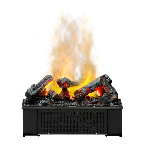
DFI400L
DFI400R
DFI600L
Part Number
6909050241
6909050242
6909050261
REV
PCN
DATE
00
-
1-NOV-13
7400770000R00
Advertisement
Table of Contents

Related Manuals for Dimplex DFI400L


Summary of Contents for Dimplex DFI400L
- Page 1 Dimplex North America Limited 1367 Industrial Road Cambridge ON Canada N1R 7G8 1-NOV-13 1-888-346-7539 www.dimplex.com In keeping with our policy of continuous product development, we reserve the right to make changes without notice. © 2013 Dimplex North America Limited 7400770000R00...
-
Page 2: Table Of Contents
NOTE: Procedures and techniques that are considered important enough to emphasize. CAUTION: Procedures and techniques which, if not carefully followed, will result in damage to the equipment. WARNING: Procedures and techniques which, if not carefully followed, will expose the user to the risk of fire, serious injury, or death. www.dimplex.com... -
Page 3: Operation
OPERATION Figure 2 Figure 1 Standby Button Button Remote Control Sensor Battery Cover Remote Control NOTE: Always ensure that the appliance is in an upright The On/Off Switch must be in the ‘ON’ ( I ) position in order position before operating the unit. for the remote control to operate. -
Page 4: Maintenance
Light bulb requirement: 45W, 12VAC halogen bulbs type MR servicing. 16. Contact Dimplex Technical Service at 1-888-346-7539 for replacement bulbs. Leaving the flame effect on, remove the media (if appli- Figure 3... -
Page 5: Exploded Parts Diagram
EXPLODED PARTS DIAGRAM REPLACEMENT PARTS LIST 14. Transducer ..... 3800040100RP 1. Remote Control ....9600800100RP 15. -
Page 6: Wiring Diagram
WIRING DIAGRAM WHITE WHITE BLACK MAINS 3 CORE CABLE TRANSDUCER MALE JACK DC FAN MOTOR www.dimplex.com... -
Page 7: Remote Control Receiver Replacement
REMOTE CONTROL RECEIVER Figure 4 REPLACEMENT Tools Required: Philips head screwdriver Flat Head Screwdriver Transformers WARNING: Disconnect power before attempting any maintenance to reduce the risk of electric shock or damage to persons. NOTE: Ensure that all of the components that contain water have been emptied before performing any maintenance. -
Page 8: Potentiometer Replacement
NOTE: Ensure that all of the components that release the wires. contain water have been emptied before performing any 4. With needle nose pliers, grasp the cord strain relief maintenance. grommet from inside the back of the bottom panel and www.dimplex.com... - Page 9 1. Disconnect and remove the media from the unit and Figure 6 put them in a safe place. 2. Disassemble the sump components. (Figure 3) 3. Remove the 3 screws that hold the cover onto the fan housing. (Figure 6) 4.
-
Page 10: Troubleshooting Guide
Filter is missing off of Fan Housing Replace Fan Filter Mist does not appear to be com- Unit is not level Level unit ing out evenly Media is blocking air flow Rearrange media A light bulb is burnt out Replace light bulb www.dimplex.com...