Advertisement
Quick Links
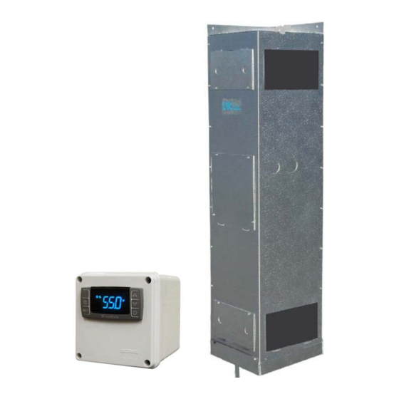
Split Water-Cooled Rack-Recessed Cooling System
Operation Care Installation Manual
Read and save these instructions
Vinotemp International Corp
732 South Racetrack Road, Henderson, NV 89015
Tel: (800) 777-VINO Fax: (310) 886-3310 Email: info@vinotemp.com
WM-2500SSVWC
WM-4500SSVWC
WM-6500SSVWC
www.vinotemp.com
Advertisement

Related Manuals for Vinotemp WINE-MATE WM-2500SSVWC


Summary of Contents for Vinotemp WINE-MATE WM-2500SSVWC
- Page 1 Split Water-Cooled Rack-Recessed Cooling System Operation Care Installation Manual WM-2500SSVWC WM-4500SSVWC WM-6500SSVWC www.vinotemp.com Read and save these instructions Vinotemp International Corp 732 South Racetrack Road, Henderson, NV 89015 Tel: (800) 777-VINO Fax: (310) 886-3310 Email: info@vinotemp.com...
- Page 2 Important Safety Information WARNING To avoid the risk of electrical shock, property damage, personal injury, or death: • The power cord must be plugged into a 3-prong grounding type wall receptacle, grounded in accordance with the National Electrical Code, ANSI/NFPA 70 – latest edition and local codes and ordinances. •...
-
Page 3: Table Of Contents
Table of Contents Cellar Construction Guide Features & Specifications Temperature & Humidity Care Guide User’ Troubleshooting Installer’s Instructions Electrical Wirings Warranty------------------------------------------------------------------ 27... -
Page 4: Cellar Construction Guide
Cellar Construction Guide This is only a guide and shall be considered as the minimum requirements. All interior walls, ceilings and floors shall have a vapor barrier and a minimum of R13 insulation. All exterior walls and ceiling shall have a vapor barrier and a minimum of R19 insulation. -
Page 5: Features & Specifications
Features and Specifications • WM-2500~6500SSVWC split water-cooled rack-recessed cooling systems are designed to provide a cold environment between 50~65 °F with a humidity range within 50~70% RH for a properly insulated wine cellar. • These temperature and humidity ranges are optimized for long term storage of wine like that in natural caves. - Page 6 CAUTION The condensing unit must operate above 32°F ambient temperature. NOTE The cooling capacity is determined under 55°F cellar temperature, 75°F cellar ambient temperature and 90°F condensing unit ambient temperature, with R13 interior and R19 exterior insulations. Higher ambient temperatures or lower insulations will cause reducing capacity and the cellar temperature may not be maintained at 55°F.
-
Page 7: Temperature & Humidity
Temperature and Humidity 1. The controller Fig. 2 TEMPERATURE CONTROLLER 1) Keys SET: To display set-point; in programming mode it selects a parameter or confirms an operation. : To start a manual defrost. : To see the maximum stored temperature; in programming mode it browses the parameter codes or increases the displayed value. - Page 8 4) Alarm Signals The alarm codes are described as follows. MESSAGE CAUSE FUNCTION Temperature probe Compressor switching to Con and faulty High temperature Probe temperature ALU higher than alarm setting temperature; Outputs unchanged Low temperature Probe temperature ALL lower than alarm the setting temperature;...
- Page 9 5. Manual Defrost Press and hold the defrost key until defrost starts. The defrost indicator will be 6. Parameter Programming keys until the “°C” or “°F” LED starts flashing, 1) Press and hold the SET + then release the keys. 2) Press and hold again the SET + keys until the Pr2 label is displayed, then release the keys.
- Page 10 7. How to calibrate the air probe If the actual cellar temperature differs from the setting temperature, set parameter ot = actual cellar temperature minus set-point. 8. How to adjust defrost settings In case there is excessive frost, the parameters FnC = C-y, idF = 4 and MdF = 20 can be used to avoid frost.
-
Page 11: Care Guide
Care Guide In general, always unplug system or disconnect power while doing care. 1. Condenser Water Line Cleaning • To clear any sediment that may accumulate, the water regulating valve may be manually flushed. • Insert screwdrivers under both sides of the valve spring guide and lift upwards to flush. -
Page 12: User' Troubleshooting
User’s Troubleshooting This Troubleshooting Chart is not prepared to replace the training required for a professional refrigeration service person, not is it comprehensive. Complaint Possible Causes Response 1. Unit not running Power cord not plugged Check power cord No power from supply Check receptacle and fuses Incorrect or loose wirings Check all wirings and connections... - Page 13 Dirty Condenser Clean condenser Improper condenser cooling Check for water flow Iced evaporator Defrost and reset temperature Refrigeration system restriction Call service Refrigerant leak Call service Undercharge or overcharge Call service Failed components Call service 7. Unit running too a. Improper cellar insulation & seal a.
- Page 14 condensate c. Drain restricted c. Clean the drip tray and drain line 15. Condensate Drain line restricted Check for drain inside ducts Continually running not raise temperature setting stopping increase defrost Increase flow raise Too cold supply air temperature setting Duct not insulated Check for insulation 16.
-
Page 15: Installer's Instructions
WINE~MATE split system is shipped as components and is ready for use only after a certified refrigeration technician has properly installed the system. Proper installation is critical. Vinotemp can only warrant the quality of the components. The installation and proper operation of the system must be warranted by the installer. - Page 16 Parts not included: Liquid line copper tubing Suction line copper tubing Water lines Insulated Ducts CAUTION Liquid and suction line locations may differ from that what is shown below, please check on the units for proper installations. To prepare rough-in, leave minimum 4” clearances for electrical NOTE wiring and refrigeration piping.
- Page 17 Fig. 4 WM-25~65SFCV Evaporator Unit -16-...
- Page 18 Fig. 5 WM-250~650SCUR-WC Condensing Unit Fig. 6 WM-Liquid Filter Fig. 7 WM-Liquid Indicator 2. Temperature Controller and Air Probe Location 1) The temperature controller can be mounted either inside or outside the wine cellar, but the air probe must be located inside the wine cellar or the return duct. 2) The air probe shall be located in the wine cellar 5 ft above the floor or the air return area, but it shall not be located in the air supply area or other areas where air is not circulated.
- Page 19 1) The WM-25~65SFCV evaporator units should be installed for corner mount with the supply air on the top and return air on the bottom. 2) Air supply shall be unobstructed minimum 12”; air return shall be unobstructed minimum 6”. 3) A grille can be used to cover the supply and return with 0~2” clearance; or a 2- 3 ft long duct can be added at the supply and return.
- Page 20 2) If the line set exceeds 75 ft long, use both inverted U trap and suction accumulator to prevent liquid from flooding back to the compressor. 3) If the condensing unit is located below the evaporator unit, use inverted U trap to prevent liquid from flooding back to the compressor.
- Page 21 BACK POSITION FRONT POSITION MIDDLE POSITION Fig. 9 Base Valve Operation Back Position: Normal operation, manifold port is closed. Front Position: Storage operation, liquid or suction line connection is closed. Middle Position: Installation operation, all ports are open. NOTE The recommended initial charges are used for reference only, always use the superheat, subcooling and pressure readings to charge refrigerant properly.
- Page 22 Fig. 10 Water Regulating Valve 2) Checking pressure control settings Suction pressure setting: Cut out=5 psig; Cut in=25 psig; Differential=20 psig Head pressure setting: Cut out=230 psig; Cut in=150 psig; Differential=80 psig It is necessary to adjust the setting in the field to reach the correct cycle time. Fig.
- Page 23 Fig. 12 Fan Speed Control 4) The subcooling at the condensing unit shall be around 10°F. The charge may be complete when there are no more bubbles forming in the liquid indicator. 5) Head pressure is maintained constant but will vary with the water outlet temperature: 120 ~ 190 psig at the water outlet temperature 95 ~ 120 °F.
- Page 24 10. Pressure, Superheat and Subcooling Readings To read properly, the service valves must be in the middle CAUTION positions. Complaint Possible Causes 1) Compressor may be bad 1) High suction pressure and low head pressure Zero superheat and zero subcooling 2) High suction pressure and low 2) Expansion valve opened, too head pressure...
- Page 25 High superheat and high subcooling and suction lines connected wrong suction pressure and high head Liquid line restricted pressure before receiver High superheat and high subcooling low to normal suction pressure and high Condenser restricted head pressure Normal high superheat high subcooling 11.
-
Page 26: Electrical Wirings
Electrical Wiring Diagrams Hidden lines are the field wirings CAUTION Use minimum 14 gauge wires for power lines. If equipped with low ambient condition kit, use low ambient temperature wiring diagrams. A safety switch is always recommended for the condensing unit. Fig. - Page 27 Fig. 15 WM-6500SSVWC Electrical Wiring Diagram -26-...
-
Page 28: Warranty
BTU/H. While every effort has been made to provide accurate guidelines, VINOTEMP can not warranty its units to cool a particular enclosure. In case of failure, VINOTEMP cooling units must be repaired by the factory or its authorized agent. Repairs or modifications made by anyone else will void the warranty. - Page 29 VINOTEMP will, at its discretion, repair or replace the unit and return it free of charge to the original retail customer. If the unit is found to be in good working order, or beyond the initial twelve month period, it will be returned freight collect.