
Summary of Contents for Tronic TR10250
- Page 1 Residential ESS Battery Cabinet TR10250 | TR20450 | TR30750| TR40950 Quick Guide TRONIC ESS CO., LTD...
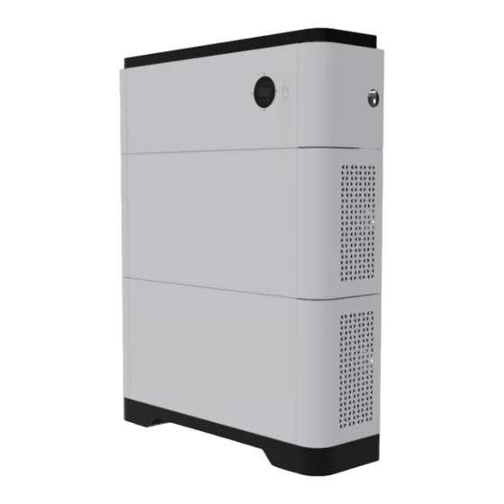
- Page 2 Product Overview 1.1 ESS Battery Cabinet Product Appearance ESS Battery Cabinet is applicable to the grid-tied or off-grid systems. It can store and release electric energy based on service requirements. Top Cover DC Switch Power control module Battery expansion module (5.12kWh)...
- Page 3 Front View Right View Left View Power control module (1)Mounting handle (2)Internal COM port 1 (3)Battery cascading terminal(+) (4)Battery cascading terminal(-) (5)Internal COM port 2 Product diagram (1)Top cover (2)Protective cover (3)Power control module (4)Battery expansion module (5)Bottom cover...
- Page 4 1.2 ESS Battery Cabinet Model TRONIC ESS has different electricity products to meet user’s needs, such as TR10250、TR20450、TR30750、TR40950. 1.3 Technical data...
- Page 5 1.4 System Schematic...
-
Page 6: Device Installation
Device Installation 2.1 Installation Requirements 2.1.1 Installation Environment 2.1.2 Installation Space unit:mm inverter front≥1000mm... - Page 7 2.1.3 Mounting Hole Dimensions unit:mm...
- Page 8 2.2 Installation and fixation Place the base in a horizontal position, then put the battery unit on the base. (Note: pay attention to the red circle mark in the figure, the battery unit and the base should be completely consistent to prevent dislocation). Using a fixing piece to fix the battery unit with the base.
- Page 9 Place the remaining battery units and power control units respectively. (Note: when fixing the component unit, the torque shall not exceed 1.2N. M to prevent equipment damage. When fixing the wall, the torque shall not exceed 1.2N. M; The power control unit is placed on the battery unit. The legend is jk20450 product.
- Page 10 Internal Electrical Connections of the Battery Note: A. The internal connecting wires are packed in the box; B. Before connecting cables, ensure that the switches of the devices are turned off. Otherwise, high voltage electric shock and equipment damage may be caused. 3.1 Connection of Battery Cable The battery expansion modules in the ESS battery cabinet are ...
- Page 11 External Electrical Connections of the Battery Note: A. The internal connecting wires are packed in the box; B. Before connecting cables, ensure that the switches of the devices are turned off. Otherwise, high voltage electric shock and equipment damage may be caused. 4.1 cable specification ConductorCross- Cable...
- Page 12 4.3 COM Port Pin Definitions Definition note External CANH Communicate with inverter CAN External CANL RS485-A Communicate with inverter 485 RS485-B...
-
Page 13: Verifying The Installation
Verifying the Installation 5.1 Installing Cover After electrical connections are complete, check that cables are correctly and securely connected, install the external protective cover, and secure it using screws. Acceptance Criterion The battery is installed correctly and securely. The cables are routed properly as required by the customer. Cable ties are secured evenly and no burr exists. -
Page 14: Power-On Commissioning
6 Power-On Commissioning Confirm the connection between ESS battery cabinet and inverter before power on for the first time starting. Turn the isolation switch of ESS battery cabinet and inverter switch to "on" (refer to inverter manual for specific inverter operation). Press the start button. - Page 15 See the table below for status indication System Abnormal Note state event Lights out Lights out Lights out Standby Normal Light on Lights out Light on / display percentage Alarm Light on Twinkle according to electric quantity Discharge Lights out Light on Lights out protection...
- Page 16 7 Tool & safety gears required 1. Tools The following tools are required to install the battery pack: Precision screwdriver Drill Pencil or Marker 2. Safety gears for personal protection It is recommended to wear the following safety gears when handling the battery pack.
- Page 17 8 Inverter Matched inverter brand and model Brand Type Note GW3600-EH GW5000-EH GW6000-EH GOODWE GW5K-ET GW8K-ET GW10K-ET STH-3KTL-HSS STH-3.6KTL-HSS STH-3KTL-HS STH-3.6KTL-HS STH-4.2KTL-HS SUNWAYS STH-4.6KTL-HS STH-5KTL-HS STH-6KTL-HS STH-7KTL-HS STH-8KTL-HS KOYOE KY-1Hybrid-5K0-H...
-
Page 18: Packing List
9 Packing list 1.The outer packing box size of power control module is 820 * 400 * 495mm. The details of accessories contained in the packing box are shown in the table below: Material name Quantity Note Power control unit Protective cover left Protective cover... - Page 19 2. The outer packing box size of battery expansion module is 760 * 425 * 420mm. The details of accessories contained in the packing box are shown in the table below: Material name Quantity Note Battery pack Protective cover left Protective cover right Wire...
- Page 20 TRONIC ESS CO., LTD Add: Room 401-1, Gaorong Building, High-speed Railway New Town, Xiangcheng District, Suzhou City, Jiangsu Province, China Web: http://www.tronic-te.com Tel:+86-512-66101116 E-mail:jswzs@tronic-te.com...